manuals.online logo
Brands
  1. Home
  2. •
  3. Brands
  4. •
  5. Altinex
  6. •
  7. Extender
  8. •
  9. Altinex MT317-101 User manual

Altinex MT317-101 User manual

MT317-101 HDMI Over Fiber Tx User’s Guide
400-0660-001
Welcome!
Everyone at Altinex greatly appreciates your purchase of the
MT317–101. We are confident that you will find it to be reliable
and simple to use. If you need support, please do not hesitate to
call us at 714-990-2300.
At Altinex, we are committed to developing unique and state of
the art Signal Management Solutions®for demanding audiovisual
installations. Welcome to the Altinex family of satisfied customers
around the world!
1. Precautions and Safety Warnings
•Please read this manual entirely before using your
MT317–101. You can download a full version of this
manual at www.altinex.com. These instructions are to
ensure the reliable operation of your switcher and to
prevent fire and shock hazards. Please read them
carefully and heed all warnings.
1.1 General
•Qualified Altinex service personnel or their authorized
representatives must perform all service.
1.2 Installation Precautions
•To prevent fire or shock, do not expose this unit to water
or moisture. Do not place the MT317–101 in direct
sunlight, near heaters or heat-radiating appliances, or near
any liquid. Exposure to direct sunlight, smoke, or steam
can harm internal components.
•Handle carefully; dropping or jarring can cause damage.
•Do not pull any cables attached to the MT317–101.
1.3 Cleaning
•Clean the MT317–101 with a dry cloth only. Never use
strong detergents or solvents such as alcohol or thinner.
Do not use a wet cloth or water to clean the card. Do not
clean or touch any component or PCB.
1.4 FCC Notice
•This device complies with Part 15 of the FCC Rules.
Operation is subject to the following two conditions: (1)
This device may not cause harmful interference, and (2)
this device must accept any interference received,
including interference that may cause undesired operation.
•This equipment has been tested and found to comply with
the limits for a Class B digital device, pursuant to Part 2 of
the FCC Rules. These limits are designed to provide
reasonable protection against harmful interference when
the equipment is operated in a commercial environment.
This equipment generates, uses, and can radiate radio
frequency energy and, if not installed and used in
accordance with the instructions found herein, may cause
harmful interference to radio communications. Operation
of this equipment in a residential area is likely to cause
harmful interference in which case the user will be
required to correct the interference at their own expense.
•Any changes or modifications to the unit not expressly
approved by Altinex, Inc. could void the user’s authority to
operate the equipment.
2. Installation Procedures
Note: Download and read the entire online manual to become familiar with the MT317–101 and for detailed installation instructions
and configuration details.
Step 1: Turn off power to the MultiTasker enclosure.
Step 2: Remove a slot cover to make room for the MT317–101.
Step 3. Slide the MT317–101 into the enclosure making note of the slot number. This is needed for control.
Step 4. Secure the card to the enclosure using the thumb screws attached to the card.
Step 5. Restore power to the enclosure and wait for the system to initialize. Once ready, press the button on the enclosure front panel
to verify the new card is recognized.
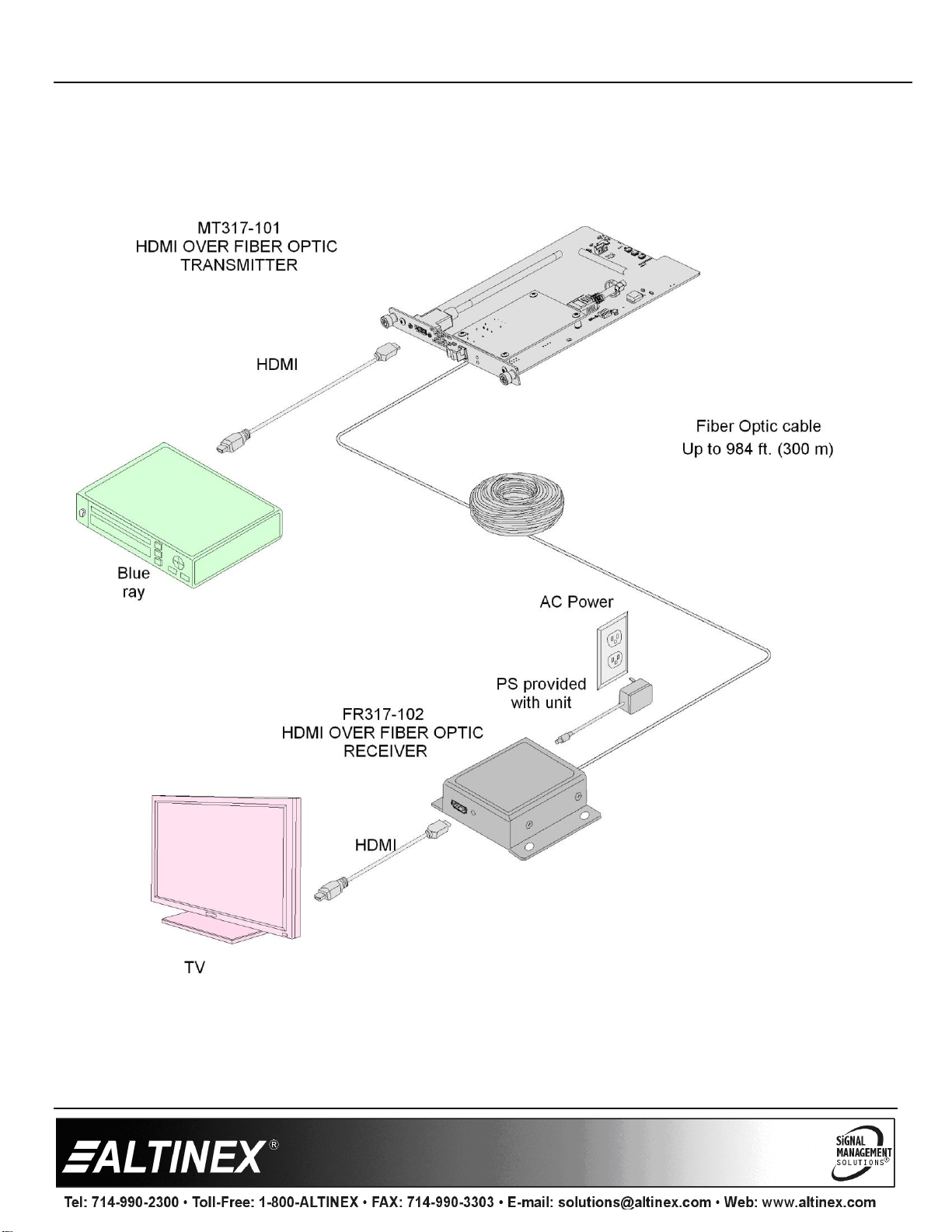
Step 6. Connect an LC UPC to LC UPC Duplex OM3 Multimode cable between the MT317–101 transmitter and a compatible receiver;
MT317-102 or FR317-102.
Step 7. On a LAN, the enclosure IP can be discovered via a UDP broadcast of “?Altinex” to port 30305.
3. Warranty and Return Policies
Please visit the Altinex website at www.altinex.com for details on warranty and return policies. In the case of a unit needing repair,
please complete a RMA (return material authorization) form by clicking the Warranty link located on the bottom of the Altinex
homepage. Once completed, please email the form to s[email protected].
MT317-101User’s Guide
400-0660-001 2
4. Technical Specifications
Specifications are subject to change due to design improvements. Please see www.altinex.com for up to date information.
Features/Description
MT317–101
Input Connectors
HDMI Video
HDMI F, Type A (1)
Output Connectors
Multimode Fiber Out
LC UPC DUPLEX F(1)
Compatibility
Signal types
HDMI
Signal resolution
1080P@60Hz,
1080i, 720P, 576P, 480P,
4Kx2K@30Hz
Receiver
MT317-102
FR317-102
Cable
LC UPC to LC UPC Duplex
OM3 Multimode
Range (Longer range
options are available.)
984 ft (300 m)
Table 1. MT317–101 General
Mechanical
MT317–101
Slots
1
Material
Aluminum
Color
Black
Weight
0.76 lbs. (0.35 kg)
Connector Panel
Black Anodized
T° Operating
10°C-45°C
Humidity
90% non-condensing
MTBF (calc.)
38,000 hrs.
Table 2. MT317–101 Mechanical
Electrical
MT317–101
Video Input Signals
Digital Video + Audio
HDMI Standard
Video Output Signals
Digital Video + Audio
Altinex Standard
Power
+12V
0. 5 A (6 W) max.
Table 3. MT317–101 Electrical
MT317-101User’s Guide
400-0660-001 3
5. About Your MT317–101
•Extend HDMI over Fiber Optic cable
•Multimode transceiver included
•Transmit 4Kx2Kx30 up to 984 ft. (300 m)
•HDCP compliant
•Bandwidth support up to 10.2 Gbps
•Secure video transmission without electromagnet emissions
•Immune to emissions from accompanying/bundled cables
•May be customized to extend range
The MT317–101 is an HDMI extender receiver based on light carrying technology over fiber optic cable. This card allows a standard
HDMI signal to be transmitted up to 984 ft. (300 m) feet over multimode OM3 type cable when paired with a compatible receiver like
the MT317-102 and FR317-102. The transmitter may be an Altinex MultiTasker card inside of another enclosure at a remote location,
or the transmitter can be Altinex’s stand-alone transmitter FR317-101.
The use of fiber optic cable allows for secure transmission of private or classified video. There are no electromagnet emissions to be
picked up or “sniffed” by external monitoring equipment. Fiber optic cable is ideal for hospitals, financial institutions, military, etc.
Like all MultiTasker cards, the MT317–101 can be paired with other MultiTasker cards in the same enclosure for added functionality.
For example, HDMI matrix switcher card, HDMI distribution cards, scalers, etc. Control software can be used to communicate with
the MultiTasker enclosure to monitor the card temperature, power consumption, and event to disable the hardware power in order to
save power when not in use.
MT317-101User’s Guide
400-0660-001 4
6. Application Diagrams
Diagram 1: Typical Setup
MT317-101User’s Guide
400-0660-001 5
Diagram 2: Internal View
MT317-101User’s Guide
400-0660-001 6
7. Operation
7.1 Control
The MT317–101 has many advanced remote-control
capabilities when used in the MultiTasker enclosure. These
capabilities are accessible through standard RS232 or TCP/IP
communication. The actual controlling can be accomplished
through a computer control system or any other device capable
of sending commands.
7.1.1 RS232/TCP Interface
This section lists all the RS232/TCP control and configuration
command formats and their ranges.
The TCP/IP ports have the following default settings:
IP address... 192.168.10.84
Port.............. 23
The rear panel RS232 port has the following settings:
Baud............ 115k
Data bits...... 8
Stop bits...... 1
Parity........... None
Flow............. None
7.1.2 Command Basics
The control commands for the MT317–101 are in a simple
ASCII character format.
1. Square brackets "[ ]" are part of the command.
2. Use uppercase letters for all commands.
3. Spaces are NOT legal characters.
4. Do NOT send carriage returns or line feeds;
these are invalid characters.
A command that instructs the card only to perform an action
will generate feedback of "[Card ID]". The open bracket
followed by the card ID and then a close bracket indicates the
card received and executed a valid command. If the command
requested information from the card, the feedback generated
by the card is the acknowledgement of having received a valid
command.
[C04] Card C4 (slot 4) executed a valid command
Invalid commands generate feedback that includes "ER" and
may also include an error code.
[ERC04] Card C4 (slot 4) failed to execute a command
Check command syntax.
Check values sent are within a valid range.
Commands ending in "S" will be saved into memory.
Commands not ending in "S" are executed, but not restored at
reset or power up.
7.1.3 Conventions Used in this Manual
Card IDs:
In this manual, cards are referenced by their card ID which is
equivalent to their slot number:
C1, C2, C3, C4 ... C20
Group IDs:
Groups are referenced by their group ID:
G1, G2, G3 ... G8
7.2 Description of Commands
Each command consists of three parts: Function, Card ID, and
Save.
[ Function , Card ID Save]
Example: [VERC4]
VER = Function
C4 = Card ID or Group ID
S = Save this setting (optional)
The card ID is a unique identifier, equal to the enclosure slot
number. As the slot number, the value can range from 1 to 20
depending on the enclosure.
The group ID is a number representing a group of cards
defined with the [GROUP] command. When using the group
ID, all cards in the group perform the same instruction.
Changing the position of a card significantly affects the
commands recorded on software definitions or third-party
control systems.
MT317-101User’s Guide
400-0660-001 7
Common Commands
1. [C]
This command displays a user formatted status of the card.
Command Format: [Cii]
Example:
Display the status of the MT317–101 card in slot 4 by
sending [C04].
The MT317–101 returns the status in the format below.
MT317–101
HDMI ON FIBER TX
CARD POWER: 2694 mW
CARD TEMP: 24C
GROUP: NONE
2. [?C]
Read the complete controller configuration in a machine
parseable format.
Command: [?Cii]
Feedback: [(MT317–101C04)(VR690-0429-001C04)
(PR1426C04)(TP23C04)]
All feedback is enclosed in brackets, “[ ]“. Each data field
within the status is enclosed in parentheses. The first two
characters identify the status type. The last three
characters are the card’s ID.
The digits in between represent values and/or settings. All
are fixed lengths using leading zeros for easy parsing.
Following is a breakdown of the above example.
[
Start status
(MT317–101C04)
Model number
(VR690-0429-001C04)
Firmware version
(PR1426C04)
Power in milliwatts
(TP23C04)
Temperature in °C
]
End status
3. [CiS]
This command saves the current card configuration. The
saved configuration is restored after the system is reset or
powered off, then on. This command is common to all
cards, but there are no features to save on the MT317-101.
Command Format: [CiiS]
Cn = Card ID (n = # from 1 to max slots)
S = Save configuration
MT317–101
HDMI ON FIBER TX
CARD POWER: 2694 mW
CARD TEMP: 24C
GROUP: NONE
[SAVEDC4]
4. […S] –SAVE
This command saves the configuration command being
sent in memory. Send [IN3C4S] and after reset or power
up, Input 3 is the active signal. This command only saves
the command sent. Use the [CiiS] command to save all
current settings. This command is common to all cards, but
there are no features to save on the MT317–101.
5. [DISP]
This command returns the card information that is
displayed on the enclosure LCD window.
Command Format: [DISPCii]
Read what is displayed on the LCD by sending [DISPC4].
The feedback displays the text for both the top row and the
bottom row separated by commas.
[MT317–101,HDMI ON FIBER TXC04]
6. [FRST]
This command clears the card, restoring the factory default
settings. This command is common to all cards, but there
are no features to save on the MT317–101.
Command Format: [FRSTCii]
Example:
To clear the card in slot 4, send [FRSTC4]. The card in slot
4 is now returned to its default factory values.
7. [GROUP]
This command assigns a card to a group of cards. If a
group command is sent to the enclosure and the group
number matches, the group command is executed by all
cards in the group.
The is no feedback with group commands and not all cards
or commands support group features.
Command Format: [GROUPxCii]
x = Group ID (x = # from 1 to 8)
Example:
Assign the card in slot 4 to group 2 by sending
[GROUP2C4]. Execute a group command by sending the
command with a group ID. For example, [ON1G4].
8. [HWEN]
This command enables or disables the card hardware,
excluding the main microprocessor. Power to video and
audio circuitry is turned off. Use for saving power but to
keep response time short returning to normal operation.
This is not a group command.
Command Format: [HWENxCii]
x = On/off (1 = on, 0 = off)
Example:
Disable the hardware to the card in slot 4 by sending the
following command:
[HWEN0C4]
MT317-101User’s Guide
400-0660-001 8
9. [MOD]
This command returns the card model number.
Command Format: [MODCii]
Example:
Read the model of the card in slot 4 by sending [MODC4];
feedback is similar to the following:
[MT317–101C04]
10. [PRG]
This command puts the card into firmware update mode.
Only use when working with Altinex Technical Support.
Command Format: [PRGCii]
11. [PWR]
This command returns the card power consumption in
watts.
Command Format: [PWRCii]
Example:
Read the power consumption of the card in slot 4 by
sending [PWRC4]; feedback is similar to the following:
[16.07C04]
12. [PWRM]
This command is the same as the [PWR] command but
returns power milliwatts.
Command Format: [PWRMCii]
Example:
Read the power consumption (in milliwatts) of the card in
slot 4 by sending [PWRMC4]; feedback is like the following:
[16067C04]
13. [SFT]
This command resets the card. It is the equivalent to
powering just the card off and on.
Command Format: [SFTCii]
Example:
Reset the card in slot by sending [SFTC4]. The card
responds with [RSTC04] indicating the card is resetting.
14. [STA]
This command enables and disables automatic feedback
from the card. The feedback format is the same as the [?Ci]
command, but only changes are reported.
Only enable this feature if control software is actively
monitoring changes in the system. Enabling this feature in
an active environment does affect system response times.
Command Format: [STAxCii]
x = On/off (x = 1 to enable, 0 to disable)
Feedback Prefix Definitions:
MT Card Model Number
VR Firmware Revision
PR Power consumption
HW Hardware enable
TP Card Temperature
15. [TEMP]
This command returns the card temperature. The value is
returned in degrees Celsius.
Command Format: [TEMPCii]
Example:
Read the temperature of the card in slot 4 by sending
[TEMPC4]. The card responds with feedback:
[24C04]
16. [VER]
This command displays the software version of the card.
Command Format: [VERCii]
Example:
Send the command [VERC4] to check the version of the
MT317–101 in slot 4. The card returns feedback:
[690-0429-001C04]
690-0429-001= firmware version
C04 = card ID
MT317-101User’s Guide
400-0660-001 9
7.3 Summary of Commands
Common Commands
1. [C] Card status
2. [CiS] Save all settings
3. [?C] Parseable card status
4. […S] Save single command
5. [DISP] Return card information
6. [FRST] Factory reset
7. [GROUP] Set or read group number
8. [HWEN] Hardware enable/disable
9. [MOD] Return card model
10. [PRG] Firmware update mode
11. [PWR] Return card power in watts
12. [PWRM] Return card power in milliwatts
13. [SFT] Reset the card
14. [STA] Enable/disable unsolicited feedback
15. [TEMP] Return card temperature
16. [VER] Return firmware version
MT317-101User’s Guide
400-0660-001 10
8. Troubleshooting Guide
We have carefully tested and have found no problems in the supplied MT317–101. However, we would like to offer suggestions for the
following:
Extender
Symptom
Resolution
LEDs Are OFF
•Make sure the unit is plugged all the way into the MultiTasker slot.
•Make sure the MultiTasker enclosure is connected to AC power and that the power switch on the
front of the unit is turned on.
Check Transmitter
The MT317–101 requires a valid fiber optic signal with HDMI video in order to display video on the
HDMI output. The signal must terminate into a compatible Altinex receiver:
MT317-102, FR317-102.
•Check the receiver; verify power is present.
•Make sure the transmitter LEDs indicate power and status.
No Display
•Check the source (transmitter side) and make sure there is a signal present.
•Make sure the source connected to the transmitter has power and is turned on.
•Run a short fiber cable between the transmitter and receiver. The cable in question may be too long
or of inferior quality. If the image appears, check the cable length and quality. Look for any damage
or creases in the cable.
Poor Output Image
•The source resolution may not be compatible with the projector or other display device. Try other
resolutions from the source.
•The source and display may not be compatible. Connect the source directly to the input of the
projector or other display device. If the image is poor the devices may be incompatible.
•Run a different cable. The cable in question may be too long or of inferior quality.
System Failure
Please call the Altinex Customer Service Department at (714) 990-2300 to have the unit repaired.

Other Altinex Extender manuals

Altinex SIGNAL MANAGEMENT SOLUTIONS TP315-104 User manual

Altinex

Altinex SIGNAL MANAGEMENT SOLUTIONS TP315-104 User manual

Altinex SIGNAL MANAGEMENT SOLUTIONS TP315-103 User manual

Altinex

Altinex SIGNAL MANAGEMENT SOLUTIONS TP315-103 User manual

Popular Extender manuals by other brands

Ihse K487 Series user manual

Ihse

Ihse K487 Series user manual

LevelOne HVE-9111T Quick installation guide

LevelOne

LevelOne HVE-9111T Quick installation guide

DigitaLinx DL-HDE100 owner's manual

DigitaLinx

DigitaLinx DL-HDE100 owner's manual

Artel FiberLink Beamer-V Installation and operation manual

Artel

Artel FiberLink Beamer-V Installation and operation manual

Sinew HD-308T-Tree user manual

Sinew

Sinew HD-308T-Tree user manual

KVM-TEC masterEASY Quick instructions

KVM-TEC

KVM-TEC masterEASY Quick instructions

BBV TXLD installation guide

BBV

BBV TXLD installation guide

ATEN CE790 user manual

ATEN

ATEN CE790 user manual

MuxLab 500460-RX Quick installation guide

MuxLab

MuxLab 500460-RX Quick installation guide

Wheelock SAFEPATH4 SP40/2 Application, Installation, Operation, and Maintenance Manual

Wheelock

Wheelock SAFEPATH4 SP40/2 Application, Installation, Operation, and Maintenance Manual

Rose electronics CRK-2DTPPDVI Specifications

Rose electronics

Rose electronics CRK-2DTPPDVI Specifications

Liberty Digitalinx Series user manual

Liberty

Liberty Digitalinx Series user manual

Tenda A27 Quick installation guide

Tenda

Tenda A27 Quick installation guide

Digitus DS-56200 user manual

Digitus

Digitus DS-56200 user manual

Nikrans NS-GD-Boats-L Product description

Nikrans

Nikrans NS-GD-Boats-L Product description

DARTWOOD Wireless-N WiFi Extender user manual

DARTWOOD

DARTWOOD Wireless-N WiFi Extender user manual

weBoost Office 200 installation guide

weBoost

weBoost Office 200 installation guide

Jaycar AC1732 user manual

Jaycar

Jaycar AC1732 user manual

manuals.online logo
manuals.online logoBrands
  • About & Mission
  • Contact us
  • Privacy Policy
  • Terms and Conditions

Copyright 2025 Manuals.Online. All Rights Reserved.