Alto LINK II User manual

www.altoproaudio.com
!!!!!!!!!!!!!!!!!!!!!!!!!!!!!!!!!!!!!!!!!!!!!!!!!!!!!!!!!!!Version 2.0
MODEL: ALTO LINK II
Revised on Jan.2010

CONTENT
1. Introduction……………………………………………………………….………..…...1
2. Specification………………………………………………………………………...2
3. Block Diagram…………………………….................…….…………….….….....3
4. Schematic Diagram…………………………………...........….….………….…...4
5. Wiring Diagram…………………………………….…...…...…….…………..…...7
6. PCB Layout......................................................................................................8
7. Test Procedure…….......................................................................….……......9
8. Exploded View& Mechanical Parts List……...............................….……....13
9. BOM List……...........................................................………………............…..15

The ▲LTO LINK II is in fact the good solutions for many problems of the large scale sound
reinforcement systems and PA applications. And it can be used as a splitter or a mixer.
For splitter application, just apply the main signal input from the MAIN IN sockets, and
select the SPLITTER mode for each individual channel, then six mono outputs can be
gotten. By depressing the MAIN MIX button, two further outputs can be provided.
For mixer application, select the MIXER mode for individual channel, and feed the input
signal from the mono input, then six input signals can be mixed together, and output from
the MAIN OUT. By depressing the MAIN MIX button, two further inputs can be provided.
Features:
z1 rack size.
zSPLIT/MIX switch for each mono channel.
z2 input,6+2 outputs splitter.
z8 Balance/Pan control for each channel.
zMain input and output level control.
zMAIN LINK function allows to route the MAIN IN signal to MAIN OUT, vice versa.
zLevel meters for each stage.
zXLR balanced connectors for 4 mono channels, and TRS type for another 2 mono
channels.
zDual voltage unit for global operation.
1. Introduction
--- 1 ---

Connectors XLR and 1/4"TRS
Type RF fltered, servo-balanced iuput
Impedance 50 kOhms balanced,25 kOhms unbalanced
Nominal operating level -10 dBu to +4dBu
Max.input level +21 dBubanlanced and unbalanced
CMRR Typ.40dB.>55dB @ 1kHz
Connecters XLR and 1/4"TRS
Type Electronically servo-balanced output stage
Impedance 60 Ohms balanced,30 Ohms unbalanced
Max.input level +22 dBu balanced and unbalanced
Frequenncy response 5 Hz to 200 kHz, +/-3 dB
S/N ratio >95 dBu, unweighted,22Hz to 22kHz
THD 0.002%typ.@+4 dBu, 1kHz. gain 1
Max.input level Variable
Max.output level Variable
Level Variable for each channel
Balance/pan placing in the stereo field
Main Link links the main input signal to the main output
Split/mix changeover from split to mix mode
for each channel
Input level (main) 4-digtal LED display.-120/+12Clip
Output level (main) 4-digtal LED display.-120/+12Clip
Input/output level 4-digtal LED display.-120/+12Clip
USA/Canada 120V∼, 60 Hz
U.K/Australia 240V∼, 50Hz
230V∼, 50Hz
General Export Model
100-120V∼, 200-240V∼,50-60 Hz
Power Consumption max.15 Watts
95-120 V∼:T 315 mAH
210-240V∼:T 200 mAH
Mains Connection Standard IEC receptacle
Dimensions (H*W*D 483(W)×217(D)× 44(H)mm (19"×8.54"×1.7")
Net Weight 3 kg(6.4Ib)
Shipping Weight 3.8kg
Audio inputs
Audio outputs
System
Specifications
Function
Controls
Physical
Function
Switched
Indicators
Europe
Power supply
Fuse
2. Specification
--- 2 ---

3. Block Diagram
--- 3 ---
ALTO LINK II
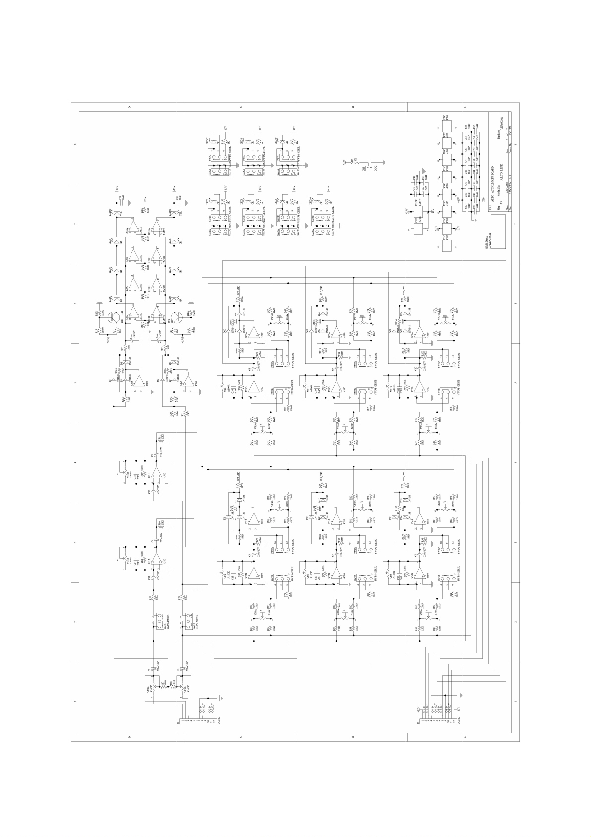
4. Schematic Diagram
--- 4 ---

ALTO LINK II
--- 5 ---
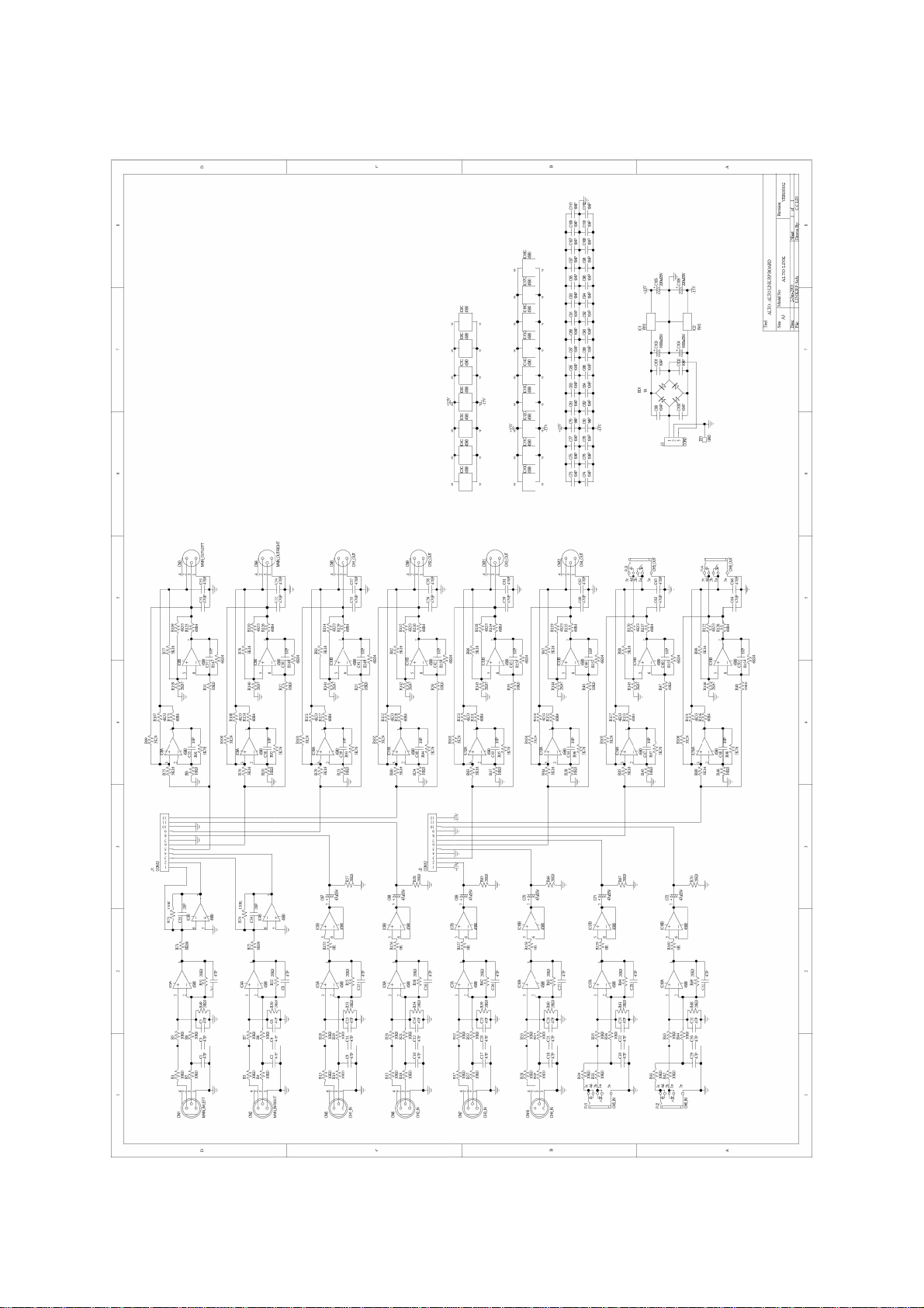
ALTO LINK II
--- 6 ---
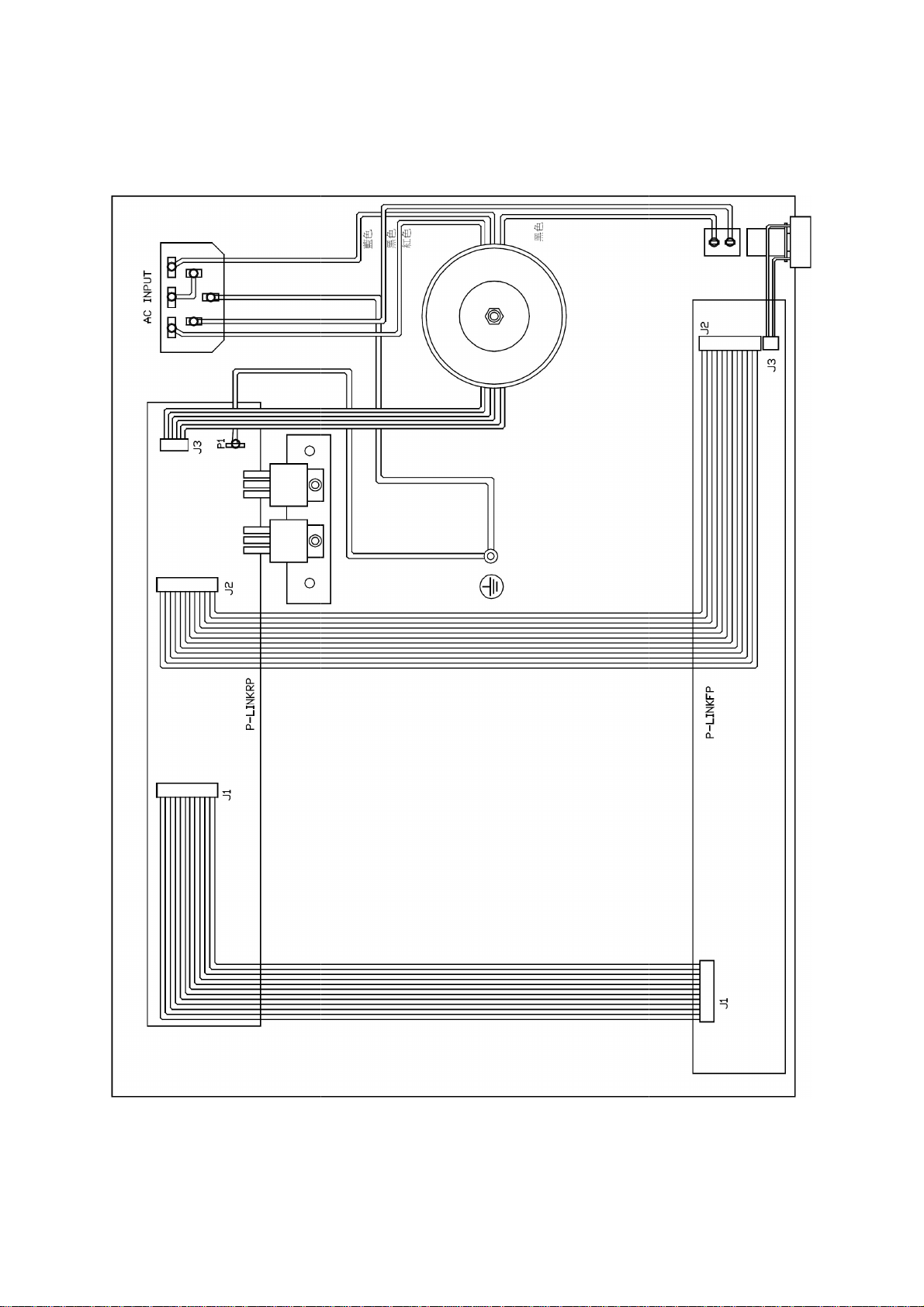
BLACK
RED
BLUE
BLACK
5. Wiring Diagram
--- 7 ---
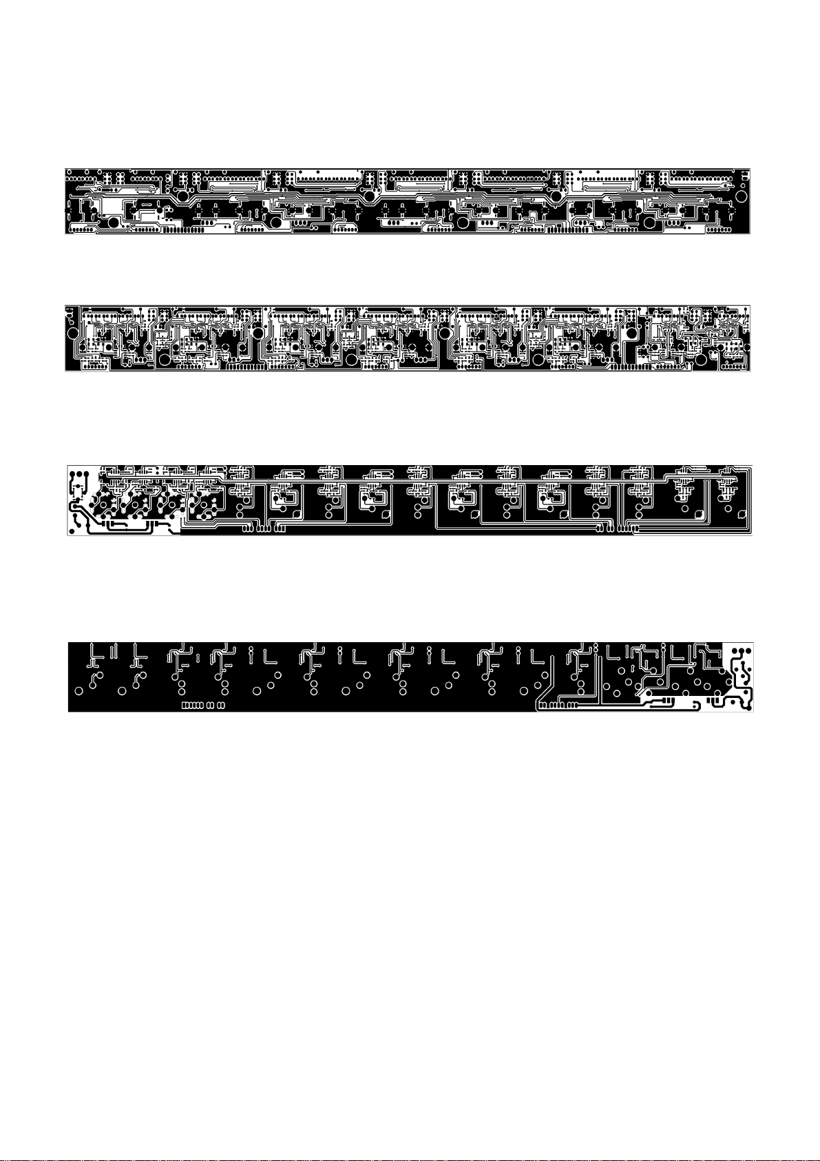
" $ % & ' " #
LINKFP Bottom Layer
LINKRP Top Layer
LINKRP Bottom Layer
6. PCB Layout
--- 8 ---
Table of contents


