ALTOmobile DRIVE 20 User manual

LTO
LTO
TM
DRIVE 20
User's Manual
Version 1.3
---English---

LTO
LTO
TM
Safety Instructions
1
All safety and operating instructions should be read before the equipment is installed and operated.
We recommend that installation be carried out by an authorised mobile electronics installation company.
Please contact your local ALTO Mobile distributor for a list of authorised installers in your country.
To reduce the risk of electric shock and potentially damaging the equipment, do not disassemble the
product. No user serviceable parts inside; refer servicing to qualified personnel.
The equipment should be protected from moisture and rain, especially if mounted in the vehicle's trunk area
or any location that may be susceptible to water ingress.
The equipment should be situated so that its location or position does not interfere with its proper
ventilation. For example, the product should not be situated under carpeting or in a totally sealed
enclosure. Trunk-mounted equipment/amp racks should be well ventilated, using forced air cooling fans if
necessary. The equipment should be situated away from heat sources such as engine exhaust systems and
radiators.
This product is designed for vehicles with a 12 VOLT NEGATIVE GROUND electrical circuit. This product
must not be used in vehicles that use a 24 Volt supply or a positive ground electrical circuit.
Great care must be taken when wiring the product to the vehicle's electrical system. Unless you are fully
familiar and trained in wiring automotive electrical systems, installation should only be undertaken by a
qualified automotive electrician.
TM

LTO
LTO
TM
2
Preface
Dear Customer,
Thank you for choosing the ALTO Mobile DRIVE20 2-way digital crossover/speaker management system.
We hope you'll love the results you get from your new digital sound processor and enjoy using it as much as
we enjoyed developing it.
The DRIVE20 is the result of considerable development work in our R&D centres in Europe and the Far East
and is a close cousin of ALTO's professional audio products. We've been designing products for musicians
and recording studios for many years - the product you now have in your hands has a fine pedigree.
The core of our digital audio products is a sophisticated DSP (Digital Signal Processor) coupled with state-of-
the-art algorithms developed by our software team over the last 7 years.
The car audio environment is worlds away from the controlled listening area of the recording studio, and yet
much of the sound processing so important to recording engineers can be applied with spectacular success
to the automotive environment. ALTO Mobile is a specialist division of audio and computer software
engineers, but above all we're car audio enthusiasts. We love the challenge of trying to reproduce studio
quality sound inside a moving vehicle.
TM
TM
Channel Layout
Analog Input section
Analog Output section
2 inputs 4 outputs 1 subwoofer output
Inputs: 2 RCA - F
Input Impedance: 400 kOhms
Max. input Level: 18 dBV
Outputs: 5RCA-F
Output Impedance: 600 Ohms
Max. output level: 10 dBV

Digital / Analog Interface
Remote Control
Power Supply
Amplitude Response:
Signal to Noise Ratio
THD N
Conversion
Conversion
-RS 232 for PC Connection (user interface on PC screen with MS 9X-OS)
Type:
Voltage supply:
LTO
LTO
TM
Preface
20 Hz - 20KHz 0.2 / 1.5 dB
90 dB
0.005 % @ 1KHz 3 dB
input 20 bits Sigma - Delta
output 24 bits Sigma - Delta
Servo - controlled, Switching
11Vdc - 15Vdc
3

LTO
LTO
TM
Preface
4
5 PEQ
5 PEQ
Delay
Delay
Gain
Gain
R
O
U
T
I
N
G
Volume Out 1
5 PEQ Band
Pass Polarity
Compressor
Delay Mute
Volume Out 2
5 PEQ Band
Pass Polarity
Compressor
Delay Mute
Volume Out 3
5 PEQ Band
Pass Polarity
Compressor
Delay Mute
Volume Out 4
5 PEQ Band
Pass Polarity
Compressor
Delay Mute
Input Left
Input Right
We're convinced you are an important member of our team and we listen to what you say and take on board
your suggestions. It's this feedback that helps us create the products you want. Thank you.
ALTO MOBILE TEAM
Block Diagram: DRIVE20
TM

LTO
LTO
TM
5
Introduction
please read this manual first
In purchasing the DRIVE20 you have a very powerful digital sound processor. You'll be eager to play with it -
we know what it's like when you get a new toy - but . If you have had your
DRIVE professionally installed and setup for you, there should be no need to touch the controls again.
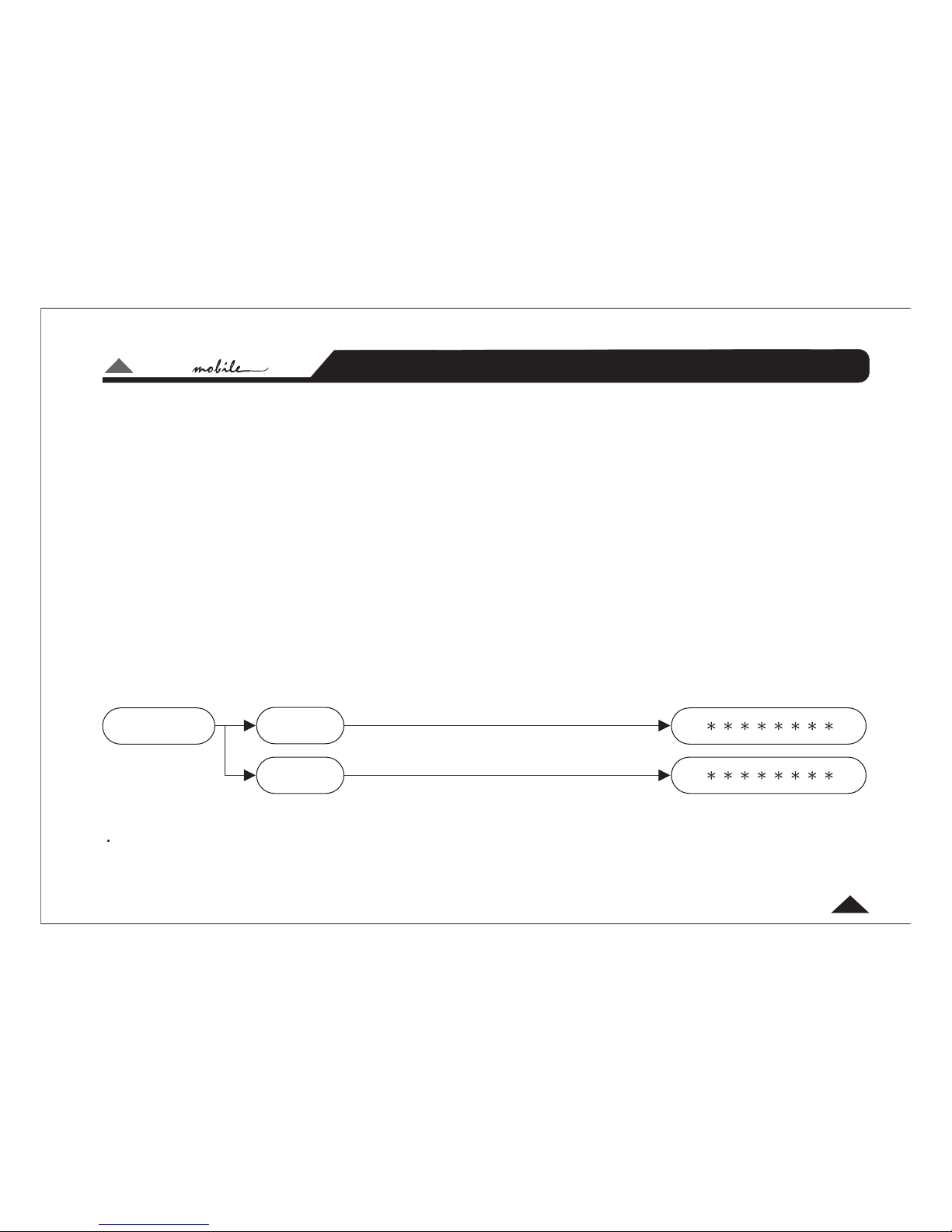
DRIVE20 uses a password access system to safeguard against unauthorised parameter adjustment.
We recommend you leave the controls exactly as set by your installer. It is extremely
important that you take great care not to send frequencies to speakers that have not been designed to handle
them. In particular, midrange speakers and tweeters must be protected from low frequencies. It would be all
too easy to damage speakers while 'playing' with the settings of the DRIVE20.
If you have not had the product installed in your vehicle yet, that's obviously the first thing you'll need to do.
We strongly recommend that you have the unit professionally installed by a specialist company authorised by
the ALTO Mobile distributor in your country. The installation instructions in this manual are for guidance only
and are not intended to be a thorough explanation of all the steps involved in correctly fitting this unit. The
instructions assume that the person installing the equipment has been trained to carry out such work.
A computer interface and Windows software is available for professional setup of the system. The same
level of control is available via the front panel buttons and LCD display but interfacing to a computer makes
things easier.
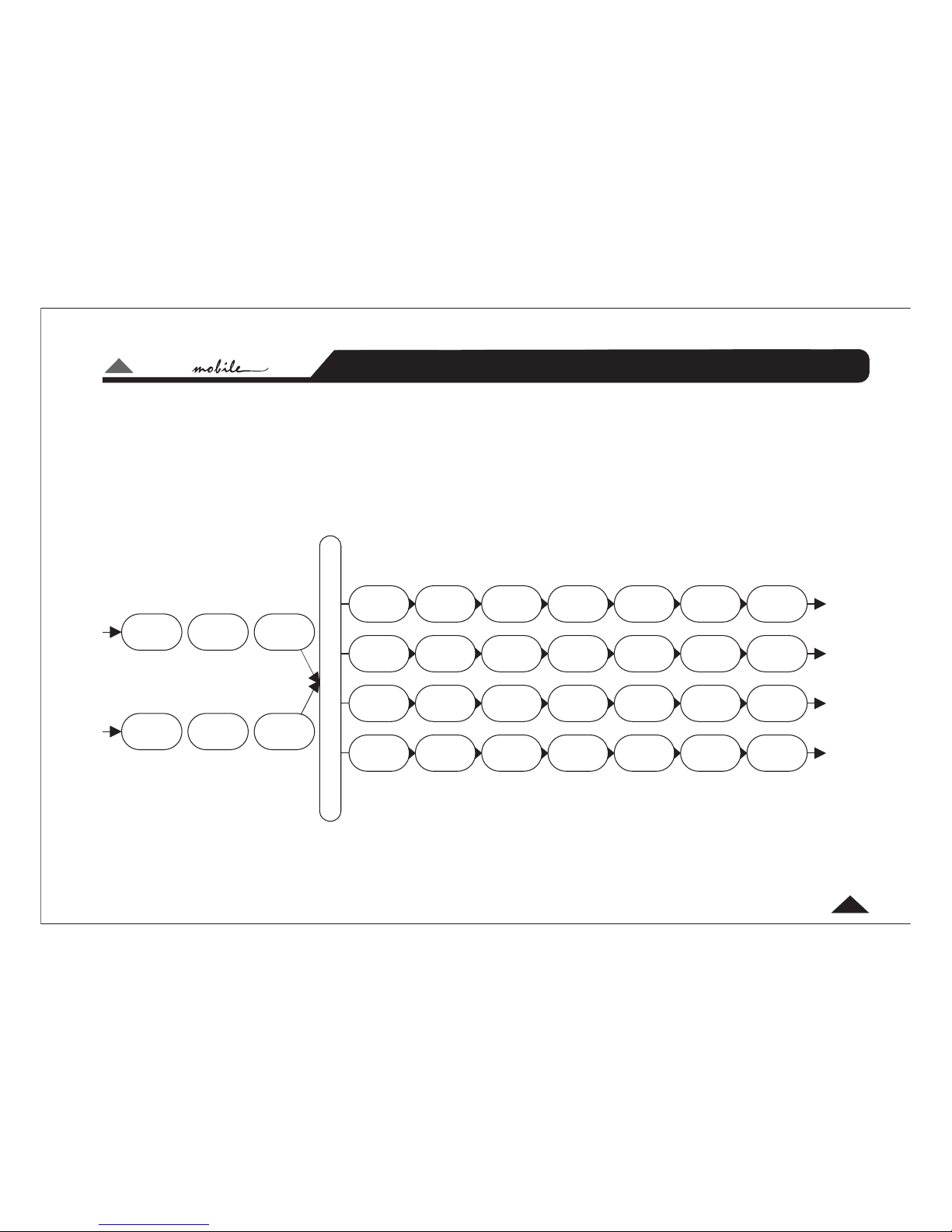
The DRIVE20 is a very sophisticated digital crossover, but actually it can do far more than any conventional
activecrossover,whichiswhywerefertoitasa .Thereareavarietyofuser-
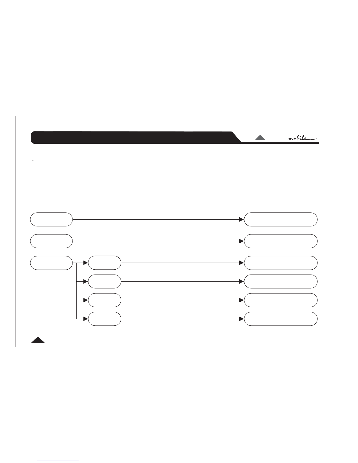
adjustable parameters explained in this manual. Once you've worked on setting the sound the way you like it,
you can store it in one of the 64 available user preset memory locations. These can be quickly recalled from
the panel buttons.
Important Warning
Speaker Management System
TM
TM

LTO
LTO
TM
1 2
1. Use these controls to match the pre-amp output level from your car audio source unit.
DRIVE20 MAX Input level: 8 VRMS (18 dBV)
2 These two controls adjust the level of the signal sent to the separate
terminal, and also adjust the Low-Pass filter point.
Input Gain Controls:
Subwoofer Gain/Frequency:
SUBWOOFER OUTPUT
.
3
6
User Interface

LTO
LTO
TM
User Interface
77
3. Each frequency band has a pair of Output Gain controls. Use these controls to
match the optimum pre-amp input level of your amplifier.
DRIVE20MAXOutputlevel(DSP@0dB):3VRMS(9.6dBV)
Generally speaking you should set DRIVE20's output level controls at about 8/10 and your amplifier's gain
control at its lowest possible sensitivity setting, taking care not to run the sound into distortion. For example,
if the gain controls of your amplifier are marked from 150mV to 4V, set them initially to 4V and work down to
increase the volume. If the sound is distorted, keep the amp gains at low setting (in this example, at 4V) and
reduce the Output Gain Controls on the DRIVE20.
Use these to select the required Parameter Group and the specific parameter that you wish to
adjust. The group or individual parameter is shown in the LCD display. DRIVE20 uses a multi-level menu
system. You move down through the menu - from parameter group to each specific parameter you want to
adjust - by using the Key. Only after pressing are changes made.
While searching using the keys, the currently selected settings remain unchanged.
Choose a Parameter Group using the keys. Now press the key. This action moves you one
level lower in the menu system. Use the keys again to choose a specific parameter to adjust.
Press again. Now make your changes using the keys. When you are happy with your
changes, press once more. The new settings will now be applied and should be audible.
Use this key to move back up the menu system without making any changes to the current
settings.
Output Gain Controls:
Up/Down Keys:
ENTER ENTER
Enter Key: UP/DOWN
UP/DOWN ENTER
UP/DOWN
ENTER UP/DOWN
ENTER
Escape (ESC) Key:

LTO
LTO
TM
8
Setting the various parameters of the DRIVE20 is achieved in one of two ways. A standard computer serial
interface allows connection to a computer and setup using a dedicated software package. Alternatively the
unit can be configured via a multi-level menu system using DRIVE20's panel buttons and the LCD display.
This manual only covers setup and adjustment using the panel buttons.
Of all the ALTO Mobile sound processors, DRIVE20 (and sister model DRIVE30) is potentially the one most
likely to cause damage to your speakers if it is not setup correctly. You must take great care when setting the
crossover points for the mid and high bands. In order to safeguard settings, a password system has been
incorporated to block access to unauthorised users.
After power-up, the display will show vu-meter level data for the two input channels, the currently active
preset and the LOCK or UNLOCK condition. Pressing takes you to the main menu (i.e. take you down
one level). Pressing backtracks to the previous screen (i.e. goes up one level).
If the unit is in the UNLOCK mode, you will be able to access all menu options. If the unit is in the LOCK mode,
only the menu will be available.
Setup Introduction
ENTER
ESC
Password setup
TM
Parameter Menus & Setup
Password Setup Real
Password
New
Password
Password Setup
Real Password ENTER UP/DOWN Real
Password ENTER Password Real Password
is a combination of 6 digits selected with the and buttons (
> > ). The currently selected digit blinks. Where the input is the
same as the stored or default password, the system will be placed in the UNLOCK condition. Otherwise it

LTO
LTO
TM
Parameter Menus & Setup
9
will be in the LOCK State.
is the function used to change the default value of in order to create a
custom password. The initial default value is 000000. The selection of the follows a similar
procedure as with the ( > > ). To update the ,
the system must be in the UNLOCK Condition.
New Password Real Password
New Password
Real Password New Password ENTER change New Password
We recommend that you set a memorable custom password and write it down, but keep it at home ( your
installer may have set a new password and over-written the factory default). To place the unit in LOCK mode,
simply enter an incorrect password ( > >
note:
Real Password ENTER Password).
Load Setup Preset 0, 1, ..., 64
Store Setup Preset 1, ..., 64 (user)
Name editing
Muting Setup Output 1
Output 2
Off/On
Off/On
Output 3
Output 4
Off/On
Off/On

LTO
LTO
TM
Parameter Menus & Setup
10
Preset Load
Preset Store
Muting Setup
65 presets are available, one factory preset and 64 user-definable presets. Preset 0 is the default factory
preset used as a start point when configuring the system. Attempting to load an empty user preset will
produce a warning message on the display.
Allows configurations to be stored as a user preset. Once a configuration has been stored, its preset location
can be renamed. The name is a combination of 8 characters of your choice selected with the and
buttons. The currently selected digit blinks.
Any of the four outputs can be muted (zero output). An output channel must first be selected and then the
MUTE status is selected using buttons to toggle between ON and OFF conditions.
Note: It is also possible to mute any of the outputs and store this data within individual presets by setting
channel outputs to OFF in the menu. This can be useful for isolating faults.
ENTER
UP/DOWN
the UP/DOWN
Routing setup
Routing Setup Output 1
Output 2
Off/InL, InR, InL R
Output 3
Output 4
Off/InL, InR, InL R
Off/InL, InR, InL R
Off/InL, InR, InL R

LTO
LTO
TM
Parameter Menus & Setup
11
Input L/R Setup Gain
Equalizer
Setup Gain
PEQ 1 / 15dB step 0.5dB
/ 12dB step 0.5dB
Frequency
Band Width
20Hz-20KHz step 1/2oct
0.05-3oct step 0.05oct
Frequency
Band Width
20Hz-20KHz step 1/2oct
0.05-3oct step 0.05oct
Gain
PEQ 2 / 15dB step 0.5dB

LTO
LTO
TM
Parameter Menus & Setup
12
Equalizer
Setup
Frequency
Band Width
20Hz-20KHz step 1/2oct
0.05-3oct step 0.05oct
Gain
PEQ 3 / 15dB step 0.5dB
Frequency
Band Width
20Hz-20KHz step 1/2oct
0.05-3oct step 0.05oct
Gain
PEQ 5 / 15dB step 0.5dB
Frequency
Band Width
20Hz-20KHz step 1/2oct
0.05-3oct step 0.05oct
Gain
PEQ 4 / 15dB step 0.5dB

LTO
LTO
TM
Parameter Menus & Setup
13
Delay 0-99msstep1ms
0 - 978 us step 21us
Delay Fine
Delay Adj
Routing Setup
Input Channel Setup (INPUT L, INPUT R)
Gain:
Equalizer setup:
Allows setting of the crossover channel routing configuration. For each of the 4 Output Channels you can
choose to send just the Left Input signal, the Right Input signal, a combination of both Left and Right Input
signals (usually for feeding subwoofers) or no input (OFF). The latter effectively mutes that channel. First
select an output channel. Now, using the buttons to scroll through the list, choose from the routing
options. To confirm your choice press . To cancel your choice press .
The following parameter adjustments are available for each input channel.
Input Gain
5-band parametric equalization
Delay
A multi-layer menu system is used. The various layers and the choices within the deepest layer are selected
using the and keys. Use the (Escape) key to cancel a selection and backtrack up
through the menu layers.
Effectively acts as a master balance control.
From here you can select each of the 5 parametric filters. For each filter you can adjust
UP/DOWN
ENTER ESC
UP/DOWN ENTER ESC

LTO
LTO
TM
Parameter Menus & Setup
14
Gain (cut/boost), Frequency (the centre frequency of the filter), and Band Width (the extent to which
frequencies around the centre frequency will also be adjusted).
This allows a delay to be set on each channel. May be useful in certain circumstances. Also, setting a
delay on one side while leaving the other with no delay can produce a very interesting effect of added width
and spatial depth. This is not to be confused with 'time alignment' (see under Output Channel Setup).
Delay:
Output Setup
(1/2/3/4) Volume
Equalizer
Setup Gain
PEQ 1 / 15dB step 0.5dB
/ 12dB step 0.5dB
Frequency
Band Width
20Hz-20KHz step 1/12oct
0.05-3oct step 0.05oct
Frequency
Band Width
20Hz-20KHz step 1/12oct
0.05-3oct step 0.05oct
Gain
PEQ 2 / 15dB step 0.5dB

LTO
LTO
TM
Parameter Menus & Setup
15
Equalizer
Setup
Frequency
Band Width
20Hz-20KHz step 1/12oct
0.05-3oct step 0.05oct
Gain
PEQ 4 / 15dB step 0.5dB
Frequency
Band Width
20Hz-20KHz step 1/12oct
0.05-3oct step 0.05oct
Gain
PEQ 3 / 15dB step 0.5dB
Frequency
Band Width
20Hz-20KHz step 1/12oct
0.05-3oct step 0.05oct
Gain
PEQ 5 / 15dB step 0.5dB

LTO
LTO
TM
Parameter Menus & Setup
16
Band Pass
Setup High Pass
Order
Frequency 20Hz-20KHz step 1/12oct
Bypass,1234ord
Polarity Direct/Invers
Order Bypass,1234ord
Low Pass 20Hz-20KHz step 1/12oct
Frequency
Output Setup
(1/2/3/4)
Compressor Threshold 29dB/0dB step 1dB
Release 0.4, 0.5, 0.7, 1.4 sec
Attack 0.05, 0.1, 0.2, 0.3 sec

LTO
LTO
TM
Parameter Menus & Setup
17
Output Channel Setup (OUTPUT 1~4)
Volume:
Although the Output channels are labelled in pairs as High and Low band, each channel is capable of
being set to operate anywhere in the audible frequency spectrum. The labels are purely for convenience. The
following parameter adjustments are available on each output channel.
Output Volume Level
5-band parametric equalization
Band-Pass Filter (low-pass + high-pass)
Polarity (phase)
Dynamic processor
Delay (time alignment)
A multi-layer menu system is used. The various layers and the choices within the deepest layer are selected
using the and keys. Use to cancel a selection and backtrack up through the menu
layers.
Acts as a master system gain control. Can be used as a safety feature to limit the maximum output
available when adjusting the panel-mounted gain controls.
UP/DOWN ENTER ESC
Delay 0-99msstep1ms
0 - 978 us step 21us
Delay Fine
Delay Adj

LTO
LTO
TM
Parameter Menus & Setup
18
From here you can select each of the 5 parametric filters. For each filter you can adjust
Gain (cut/boost), Frequency (the centre frequency of the filter), and Band Width (the extent to which
frequencies around the centre frequency will also be adjusted).
Here is where you setup the crossover point and slope for each of the output channels.
Use the keys to select the Low-Pass or High-Pass filter. Now choose the Frequency or Filter Order
(slope) and make the desired settings.
With the High-Pass filter, the level of frequencies BELOW the crossover point will be reduced at the rate
dictated by the slope setting. 1 Order (6dB), 2 Order (12dB), 3 Order (18dB) or 4 Order (24dB) per
octave.
With the Low-Pass filter, the level of frequencies ABOVE the crossover point will be reduced at the rate
dictated by the slope setting (as above).
Either filter can be switched out by setting the Filter Order (slope) to BYPASS.
The polarity or 'phase' of each channel can be switched Direct/Inverse.
This is a form of dynamic processing used extensively in recording studios. It provides a
way of controlling the dynamic range by limiting the higher musical peaks to give a more consistent output
level. In the car the benefits include the ability to have the volume level high enough to hear softer passages
above road and engine noise without having to frantically grab the volume control on loud peaks.
sets the point below full output (0db) where the compressor/limiter begins to operate. and
determine the time it takes for the compressor/limiter to react to changes in signal level. Generally
you can leave and at their default settings.
Also known as 'Time Alignment'. This allows a small amount of delay to be set on each of the
channels 1-4. The amount of delay is usually calculated from physical measurements of the distances
between the various speakers and the driver's ears. The delay compensates for the difference in speaker
mounting positions. When applied correctly to all speakers in the system, the result is an improvement in the
Equalizer setup:
Band Pass setup:
Polarity 0/180 :
Compressor setup:
Delay setup:
UP/DOWN
Threshold Attack
Release
Attack Release
st nd rd th

LTO
LTO
TM
Parameter Menus & Setup
19
apparent stage position, height, depth and the location and focus of the performers on the imaginary stage
(usually across the dashboard).
More information is available via our web site.
Table of contents
Popular Recording Equipment manuals by other brands

Vicon
Vicon Valerus-PoE NVR quick start guide

OPTOGATE
OPTOGATE PB-06 user manual

Aeta Audio Systems
Aeta Audio Systems SCOOP STUDIO user manual

Trilithic
Trilithic Visionary HD/SD Overlay System Hardware installation and configuration manual

Fiberplex
Fiberplex FOI-6010 user manual

Cochlear
Cochlear Baha 6 Max user manual