Altrex MHB 60 User manual

Instruction manual – NL x EN x FR
760170-A-0221
MHB 60
MHB 80
1. NL Nederlands
2. EN English
3. FR Français
NEN-EN1808: 2015
Machinery Directive (2006/42/EG)

2www.altrex.com
NL
1. Inleiding
Deze handleiding is uitsluitend van toepassing op Altrex MHB tijdelijke hangbrug systeem, hierna te noemen ‘hangbrug’, zoals
omschreven in deze handleiding opbouw en gebruik, hierna te noemen handleiding. Voor u met de opbouw van de hangbrug
begint, dient u deze handleiding zorgvuldig door te lezen. De gewenste hangbrug dient conform deze handleiding te worden
opgebouwd en gebruikt. Alle aanwijzingen in deze handleiding dienen strikt te worden opgevolgd. Indien de aanwijzingen uit
deze handleiding niet worden opgevolgd, zal dat gemakkelijk kunnen leiden tot ernstige ongevallen. Altrex kan niet aanspra-
kelijk worden gesteld voor schade als gevolg van het niet conform de handleiding opbouwen en gebruiken van een Altrex
hangbrug systeem. De werkgever, toezichthouder en gebruiker zijn verantwoordelijk voor de juiste toepassing van de hang-
brug volgens deze handleiding en zij dienen er voor te zorgen dat deze handleiding te allen tijden bij de werkzaamheden met
de hangbrug op de werkplek aanwezig is. Extra exemplaren van de handleiding kunnen bij uw Altrex dealer worden besteld.
Lokale wet- en regelgeving kan aanvullende maatregelen bevatten op deze handleiding.
Altrex BV - Mindenstraat 7 - 8028 PK Zwolle - Tel.: +31(0)38 455 77 00 - Email: [email protected] - www.altrex.com
Inhoud
1. Inleiding
2 Type hangbrugsysteem
3. Denities
4. Veiligheidsrichtlijnen ter voorkoming van ongevallen
5. Onderdelen en afmetingen hangbrug
6. Controleer vóór gebruik
7. Opbouw / montage hangbrug
8. Dakophangpunten
9. Bediening van de hangbrug
10. Verplaatsen van de hangbrug
11. Beëindiging van het gebruik en afbouw
12. Inspectie, zorg en onderhoud
13. Garantiebepalingen
14. Controlelijst hangbrug systeem
Bijlagen
T1: Overzicht onderdelen MHB60 en MHB80
T2: Conguratietabellen MHB60
T3: Conguratietabellen MHB80
T4: Belastingstabellen MHB60 en MHB80
T5: Conguratietabel dakbalken ADB600 en ADB800
T6: Belastbaarheidstabel dakbalken
2. Type hangbrugsysteem
Normen
- EN1808
- Machinerichtlijn 2006/42/EG
- CE
Type hangbruggen
- MHB60 - met eindbeugels (2 - 15 m)
- MHB60 - met doorloopbeugels (2 - 21m)
- MHB80 - met eindbeugels (2 - 18 m)
- MHB80 - met doorloopbeugels (2 - 26m)
Gebruiksomstandigheden
- Maximale belasting: zie belastingstabel
- Max. windbelasting: 12,7 m/s (max. 6 Beaufort)
- Temperatuur bereik: -20°C tot +55°C
- Relatieve luchtvochtigheid: 30% - 95%
- Energiebron: een aardlekschakelaar van 30 mA en een automatische zekering van voldoende ampères (type C) moeten
worden gebruikt (zie ook handleiding takel)
Toepassing
- De installatie omvat het werkplatform, ophangbeugels, de elektromechanische takels inclusief besturing en
veiligheidsinrichtingen en dakbalken.
- De installatie wordt als tijdelijk werkplek toegepast in bouw, inspectie, en onderhoud van gevels, schoorstenen, torens etc.
- De installatie mag niet worden gebruikt in silo’s, tenzij een aantal maatregelen is getroen. Neem contact op met uw
leverancier voor details hierover.
- De installatie is niet bedoeld voor het gebruik als lift voor personen of goederen.
3. Denities
- Hangbrug: het werkplatform als onderdeel van een tijdelijke hangbrug systeem.
- Tijdelijke hangbrug systeem: hangbrug systeem bestaande uit een werkplatform, takels, centrale bedieningskast,
staalkabels en dakophangpunt, dat kan worden opgebouwd uit losse componenten, voor het tijdelijk verschaen van
toegang tot een gebouwgevel.
- Takel: elektrisch apparaat dat langs een staalkabel kan klimmen of dalen, terwijl het een last draagt, zoals bijvoorbeeld een
werkplatform
- Centrale bedieningskast (CCB): bedieningspaneel waarmee de takels worden aangestuurd.
- Dakophangpunt: een constructie op dakniveau, bedoeld voor de ophanging van een werkplatform.
- Dakbalk: speciek type dakophangpunt, voornamelijk bestaand uit losneembare hoofdbalken (voor, midden en achter
sectie), verrijdbare voor- en achterbok, een schokdemper, contragewichten. De dakbalk wordt gemonteerd met
verbindingspennen met borgclip.

3
www.altrex.com
NL
- Ophangkabel: staalkabel, bevestigt aan het dakophangpunt, langs welke de takel klimt of daalt.
- Ophangbeugel: constructie die een geschikte verbinding mogelijk maakt tussen een werkplatform en een speciek type
takel.
- Eindophangbeugel: ophangbeugel die zich aan een uiteinde van het werkplatform bevindt en tevens dienst doet als
eindleuning.
- Doorloopbeugel: ophangbeugel die zich op een bepaalde afstand van een uiteinde van het werkplatform bevindt, waarmee
een overstek van het werkplatform wordt gecreëerd.
- Work Load Limit:(= WLL): nominale capaciteit van een takel. De belastbaarheid van een werkplatform is onder andere
gebaseerd op de WLL van een takel, net als de capaciteit en het vereiste aantal contragewichten van een dakbalk.
- Conguratie-en belastbaarheidstabellen: lijst met toegestane platformlengten die, in combinatie met takelcapaciteit en
type ophangbeugel, een bepaalde maximale belastbaarheid genereren.
- Bevestigingspen met borgclip: onderdeel voor de verbinding van de losse componenten van het hangbrug systeem.
4. Veiligheidsrichtlijnen ter voorkoming van ongevallen
Ernstig letsel of de dood kan het gevolg zijn van onjuiste opbouw of verkeerd gebruik van het tijdelijke
hangbrug systeem.
!
Elke tijdelijk hangbrug systeem mag uitsluitend worden opgebouwd en gebruikt zoals omschreven in
deze handleiding en conform de conguratie- en belastbaarheidstabellen.
Gebruik het tijdelijk hangbrug systeem niet tenzij u de handleiding volledig heeft gelezen en begrepen, en
is voldaan aan alle eisen en voorwaarden in deze handleiding.
Het tijdelijk hangbrug systeem mag alleen worden opgebouwd, afgebroken en veranderd onder leiding
van een bevoegd persoon en door werknemers die voor de beoogde werkzaamheden een toereikende
opleiding hebben ontvangen.
!
!
!
- Houd er rekening mee dat de hangbrug slechts een onderdeel is van een tijdelijk hangbrug systeem. Er moet voldaan
worden aan de instructies van iedere fabrikant. Daarnaast moet er voldaan worden aan lokale wet- en regelgeving.
- Houd deze handleiding altijd bij de hangbrug.
- Dit document is alleen van toepassing op Altrex MHB hangbruggen.
- Gebruik alleen de nieuwste versie van de ociële Altrex handleiding. De nieuwste versie kan opgevraagd worden bij uw
Altrex dealer.
- Extra kopieën van labels, stickers en tekstplaten, zijn verkrijgbaar indien de originelen beschadigd, onleesbaar of kwijt
mochten raken. Benader hiervoor uw leverancier.
- Controleer vóór gebruik alle onderdelen op beschadigingen, vervormingen of andere afwijkingen. Controleer of alle
onderdelen aanwezig zijn conform de conguratietabel in deze handleiding.
- Het opbouwen en gebruiken van de hangbrug is niet toegestaan tenzij alle onderdelen aanwezig zijn en gebruikt worden.
- Stop onmiddellijk het gebruik van de hangbrug indien één van de onderdelen van het complete hangbrug systeem niet goed
functioneert of is beschadigd. Gebreken in de hangbrug, takels, veiligheidsinrichtingen of staalkabels moeten onmiddellijk
aan de verantwoordelijke persoon worden gerapporteerd.
- Gebruik alleen originele Altrex MHB hangbrug onderdelen. Het mixen met onderdelen van andere fabrikanten is NIET
toegestaan.
- Breng op geen enkele wijze veranderingen aan in de hangbrug componenten! De hangbrug is ontworpen, berekend,
geproduceerd en getest volgens vaste standaards.
- Zorg dat de verbindingspennen gemonteerd worden volgens de opbouwinstructie. Zorg dat elke verbindingspen is geborgd
met de borgclip.
- Gebruik de hangbrug niet als deze heeft blootgestaan aan extreme hitte, door bijvoorbeeld brand. Haal deze hangbrug uit
het gebruik. De sterkte eigenschappen kunnen zijn aangetast.
- Gebruik geen zuren, basen of andere corrosieve substanties die de sterkte van aluminium kunnen beïnvloeden. Verwijder
alle hangbrug onderdelen die ervan worden verdacht blootgesteld geweest te zijn aan de genoemde substanties.
- GEVAAR – metaal geleidt elektriciteit. Gebruik nooit een metalen platform in de buurt van hoogspanningslijnen. Benader de
lokale elektriciteitsmaatschappij voor aanbevelingen.
- Gebruik de installatie zoals in deze handleiding omschreven niet in silo’s, schachten of ondergrondse toegang. Speciale
voorzorgsmaatregelen moeten worden getroen voor deze specieke toepassingen.
- Overbelast de hangbrug niet en bouw geen grotere conguraties dan aangegeven in de conguratie- en
belastbaarheidstabellen. Laat geen zware voorwerpen op de hangbrug vallen.
- Toegang en verlaten van de hangbrug mag alleen op de grond plaatsvinden
- De hangbruginstallatie moet minimaal door 2 personen worden bemand.
- In geval van nood moet men altijd iemand op de grond kunnen bereiken. Bijvoorbeeld met een mobile telefoon.
- Zorg dat gereedschap gezekerd is tegen vallen.
- Voorkom struikelgevaar: houd de hangbrug horizontaal, zorg dat de werkvloer vrij is van obstakels, vuil, olie, vet en dergelijke.
- Wees er van bewust deze veiligheidsvoorschriften niet alles omvattend zijn. Gedegen training is verplicht voor de opbouw en
het gebruik van deze hangbrug.

4www.altrex.com
NL
5. Onderdelen en afmetingen hangbrug
- Zie bijlage T1 voor een gedetailleerd overzicht van de onderdelen en hun massa.
- Zie bijlage T2 en T3 voor de conguratietabellen.
A. Langsdrager
B. Vloer
C. Dwarsdrager
D. Eindophangbeugel
E. Eindleuning
F. Leuningstaander
G. Leuning
H. Wiel
I. Muurafhouder
J. Verbindingspen
K. Doorloopbeugel
A.
B.
C.
D.
F.
G.
H.
I. J.
E.
K.
A.
B.
C.
F.
H. I.
J.
6. Controleer vóór gebruik
- Gebruik het tijdelijk hangbrug systeem niet tenzij u de handleiding volledig heeft gelezen en begrepen, en is voldaan aan
alle eisen en voorwaarden in deze handleiding.
- Gebruik handschoenen, werkschoenen en een helm ter voorkoming van verwondingen tijdens het opbouwen, gebruik en
afbreken.
- Controleer vóór gebruik alle onderdelen op beschadigingen, vervormingen of andere afwijkingen (zoals bijvoorbeeld
gescheurde las door overbelasting). Controleer of alle onderdelen aanwezig zijn conform de conguratietabel in deze
handleiding.
- Controleer of de hele hangbruginstallatie veilig is en in perfect werkende staat.
- Controleer de hangbruginstallatie ten alle tijde op stabiliteit tegen kiepen.
- Controleer of er geen obstructies langs de baan van het werkplatform zijn.
- Zorg dat er een plek beschikbaar is waar personen veilig in en uit kunnen stappen.
- Zorg dat het gebied rond en onder het werkplatform afgesloten is of veilig voor passanten. (Bijvoorbeeld door hekwerk,
overdekte passages, etc.)
- Controleer alle verbindingen, takels, staalkabels (o.a. kabeldiameter), dakbalken en het totale contragewicht.
- Controleer of de ophangbeugels uitgelijnd zijn met de (dak)ophangpunten.
- Controleer de installatie volgens de controlelijst, zie hoofdstuk 14
- Bovengenoemde controles moeten door een deskundig persoon worden uitgevoerd na de opbouw, vóór ieder gebruik
(dagelijks) en na elke noodstop of incident.
- Controleer aan de hand van de belastbaarheidstabellen in bijlage T4 of de maximaal toelaatbare belasting niet wordt
overschreden en controleer het maximaal aantal personen die op de werkbrug aanwezig mogen zijn. Deze tabellen staan
ook op de eindophangbeugel of doorloopbeugel van de hangbrug.
- Controleer of het dakophangpunt geschikt is voor de takelcapaciteit van de gebruikte takels en controleer de belastbaarheid
van de dakconstructie.
- Controleer of het juiste aantal contragewichten is gebruikt voor de opgebouwde dakbalkconguratie. Zie ook de
conguratie- en belastbaarheidstabellen in bijlage T5 en T6.
MHB 60
MHB 80

5
www.altrex.com
NL
7. Opbouw / montage hangbrug
Lees vóór de opbouw van de hangbrug de conguratietabellen in bijlagen T2 en T3 en de belastbaarheidstabellen in bijlage T4.
Bouw alleen hangbruggen die zijn toegestaan volgens deze handleiding.
7.1 Opbouw hangbrug met eindbeugels
1. Plaats de langsdragers in de dwarsdragers en borg deze met de verbindingspennen (4 pennen per langsdrager).
2. Borg de verbindingspennen met de rode borgclips.
3. Herhaal deze stappen tot de gewenste bruglengte is bereikt.
4. Monteer de wielen en borg deze met verbindingspennen.
5. Monteer de leuningstaanders en borg deze met verbindingspennen. Zorg ervoor dat de bovenzijde van de leuningstaanders
zich minimaal 1 meter boven de vloer bevinden.
6. Monteer de eindophangbeugels en borg deze met verbindingspennen (4 st per eindophangbeugel). Zorg ervoor dat de
tekstplaat op de eindophangbeugel aan de binnenzijde van de brug leesbaar is.
7. Controleer of alle verbindingspennen geborgd zijn met de rode borgclips.
8. Plaats de vloeren tussen de langsdragers. Klik ze achter de verende borgpallen. Plaats alleen vloeren van dezelfde lengte
als de langsdrager.
9. Monteer de leuningen in de leuningstaanders en borg deze met verbindingspennen. Borg de verbindingspennen met de
rode borgclips.
10. Monteer de muurafhouders. Zorg ervoor dat het onderste deel onder de langsdrager haakt, het bovenste deel over de
kantplank geplaatst wordt en de 2 schroeven stevig (hand vast) zijn aangedraaid.
11. Monteer de takels op de eindophangbeugels en de centrale bedieningskast op de hangbrug volgens de handleiding van de
takel:
- Handleiding Takel Bisomac 210 600 kg (752942)
- Handleiding Takel Bisomac 210 800 kg (752943)
- Handleiding Takel Astro (760110)
- Handleiding Takel Titan (760111)
12. Monteer een kabelgewicht aan alle staalkabels, 20 cm boven de grond.

6www.altrex.com
NL
4. Monteer de wielen en borg deze met verbindingspennen.
5. Monteer de leuningstaanders en borg deze met verbindingspennen. Zorg ervoor dat de bovenzijde van de leuningstaanders
zich 1 meter boven de vloer bevinden.
6. Monteer de eindleuningen en borg deze met verbindingspennen (4 st per eindleuning). Let op! De verbindingspennen
moeten van binnen naar buiten geplaatst worden. Anders kan de rode borgclip niet geplaatst worden. Zie detail afbeelding.
7. Controleer of alle verbindingspennen geborgd zijn met de rode borgclips.
8. Plaats de vloeren tussen de langsdragers. Klik ze achter de verende borgpallen. Plaats alleen vloeren van dezelfde lengte
als de langsdrager.
9. Monteer de leuningen aan één zijde van de hangbrug (gebouwzijde) in de leuningstaanders en borg deze met
verbindingspennen. Borg de verbindingspennen met de rode borgclips.
10. Monteer de muurafhouders. Zorg ervoor dat het onderste deel onder de langsdrager haakt, het bovenste deel over de
kantplank geplaatst wordt en de 2 schroeven stevig (hand vast) zijn aangedraaid.
11. Lees hoofdstuk 7.3: Montage doorloopbeugel
12. Bepaal de positie waar de doorloopbeugels op de hangbrug worden gemonteerd:
- Bekijk op de tekstplaat op de doorloopbeugel of de tabel in bijlage T4 wat de kabelafstand mag zijn.
- Let op dat de ophangbeugels uitgelijnd zijn met de (dak)ophangpunten.
- Zorg ervoor dat de hangbrug in balans is: de overstek/overhangende deel moet aan beide zijde van de brug
gelijk zijn.
7.2 Opbouw hangbrug met doorloopbeugels
1. Plaats de langsdragers in de dwarsdragers en borg deze met de verbindingspennen (4 pennen per langsdrager).
2. Borg de verbindingspennen met de rode borgclips.
3. Herhaal deze stappen tot de gewenste bruglengte is bereikt.

7
www.altrex.com
NL
13. Plaats de doorloopbeugels aan de zijde van de brug waar nog geen leuningen zijn geplaatst.
- Schuif de doorloopbeugel onder de hangbrug
- Til de doorloopbeugel op en haak de knieregelsteun over de langsdrager (doorloopbeugel
is licht gekanteld)
- Controleer of de knieregelsteun van doorloopbeugel goed achter de langsdrager haakt.
- Kantel de doorloopbeugel rechtop, bevestig de kantplankhaak over de kantplank van de
langsdrager en draai de bout van de kantplankhaak stevig aan.
14. Plaats de leuningen in de leuningstaanders en borg deze met verbindingspennen.
Borg de verbindingspennen met de rode borgclips.
15. Monteer de takels op de doorloopbeugels en de centrale bedieningskast op de hangbrug volgens de handleiding van
de takel:
- Handleiding Takel Bisomac 210, 600 kg (752942)
- Handleiding Takel Bisomac 210, 800 kg (752943)
- Handleiding Takel Astro (760110)
- Handleiding Takel Titan (760111)
16. Zorg na de montage van de takel ervoor dat de hijs- en de veiligheidskabel door de geleiderollen worden geleid. De
kabeluitvoer van de takel bepalen of de linker of de rechter geleiderollen worden gebruikt.
17. Monteer een kabelgewicht aan alle staalkabels, 20 cm boven de grond.
7.3. Montage doorloopbeugel
1. Zorg ervoor dat de onderbalk in zijn horizontale positie komt. Plaats de
verbindingspen en borg deze met de rode borgclip.
2. Monteer de kop van de doorloopbeugel.
- Let op: controleer of de kop geschikt is voor de takel die
gebruikt gaat worden
- Plaats één verbindingspen (kort) en borg deze met de rode
borgclip
- Plaats één lange verbindingspen, inclusief de twee
geleiderollen, en borg deze met twee rode borgclips
3. Controleer of de knieregelsteun op de juiste hoogte gemonteerd is.
- Onderste 2 gaten voor MHB60
- Bovenste 2 gaten voor MHB80

8www.altrex.com
NL
8. Dakophangpunten
- Altrex dakbalken:
- ADB 600 LAAG (WLL 600 kg)
- ADB 600 HOOG (WLL 600 kg)
- ADB 800 LAAG (WLL 800 kg)
- ADB 800 HOOG (WLL 800 kg)
- Dakbalken zijn ontworpen en geclassiceerd voor een bepaalde Work
Load Limit (WLL). Deze WLL geeft aan wat de
maximale capaciteit van de gebruikte takel mag zijn.
- De Altrex dakbalken mogen uitsluitend gebruikt worden op platte daken.
- Controleer de belastbaarheid van de dakconstructie waar de dakbalk geplaatst wordt, voordat de installatie wordt
opgebouwd. Tijdens normaal gebruik, kan de voorbok van de dakbalk een belasting van 1150kg krijgen en de
achterbok van 700kg.
- Om de belasting door het dak te laten dragen kan het nodig zijn om onderlegplaten te gebruiken voor een verdeling
van de belasting.
- Onder extreme omstandigheden zijn deze waarden nog hoger, de belasting op de voorbok kan oplopen tot 3.000kg
- Let op: Het dak moet in staat zijn om de belasting te weerstaan die bij een eventuele extreme omstandigheid zou
kunnen optreden (zoals bij kabelbreuk)!
8.1 Voorbereiding
Bestudeer de conguratie- en belastbaarheidstabellen in bijlagen T5 en T6
- Bepaal welke type dakbalk gebruikt gaat worden.
- Bepaal de lengte van de oversteek: ‘outreach B’
- ADB 600 LAAG / ADB 600 HOOG
- Standaard : 0,9m of 1,2m.
- Met verlengde buitenbalk (415095): 1,6m, 1,9m of 2,2m
- ADB 800 LAAG / ADB 800 HOOG: 0,9m of 1,2m
- Bepaal de afstand tussen de voor- en achterbok: ‘supportdistance A’ die
gewenst is: 4,5m, 5,0m of 5,5m.
- Kijk op de tekstplaat (bijlage T6) bij de takelcapaciteit ‘takel’ die gebruikt
gaat worden. Op de kruising van supportdistance A en de takelcapaciteit
wordt het vereiste aantal contragewichten gevonden (20kg)
- Voorbeeld: Een DAKBALK 400 - 600 HOOG wordt geïnstalleerd,
met een oversteek (‘outreach B’) van 1,2m en een afstand tussen de bokken (‘supportdistance A’) van 5,0m. De
takel heeft een WLL van 600kg. In de belastbaarheidstabel (bijlage T6) kan worden afgelezen dat er 20
contragewichten van 20 kg nodig zijn.
- Bepaal de benodigde lengte van de staalkabels en elektrakabels. Gebruik alleen kabels die voldoen aan de
specicaties van de takelfabrikant. Reken voor de staalkabels minimaal 10 meter extra dan de hoogte van het gebouw.
8.2 Veilig werken op daken
- Indien het dak waarop de dakbalk moet worden geplaatst voldoende veiligheid biedt door middel van een borstwering
of een permanente leuning van minimaal 1m hoogte, hoeft er geen valbeveiliging te worden gebruikt.
- Als er binnen een afstand van 4m vanaf de rand moet worden gewerkt, op een dak dat geen veiligheid biedt door
middel van een borstwering of leuning van voldoende hoogte, geldt het volgende:
- Er mag uitsluitend op het dak gewerkt worden indien men is aangelijnd aan een verankeringspunt op het dak
die geschikt is voor persoonlijke valbeveiliging. Dit geldt tijdens montage, verplaatsen en demontage van de
dakophangconstructie.
- Indien het dak een borstwering van ten minste 10cm hoogte heeft, mag een compleet gemonteerde dakbalk,
waarbij de contragewichten zijn geplaatst en de wielen in de geremde positie staan, worden gebruikt als
verankeringspunt voor persoonlijke valbeveiliging. Men kan daarvoor de verbindingspen achterop de
schokbrekerarm gebruiken. Dit geldt voor bijvoorbeeld het doorvoeren van de ophang- en veiligheidskabel in de
dakbalk die al in positie staat.
- In alle andere gevallen moet een andere manier van valbeveiliging aangebracht worden, b.v. door middel van
randbeveiliging of een verplaatsbaar verankeringspunt.
- Dakbalken mogen alleen worden ge(de)monteerd of verplaatst bij goede weersomstandigheden en bij maximaal
windkracht 6 Beaufort.
- Dakbalken mogen niet worden ge(de)monteerd of verplaatst bij onweer, sneeuw, hagel of ijsafzetting.
8.3 Opbouw/montage dakbalk
Bestudeer de conguratie- en belastbaarheidstabellen in bijlagen T5 en T6. Controleer of alle onderdelen aanwezig zijn.
Let op: de voorbok en de achterbok moeten altijd op dezelfde hoogte staan (zelfde horizontale vlak).
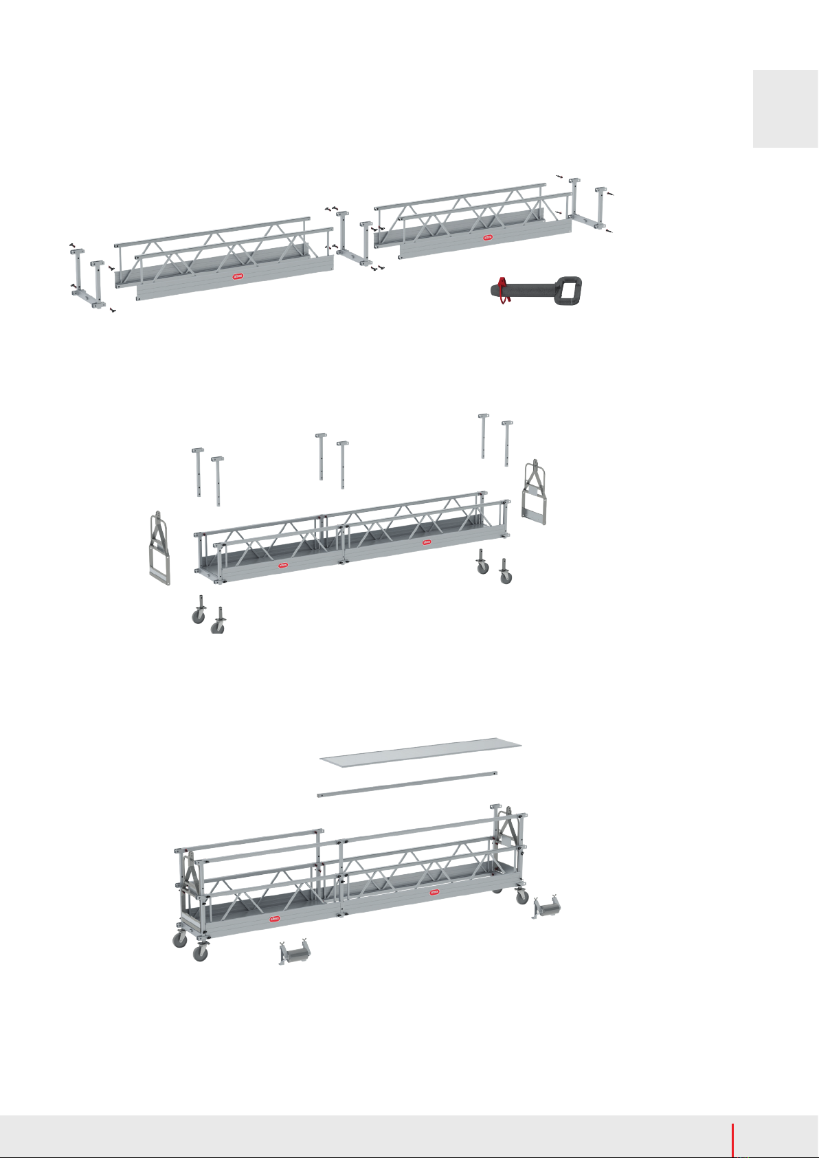
8.3.1 ADB 600 (LAAG en HOOG)
1. Monteer de buitenbalk, binnenbalk en buitenbalk in elkaar tot de gewenste lengte (‘supportdistance A: 4,5m, 5,0m of
5,5m). Borg de balken met verbindingspennen en borg deze met de rode borgclip.
2. Schuif de buitenbalk in de voorbok, totdat het 1e borggat van de balk in lijn ligt met het borggat van de voorbok (2e
borggat bij gebruik van de verlengde buitenbalk 415095)
3. Schuif de voorbalk in de buitenbalk tot de gewenste oversteek (Outreach B). Borg de voorbalk, voorbok en buitenbalk
met de verbindingspen. Borg deze verbindingspen met de rode borgclip.
4. Schuif de buitenbalk in de achterbok, totdat het 1e borggat van de balk in lijn ligt met het borggat van de achterbok.
5. Schuif de schokbrekeradapter in de buitenbalk. Borg de schokbrekeradapter, achterbok en buitenbalk met een
verbindingspen. Borg de verbindingspen met de rode borgclip.

9
www.altrex.com
NL
6. Monteer de schokbrekerarm aan de schokbreker adapter. Monteer hieraan weer de contragewichthouder. Beide worden
gemonteerd met een verbindingspen. Borg ze met de rode borgclip.
7. Alleen bij ADB600 HOOG: monteer 2x een diagonaalschoor tussen de buitenbalk en de bok (voorbok+achterbok). Gebruik
hiervoor 2 verbindingspennen per diagonaalschoor. Borg ze met de rode borgclip.
8. Klik de geborgde haken van de hijskabel en de veiligheidskabel aan de schokbrekerarm. Voer de uiteinden van de kabels
enkele meters door de kop van de voorbalk. Let op dat de kabels over de kabelschijven lopen, de kabels overal vrij
hangen en niet met elkaar in de knoop kunnen komen.
9. Breng de dakbalken in de juiste positie en zet de wielen op de rem. Zorg er voor dat de wielen op rijplaten of rijgoten staan
voor het verdelen de belasting op het dak en het kunnen verrijden van de dakbalken.
10. Breng de contragewichten aan op de contragewichthouder en borg ze met de stalen pen + hangslot om wegnemen door
derden te voorkomen. Voor het juiste aantal gewichten: zie belastbaarheidstabel in bijlage T6.
11. Laat de kabels langzaam zakken tot op het grondniveau waar de hangbrug zich bevindt.
12. Monteer de hoogste stand plaat op de staalkabels volgens de voorschriften van de takelfabrikant.
13. Nadat gecontroleerd en vastgesteld is dat alles volgens de voorschriften gemonteerd is, is de dakbalk klaar voor gebruik.
8.3.2 ADB 800 (LAAG en HOOG)
1. Monteer de buitenbalk, binnenbalk en buitenbalk in elkaar tot de gewenste lengte (‘supportdistance A: 4,5m, 5,0m of 5,5m).
Borg de balken met verbindingspennen en borg deze met de rode borgclip.
2. Monteer de galg op de voorbok met behulp van 2 verbindingspennen. Borg de pennen met de rode borgclip.
3. Alleen bij ADB 800 HOOG:
- Monteer 2x de verlenging voorbok in de voorbok met een verbindingspen. Borg de pennen met de rode borgclip.
- Monteer 2x de diagonaalschoor tussen de voorbok en de bokverbreding met behulp van 2 verbindingspennen.
Borg de pennen met de rode borgclip.
4. Schuif de buitenbalk in de voorbok, totdat het 1e borggat van de balk in lijn ligt met het borggat van de voorbok. Borg de
voorbalk en de voorbok met een verbindingspen. Borg deze verbindingspen met de rode borgclip.
5. Schuif de voorbalk in de galg tot de gewenste oversteek (Outreach B). Borg de voorbalk en galg met de verbindingspen.
Borg deze verbindingspen met de rode borgclip.
6. Schuif de buitenbalk in de achterbok, totdat het 1e borggat van de balk in lijn ligt met het borggat van de achterbok.
7. Schuif de schokbrekeradapter in de buitenbalk. Borg de schokbrekeradapter, achterbok en buitenbalk met een
verbindingspen. Borg de verbindingspen met de rode borgclip.
8. Monteer de schokbrekerarm aan de schokbreker adapter. Monteer hieraan weer de contragewichthouder. Beide worden
gemonteerd met een verbindingspen. Borg ze met de rode borgclip.
9. Alleen bij ADB800 HOOG: monteer 2x een diagonaalschoor tussen de buitenbalk en de bok (voorbok+achterbok). Gebruik
hiervoor 2 verbindingspennen per diagonaalschoor. Borg ze met de rode borgclip.
10. Monteer de kettingspanner compleet aan de galg en aan de schokbrekeradapter met behulp van 2 verbindingspennen en
borg deze. Breng de ketting nu op spanning door middel van de schakels van de ketting en de borgpen.
11. Klik de geborgde haken van de hijskabel en de veiligheidskabel aan de schokbrekerarm. Voer de uiteinden van de kabels
door het stalen deel van de kettingspanner op de galg en vervolgens enkele meters door de kop van de voorbalk. Let op
dat de kabels over de kabelschijven lopen, de kabels overal vrij hangen en niet met elkaar in de knoop kunnen komen.
12. Breng de dakbalken in de juiste positie en zet de wielen op de rem. Zorg er voor dat de wielen op rijplaten of rijgoten staan
voor het verdelen de belasting op het dak en het kunnen verrijden van de dakbalken.
13. Breng de contragewichten aan op de contragewichthouder en borg ze met de stalen pen + hangslot om wegnemen door
derden te voorkomen. Voor het juiste aantal gewichten: zie belastbaarheidstabel in bijlage T6.
14. Laat de kabels langzaam zakken tot op het grondniveau waar de hangbrug zich bevindt.
15. Monteer de hoogste stand plaat op de staalkabels volgens de voorschriften van de takelfabrikant.
16. Nadat alle onderdelen en de conguratie is gecontroleerd en vastgesteld is dat alles volgens de voorschriften gemonteerd
is, is de dakbalk klaar voor gebruik.
8.4 Verplaatsen dakbalk
1. Voordat de dakbalk verplaatst wordt, moet gecontroleerd worden of staalkabels onbelast zijn (hangbrug staat op de grond)
en de kabels voldoende speling hebben. Haal bij voorkeur de staalkabels uit de takels.
2. Zorg ervoor dat de voedingskabel wordt losgekoppeld van de elektriciteitsbron.
3. Controleer of het dakconstructie waarover de dakbalk verplaatst wordt, sterk genoeg is. Plaats bij voorkeur rijplaten of
rijgoten.
4. Indien nodig kunnen de contragewichten tijdelijk worden verwijderd.
5. Verplaats de dakbalken naar de gewenste positie en controleer of de afstand tussen de dakbalken gelijk is aan de afstand
tussen de takels.
6. Zet de wielen op de rem.
7. Plaats en borg de contragewichten indien die zijn verwijderd en herstel de stroomvoorziening.
8. Controleer of de takels zicht recht boven de dakbalken bevinden
9. Controleer of het tijdelijke hangbrug systeem nog steeds voldoen aan alle voorschriften.
8.5 Beëindiging en demontage
- Na het beëindigen van de werkzaamheden moeten eerst de staalkabels gedemonteerd worden, voordat contragewichten
of andere onderdelen van de hangbruginstallatie gedemonteerd mogen worden.
- De dakbalk wordt gedemonteerd in de omgekeerde volgorde van de montage

10 www.altrex.com
NL
9. Bediening van de hangbrug
- De takels worden bediend met de centrale bedieningskast op het werkplatform.
- Gebruik alleen de centrale bedieningskast en elektriciteitskabels die door de takelfabrikant worden geleverd of
voorgeschreven.
- De energie toevoerkabel moet zijn voorzien van een trekontlasting. Deze vastmaken aan de langsdrager.
- De takels kunnen met de centrale bedieningskast op de volgende manieren worden bediend:
OMHOOG / OMLAAG schakelaar Takels stijgen / dalen tegelijk
LINKS / RECHTS keuzeschakelaar In de stand LINKS of RECHTS, wordt slecht één van beide takels bediend wanneer
de OMHOOG / OMLAAG knop wordt ingedrukt. Een mogelijke scheefstand van het
platform kan op deze manier worden gecorrigeerd.
NOODSTOP knop In geval van nood kan de hoofdtoevoer van energie worden onderbroken
- Het elektrisch schema is weergegeven aan de binnenzijde van het deurtje van de centrale bedieningskast.
- Het werkplatform mag alleen verticaal stijgen of dalen. Het werkplatform moet in een horizontale positie gehouden
worden tijdens het stijgen, dalen en gebruikspositie. Lees de handleiding van de takel voor meer informatie over de
bediening van de takels.
- Voor het gebruik van handgereedschap is een contactdoos beschikbaar die van de centrale bedieningskast komt.
Alleen geaard of dubbel geïsoleerd gereedschap mag worden gebruikt.
- Wees ervan bewust dat deze richtlijnen niet allesomvattend zijn. Goede training voor alle personen die dit materiaal
opbouwen, heropbouwen, afbreken of gebruiken is noodzakelijk.
- Ondanks dat het niet verplicht is, kan voor de eigen veiligheid gekozen worden om een aanlijnbeveiliging toe te passen.
Deze aanlijnbeveiliging kan worden bevestigd aan de openingen in de eindophangbeugel. De doorloopbeugels zijn
standaard niet voorzien van voorzieningen ten behoeve van aanlijnen. In het geval dat doorloopbeugels worden
toegepast kan ervoor worden gekozen om de eindleuningen te vervangen door eindophangbeugels. Indien dit niet
gewenst is, kan gebruik worden gemaakt van een valbeveiligingssysteem vanaf het dak.
- De installatie mag alleen opgebouwd, afgebroken en veranderd worden onder leiding van een bevoegd persoon en
door werknemers die voor de beoogde werkzaamheden een toereikende opleiding hebben ontvangen.
- Het werkplatform is bedoeld om horizontaal te hangen. Grensschakelaars worden geactiveerd bij een eventuele helling
van meer dan 14° in langsrichting.
- Raadpleeg de handleiding van de takels wanneer deze niet goed functioneren.
10. Verplaatsen van de hangbrug
- Laat het werkplatform op de grond zakken.
- Haal de staalkabels uit de takels.
- Verplaats het werkplatform naar de gewenste positie.
- Verplaats de dakbalken naar de overeenkomstige nieuwe positie. Zie hoofdstuk 8.4 voor het verplaatsen van dakbalken.
- Controleer de volgende punten:
- Controleer of de dakbalken zich op de juiste locatie bevinden
- Controleer of de afstand tussen de kabels gelijk is aan de afstand tussen de ophangbeugels.
- Controleer of de dakbalken op de juiste manier zijn geïnstalleerd
- Controleer of de dakbalken op de rem staan
- Controleer of de hoogste stand afslagplaten correct op de staalkabels zijn gemonteerd
- Indien aan bovengenoemde punten is voldaan, kunnen de staalkabels ingevoerd worden in de takels en kunnen de
ballastgewichten weer op de kabels bevestigd worden (ongeveer 20 cm van de grond)
- Controleer of er nog steeds voldaan wordt aan alle punten in de controlelijst hangbrug systeem (hoofdstuk 14).
11. Beëindiging van het gebruik en afbouw
- De hangbrug installatie moet buiten gebruik worden gesteld:
- Indien niet / niet meer wordt voldaan aan de eisen en gebruiksomstandigheden uit deze handleiding.
- De installatie tijdelijk of langdurig niet wordt gebruikt.
- Aan het einde van de werkdag.
- Buiten gebruik stellen van de hangbrug installatie:
- Laat het werkplatform op de grond zakken.
- Verwijder de energietoevoerkabel van de energietoevoerbron.
- Zorg dat de hangbruginstallatie niet toegankelijk is voor onbevoegden.
- Afbouw: de hangbrug dient in omgekeerde volgorde te worden gedemonteerd, in vergelijking tot de opbouwmethode.
12. Inspectie, zorg en onderhoud
- Hangbrug onderdelen dienen met zorg te worden gehanteerd en vervoerd, zodat beschadiging wordt voorkomen.
- Opslag dient zodanig te zijn georganiseerd dat uitsluitend onbeschadigde delen in de juiste aantallen beschikbaar komen
voor de opbouw van de hangbrug.
- Controleer alle beweegbare delen op vervuiling en een goede werking.
- Controleer alle onderdelen op beschadiging. Beschadigde, versleten of verkeerde onderdelen mogen niet worden
gebruikt. Vervang deze uitsluitend door originele Altrex onderdelen. Deze moeten op dezelfde wijze gemonteerd worden
als het te vervangen onderdeel, om ongevallen te voorkomen. Montage (bevestiging) en/of reparatie geschiedt voor eigen
rekening en risico. Altrex is niet aansprakelijk voor schades veroorzaakt door foutieve montage en/of reparatie.
- Hangbruggen moeten periodiek worden gekeurd door een deskundige.
13. Garantiebepalingen
Ga voor de Altrex garantiebepalingen naar www.altrex.com/warranty

11
www.altrex.com
NL
14. Controlelijst hangbrug systeem
OPBOUWER: Punt 1 t/m 34 horen elke eerste opbouw te worden gedaan en bij wijzigingen. en te worden ondertekend door
een voor de opbouw bevoegd persoon.
GEBRUIKER: Punt 7 t/m 34 horen te worden uitgevoerd voor elk gebruik van de installatie en afgetekend door de gebruiker.
NR. Controle die moet worden uitgevoerd JA NEE N.V.T.
1 Is de opbouw van de dakophanging (dakbalk) uitgevoerd volgens de opbouwvoorschriften?
2 Is de opbouw van het werkplatform uitgevoegd volgens de opbouwvoorschriften?
3 Is de afstand tussen de (eventuele) doorloopbeugels volgens de opbouwvoorschriften?
4 Is een eventueel overstek van het werkplatform niet groter dan toegestaan volgens de fabrikant?
5 Zijn de takels juist gemonteerd?
6 Is het aantoonbaar dat de gehele installatie is geïnspecteerd?
7 Is de afstand tussen de dakbalken en de ophangbeugels gelijk (evenwijdige ophangkabels)?
8 Is de afstand tussen gevel en dakophangpunten voldoende?
9 Is het juiste aantal contragewichten aangebracht en gezekerd met een slot?
10 Zijn er maatregelen getroen ter voorkoming van een te hoge belastingconcentratie?
11 Zijn alle wielen van de dakbalk op de rem gezet?
12 Zijn eventuele dakhaken op de juiste manier opgebouwd?
13 Zijn eventuele achterwaartse beveiligingen op de juiste manier aangebracht?
14 Bevinden zich deze achterwaartse beveiligingen direct achter de dakhaken?
15 Is de elektrische energievoorziening geaard?
16 Is de gebruikte zekering op zijn minst 16 Ampère?
17 Hebben de gebruikte elektriciteitskabels de juiste doorsnede?
18 Is(zijn) de trekontlasting(en) voor de elektriciteitskabel(s) op de juiste manier aangebracht?
19 Zijn alle elektriciteitskabels vrij van beschadigingen?
20 Zijn de staalkabels vrij van beschadigingen?
21 Zijn de bovenste stand afslagplaten minimaal 10 cm onder de ophangpunten bevestigd?
22 Zijn de ballastgewichten aan de staalkabels gemonteerd op 20 cm boven de grond?
23 Werken alle functies van de centrale bedieningskast?
24 Blijft de belasting beneden de maximaal toegestane belasting volgens de tekstplaat?
25 Werken de hoogste stand schakelaars op de takels?
26 Is de noodafdaalfunctie getest op goed functioneren?
27 Is het noodafdaal wiel aanwezig op de takel? (NB: geldt niet voor Bisomac takels)
28 Werkt de valbeveiliging?
29 Zijn de vereiste certicaten aanwezig of onmiddellijk opvraagbaar?
30 Is de gebruikshandleiding aanwezig?
31 Zijn er voorzorgsmaatregelen getroen ter bescherming van omstanders?
32 Blijft de windkracht op de werklocatie beneden de windkracht 6Beaufort (13,8 m/s)?
33 Werken de overlast beveiliging / schuinstand beveiliging / slappe kabel beveiliging?
34 Is de bevestiging van de takel aan de doorloop- of eindbeugel corrosie vrij?
Opgebouwd door:
Datum:
Naam:
Functie:
Handtekening:
Bij bemerkte tekortkomingen wordt “Nee” aangekruist, zodat deze kunnen worden verholpen.
Uiteindelijk hoort de controlelijst afgetekend te worden.
N.B: De MHB moet niet worden gebruikt zolang deze tekortkomingen niet verholpen zijn.
Gecontroleerd en vrijgegeven door:
Datum:
Naam:
Functie:
Handtekening:

12 www.altrex.com
EN
1. Introduction
This manual applies exclusively to Altrex MHB temporary suspended platforms (hereinafter: ‘suspended platforms’) as descri-
bed in this safety, assembly & user manual (hereinafter: ‘manual’). Prior to starting to assemble the suspended platform, you
should carefully read this manual. The required suspended platform should be assembled and used in accordance with this
manual. All instructions in this manual must be followed strictly. Failure to follow the instructions contained in this manual can
easily result in serious accidents. Altrex cannot be held liable for any loss resulting from the assembly or use of an Altrex sus-
pended platform that is not in compliance with the manual. The employer, supervisor and user are responsible for the correct
use of the suspended platform in accordance with this manual and they must ensure that this manual is available at all times
when work is being carried out using the suspended platform. Additional copies of the manual can be ordered from your Altrex
dealer.
Local legislation and regulations may encompass additional measures to those stated in this manual.
Altrex BV – Mindenstraat 7 – 8028PK Zwolle – Tel.: +31 (0)38 455 7700 – Email: [email protected] – Internet: www.altrex.com
Index
1. Introduction
2 Type of suspended platform
3. Denitions
4. Safety instructions
5. Parts
6. Check before use
7. Assembly instructions suspended platform
8. Roof suspensions
9. Operating the suspended platform
10. Relocating the suspended platform
11. Terminating use
12. Inspection, Care and Maintenance
13. Warranty conditions
14. Checklist temporary suspended platform system
Annexes
T1: Parts MHB60 and MHB80
T2: Congurations MHB60
T3: Congurations MHB80
T4: Load capacity tables MHB60 and MHB80
T5: Conguration table roof beams
T6: Load capacity table roof beams (including number of
counter weights)
2. Type of suspended platform
Standards
- EN1808
- Machinerichtlijn 2006/42/EG
- CE
Type of suspended platform
- MHB60 - with end-stirrups (2 -15 m)
- MHB60 - with walk-through stirrups (2-21m)
- MHB80 - with end-stirrups (2-18 m)
- MHB80 - with walk-through stirrups (2-26m)
Conditions of use
- Maximum load: see load capacity and conguration tables (Annex T4)
- Maximum wind load: 13,8 m/s (max. 6 Beaufort)
- Temperature range: -20°C tot +55°C
- Humidity range: 30% - 95%
- Energy source: An earth leakage circuit breaker (RCCB) of 30 mA and an automatic fuse of sucient amperage (type C)
must be used at the power source (see hoist manual).
Use
- The installation includes the suspended platform, stirrups, the electro mechanical hoists including central control (CCB) and
its’ safety devices and roof beams.
- The installation is applied as a temporary workplace in construction, inspection and maintenance of façades, chimneys,
towers, etc.
- The installation may not be used for activities in silos, unless a number of conditions are met. Please contact your supplier
for further details.
- The installation is not meant to be used as an elevator for persons or goods.
3. Denitions
- Suspended platform : that portion of TSAE assembly designed to carry persons and their equipment
- Temporary suspended access equipment (TSAE): suspended access equipment system, consisting of a working plat
form, hoists, central control box, steel suspension ropes and suspension rigs. This suspended access system can be used
for tempory access to the facade of a building or construction.
- Hoist: electrical device that is capable of climbing or descending a steel wire rope, while carrying a load, like e.g. a work
platform
- Central control box (CCB): control panel from which the hoists can be operated
- Suspension rig: portion of the TSAE from which a platform is suspended
- Roof beam: static beam where the stability is assured by counterweights, consists of a long beam with an outboard and
inboard portion
- Suspension rope: active steel wire rope, mounted on the suspension rig, carrying the suspended load

13
www.altrex.com
EN
- Stirrup: construction to provide a suitable connection between a work platform and a specic type of hoist
- End-stirrup: stirrup that is located at the very end of a work platform, also functioning as an end-guardrail
- Walkthrough-stirrup: stirrup that is located at a certain distance from the outer end of a platform from which a cantilevered
section of platform occurs.
- Work Load Limit: (= WLL) maximum load that a piece of equipment is authorized to sustain as designated by the manufac
turer.The load capacity of the work platform is also based upon the WLL of a hoist, just like the capacity and required counter
weight of a roof beam.
- Load capacity and conguration table: list of allowed platform lengths that, in combination with hoist capacity and type of
stirrup, yield a maximum loadability.
- Securable quick-pin: main device to connect the knock-down elements of the suspended platform equipment
4. Veiligheidsrichtlijnen ter voorkoming van ongevallen
Severe injury or even death can result from improper assembly or improper use of this suspended plat-
form system.
!
All suspended platform systems must be assembled and used as detailed in
this manual and conform the load capacity and conguration tables.
Do not use the suspended platform system unless you have read and completely understood this manual
and are fully compliant with all the requirements and conditions specied.
The platform may only be assembled, disassembled or modied under the direction of an authorised
person and by employees who have received adequate training for the intended work.
!
!
!
- Be aware that the suspended platform is only one component of a suspended scaold system. You must comply with each
manufacturer’s / supplier’s instructions and all local, state and national safety standards and regulations.
- Keep this manual with the suspended platform system at all times.
- This document is restricted to the suspended platform manufactured by Altrex.
- Only use legal copies of the latest version of this manual. The legal and latest version of this manual is, on request, available
at the supplier of your suspended platform system.
- Additional copies of (warning) labels are available should the original labelling become damaged, obscured or removed. Con
tact your supplier.
- Before use check all components for damage, deformations and other defects. Check that all the components specied in the
conguration table of this manual are present.
- Do not assemble or use suspended platform unless all components are present and in use.
- Stop using the suspended platform system immediately if any of the system components do not operate properly or if any of
the system components are damaged.• Failures in the suspended platform, in hoists, slack rope devices or wire ropes, should
be reported to the responsible person immediately.
- Only use original suspended platform system components of Altrex. The use of components of other manufacturers is NOT
allowed.
- Do not modify this suspended platform in any way! This platform has been designed, engineered, manufactured and tested to
exacting standards.
- Be sure to place quick-pins according to the assembly-instructions. Be sure that each quick-pin is locked.
- Do not use the platform if it is exposed to excessive heat, as in the case of a re. Remove platform from service. Structural
strength may be aected.
- Do not use acids or other corrosive substances that can seriously aect the strength of aluminium. Should such substance
come in contact with this platform, they must be immediately cleaned from the equipment by ushing with water and neutrali
zing as quickly as possible. Remove all platform sections suspected or subjected to corrosive attack from service.
- DANGER – metal conducts electricity. Do not ever use metal platforms near any power lines. Contact the local electrical utility
for recommendations.
- Do not use the equipment as described in this manual for operation in silo’s, shafts and underground access. Special precau
tions are required for these specic applications.
- Do not overload or extend platform’s total length or loading beyond loading and conguration tables. Do not apply impact
loads to platform (dropping anything on the deck of the platform).
- Accessing and leaving the MHB is allowed on the ground only.
- The installation should be operated by 2 persons at least.
- In case of emergency one should always be able to contact someone on the ground (e.g. by mobile phone).
- Tools should be secured from falling.
- Avoid tripping hazards: keep the platform horizontal, and ensure that the workoor is free of obstacles, dirt, oil, fat and similar
hazards.
- Be aware these safety guidelines are not all inclusive. Proper training for all individuals erecting, installing and using this
equipment is mandatory.

14 www.altrex.com
EN
5. Parts
- See Annex T1 for an overview of the parts and their mass.
- See Annex T2 for the conguration tables.
A. Sideframe
B. Aluminium deck
C. U-frame
D. End-stirrup
E. End-guardrail
F. Guardrail post
G. Guardrail
H. Castor wheel
I. Wall roller
J. Quick-pin
K. Walk through stirrup
A.
B.
C.
D.
F.
G.
H.
I. J.
E.
K.
A.
B.
C.
F.
H. I.
J.
6. Check before use
- Do not use the suspended platform system unless you have read and completely understood this manual and are fully com
pliant with all the requirements and conditions specied.
- Use gloves, work shoes and a helmet to prevent injuries during assembly, use and disassembly.
- Before use check all components for damage, deformations and other defects. Check that all the components specied in
the conguration table of this manual are present.
- Carry out a check and make sure that the equipment is safe and in perfect working condition.
- Check the stability of the suspended platform system at all times.
- Check for obstructions along the travel path of the platform.
- Make sure an area is available to allow personnel to get on and o the platform safely.
- Make sure the area around and below the platform system is closed or safe for passers-by. (e.g. barriers, roof protected
walkways, etc.)
- Check all connections, hoists, roof beams and counterweight
- Check whether the stirrups are aligned with the suspension rigs (also the ones on roofs).
- Examine the installation according to the checklist, see chapter 14.
- The above checks must be carried out by a qualied person after assembly, before each use (daily) and after every emer
gency stop or incident.
- Check whether the maximum allowed load is not exceeded and check the maximum number of people allowed on the work
platform according to the load tables in appendix T6. These tables also appear on the end-stirrups or walkthrough stirrups
of the suspended platform.
- Check whether the suspension rig is suitable for the hoist capacity of the hoists that you use and check the load capacity of
the roof construction.
- Check whether the right number of counterweights is used for the assembled roof beam conguration. See also the congu
ration and load capacity tables in appendices T5 and T6.
MHB 60
MHB 80

15
www.altrex.com
EN
7. Assembly instructions suspended platform
Before assembling the suspended platform read the conguration tables in appendices T2 and T3, and the load tables in ap-
pendices T4. Only assembly suspended platforms permitted in compliance with this manual.
7.1 Assembly suspended platform with end-stirrups
1. Fit the side frames to the U-frames and secure with quick-pins (4 quick-pins in every side frame)
2. Lock quick-pins with red safety rings.
3. Repeat until you have the desired platform length.
4. Mount the castor wheels and secure with quick-pins.
5. Mount the guardrail posts and secure with quick-pins. Make sure that the top of the guardrail posts are 1 meter above the
platform oor.
6. Mount the end-stirrups at the end of the platform. Use 4 quick-pins per stirrup. Make sure that the type plate of the end-stir
rups are at the inside of the suspended platform.
7. Check if all quick-pins are locked with red safety rings.
8. Place the reversible decks between the side frames. Snap into place behind spring loaded retaining lever arms. Only place
reversible decks with the same length as the sideframes.
9. Mount the guardrails into the guardrail posts and secure with quick-pins. Lock the pins with the red safety rings.
10. Mount roller bumpers (if used). Make sure that lowest part hooks under the sideframe, the top part is mounted over the toe
board and the 2 screws are tightened.
11. Mount the hoists onto the end-stirrups and the central control box on the suspended platform according to the hoist manual:
- Manual of Bisomac Hoist 210 500 kg (752942)
- Manual of Bisomac Hoist 210 800 kg (752943)
- Manual of Astro Hoist (760110)
- Manual of Tital Hoist (760111)
12. Mount a cable weight to all the steel cables at a height of 20 cm above the ground.

16 www.altrex.com
EN
4. Mount the castor wheels and secure with quick-pins.
5. Mount the guardrail posts and secure with quick-pins. Make sure that the top of the guardrail posts are 1 meter above the
platform oor.
6. Mount the end rails and secure them with quick-pins (4 pins for each end rail). Caution! The quick-pins must be tted from
the inside to the outside. If not, the red lock pin cannot be tted. See the close-up image.
7. Check if all quick-pins are locked with red safety rings.
8. Mount the reversible decks between the side frames. Snap into place behind spring loaded retaining lever arms. Only place
reversible decks with the same length as the sideframes.
9. Mount the guardrails (only at one side of the suspended platform) into the guardrail posts and secure with quick-pins. Lock
the pins with the red safety rings.
10. Mount roller bumpers (if used). Make sure that lowest part hooks under the sideframe, the top part is mounted over the toe
board and the 2 screws are tightened.
11. Read chapter 7.3: Mounting walkthrough stirrups
12. Determine where on the suspended platform the walkthrough stirrups will be mounted:
- Check what the permitted cable distance is as listed on the text plate on the walkthrough stirrup or in the table in
appendix T4.
- Make sure the stirrups are aligned with the suspension rigs (also the ones on roofs).
- Make sure the suspended platform is balanced: the cantilevered/overhanging section must be equal on
both sides of the platform.
7.2 Suspended platforms with walkthrough stirrups
1. Fit the side frames to the U-frames and secure with quick-pins (4 quick-pins in every side frame)
2. Lock quick-pins with red safety rings.
3. Repeat until you have the desired platform length.

17
www.altrex.com
EN
13. Place the walkthrough stirrups on both sides of the platform where no guardrails have been placed
yet.
- Slide the walkthrough stirrup under the suspended platform.
- Lift the walkthrough stirrup and hook the knee rail over the sideframe (walkthrough stirrup
is slightly tilted).
- Check whether the knee rail of the walkthrough stirrup is hooked securely behind the side
frame.
- Turn over the walkthrough stirrup so it stands upright, attach the toe board hook over the
toe board of the sideframe and tighten the bolt of the toe board.
14. Place the guardrails in the guardrail posts and lock these with quick-pins. Lock quick-pins with red safety rings.
15. Mount the hoists onto the walkthrough stirrups and the central control box on the suspended platform according to the
hoist manual:
- Manual of Bisomac Hoist 210, 500 kg (752942)
- Manual of Bisomac Hoist 210, 800 kg (752943)
- Manual of Astro Hoist (760110)
- Manual of Tital Hoist (760111)
16. After mounting the hoist, make sure that the hoist and safety cable are guided through the guide rollers. The cable outlet of
the hoist determines whether the left or right guide roller is used.
17. Mount a cable weight to all the steel cables at a height of 20 cm above the ground.
7.3 Mounting walkthrough stirrups
1. Make sure that the bottom beam in placed in its horizontal position. Place
the quick-pin and lock it with the red safety ring.
2. Mount the head of the walkthrough stirrup.
- Note: check whether the head is suitable for the hoist that is
going to be used.
- Place a quick-pin (short) and lock it with the red safety ring.
- Place a long quick-pin, including the two guide rollers, and lock
these with two red safety rings.
3. Check whether the knee rail is mounted at the right height.
- Two lower holes for MHB60
- Two upper holes for MHB80

18 www.altrex.com
EN
8. Roof suspensions
- Altrex roof beams:
- ADB 600 LOW (WLL 600 kg)
- ADB 600 HIGH (WLL 600 kg)
- ADB 800 LOW (WLL 800 kg)
- ADB 800 HIGH (WLL 800 kg)
- Roof beams are designed and classied for a certain Work Load Limit
(WLL). The WLL species the maximum capacity for the hoist used.
- Altrex roof beams can only be used on at roofs.
- Before assembling the installation, check the load bearing capacity of
the roof construction of the building to work on. During normal operation, the roof beam’s front support stand carries a
maximum load of 1150kg and the rear supports a maximum of 700kg.
- To support the load by the roof, it might be necessary to use suitable underlayment for load distribution.
- Under extreme conditions these values are higher; the load on the front support stand can be up to 3000kg
- Note that the roof must be able to resist the load generated in an extreme case (as with a cable break)!
8.1 Preparation
Study the conguration and load tables in appendices T5 and T6
- Determine the type of roof beam that is going to be installed
- Determine the length of required ‘outreach B’
- ADB 600 LOW / ADB 600 HIGH
- standard: 0,9m or 1,2m
- with extended front beam (415095): 1,6m / 1,9m / 2,2m
- ADB 800 LOW / ADB 800 HIGH: 0,9m or 1,2m
- Determine the distance between the front- and rear trestle: ‘supportdistance
A’ that is required: 4,5m / 5,0m / 5,5m.
- See annex T9. Find the hoist capacity (WLL) of the hoist that will be applied.
On the junction of support distance A and hoist capacity, the required number
of counterweights (20 kg) is found.
- Example: a roof beam 400-600 HIGH is installed, with an outreach
B of 1,2m and a support distance A of 5,0m. The applied hoist
has a WLL of 600kg. From the load capacity table (annex 9) it can be
seen that 20 weights of 20 kg are required.
- Determine the required length of the steel and electrical cables. Only use cables that comply with the hoist
manufacturer specications. For the steel cables, include a minimum of 10 metres in addition to the height of the
building.
8.2 Safe working on roofs
- If the roof on which a roof suspension is to be assembled oers safety by means of a parapet or a permanent guardrail
of at least 1m in height, no fall arrest equipment has to be used.
- If work has to be done within 4m from the edge of a roof that oers no safety by means of a parapet or guardrail of
sucient height, the following applies:
- No work may be carried out unless a roof oers a suitable point for anchorage of personal fall-arrest equipment,
which is compulsory. This applies while assembling, relocating or disassembling the roof suspension structure.
- If the roof has a parapet of at least 10cm in height, a completely built up roof beam with counterweight and with
wheels in braked position may be used as point of anchorage for fall-arrest equipment. The shock absorber arm
should be used to connect the fall-arrest equipment to the roofbeam. This applies only for roofbeams which are
completely installed, including all required counterweights.
- In all other cases a dierent way of fall-protection has to be arranged, e.g. by edge protection or a mobile point
of anchorage.
- Roof beams may only be assembled, relocated or disassembled in good weather conditions and a maximum wind force
of 6 Beaufort.
- Roof beams may not be assembled, relocated or disassembled in storm, snow, hail or icy conditions.
8.3 Roof beam assembly/mounting
Study the conguration and load tables in appendices T8 and T9. Check that all components are present.
Caution: the front trestle and the rear trestle must always be at the same height (an equal horizontal plane).
8.3.1 ADB 600 (LOW and HIGH)
1. Assemble the outer beam, with the inner beam inserted in the outerbeam, to the desired length (‘support distance A:
4,5m, 5,0m of 5,5m). Secure the beams with locking pins and lock them using the red quick-pin.
2. Slide the outer beam into the front trestle, until the 1st locking hole on the beam is aligned with the locking hole on the
front trestle (This is the 2nd locking hole if using extended outer beam 415095)
3. Slide the front beam into the outerbeam until the desired outreach (Outreach B). Secure the front beam, front trestle
and outer beam with the locking pin. Secure the locking pin with the red quick-pin.
4. Slide the outer beam into the rear trestle, until the 1st locking hole on the beam is aligned with the locking hole on the
rear trestle.
5. Slide the shock-absorber adaptor into the outer beam. Secure the shock-absorber adaptor, rear trestle and outer beam
with a locking pin. Secure the locking pin with the red quick-pin.

19
www.altrex.com
EN
6. Mount the shock-absorber arm to the shock-absorber adaptor. Mount the counterweight holder to this. Both are mounted
with a locking pin. Secure this with the red quick-clip.
7. For ADB600 HIGH only: mount x2 diagonal braces between the outer beam and the trestle (front trestle+rear trestle). Use
2 locking pins for each diagonal brace. Secure them with the red quick-clip.
8. Raise the roof beams to the correct position and lock the wheel brakes. Ensure that the wheels are positioned on wheel
plates or channels before distributing the load on the roof and moving the roof beams.
9. Put the counterweights on the counterweight holder and secure them with the steel pin + padlock to prevent removal by
third parties. For the correct number of weights: see the load table in appendix T5.
10. Click the locked hooks on the hoisting cable and the safety cable to the shock-absorber arm. Thread the cable ends
several metres through the end of the front beam. Ensure that the cables run over the cable sheaves, and that they are
hanging freely and are no longer able to become entangled.
The cables may not be mounted until all the counterweights have been mounted!”
11. Slowly lower the cables to ground level where the suspended platform is located.
12. Mount the highest position plaat to the steel cables as specied in the hoist manufacturer instructions.
13. After making sure that all roof beam parts have been separately checked for completeness and correct assembly, the roof
beam is ready for use.
8.3.2 ADB 800 (LOW and HIGH)
1. Assemble the outer beam, with the inner beam inserted in the outerbeam, to the desired length (‘support distance A: 4,5m,
5,0m of 5,5m). Secure the beams with locking pins and lock them using the red quick-pin.
2. Mount the scaold to the front trestle using the 2 locking pins. Secure the pins with the red quick-pin.
3. For ADB 800 HIGH only:
- Mount x2 extension trestles on the front trestle with locking pins. Secure the pins with the red quick-pin.
- Mount x2 diagonal braces between the front trestle and the trestle extender using 2 locking pins. Secure the pins
with the red quick-pin.
4. Slide the outer beam into the front trestle, until the 1st locking hole in the beam is aligned with the locking hole in the front
trestle. Secure the front beam and the front trestle with a locking pin. Secure the pin with a red quick-pin.
5. Slide the front beam in the scaoled to the desired outreach (Outreach B). Secure the front beam and scaold with a
locking pin. Secure the pin with the red quick-pin.
6. Slide the outer beam into the rear trestle, until the 1st locking hole on the beam is aligned with the locking hole on the rear
trestle.
7. Slide the shock-absorber adaptor into the outer beam. Secure the shock-absorber adaptor, rear trestle and outer beam
with a locking pin. Secure the locking pin with the red quick-pin.
8. Mount the shock-absorber arm to the shock-absorber adaptor. Mount the counterweight holder to this. Both are mounted
with a locking pin. Secure this with the red quick-clip.
9. For ADB800 HIGH only: mount x2 diagonal braces between the outer beam and the trestle (front trestle+rear trestle). Use
2 locking pins for each diagonal brace. Secure them with the red quick-clip.
10. Mount the chain tensioner fully to the scaold and shock-absorber adaptor using 2 locking pens and secure them. Now
adjust the chain to the correct tension using the links on the chain and the locking pin.
11. Raise the roof beams to the correct position and lock the wheel brakes. Ensure that the wheels are positioned on wheel
plates or channels before distributing the load on the roof and moving the roof beams.
12. Put the counterweights on the counterweight holder and secure them with the steel pin + padlock to prevent removal by
third parties. For the correct number of weights: see the load table in appendix T5.
13. Click the locked hooks on the hoisting cable and the safety cable to the shock-absorber arm. Thread the cable ends
several metres through the end of the front beam. Ensure that the cables run over the cable sheaves, and that they are
hanging freely and are no longer able to become entangled.
The cables may not be mounted until all the counterweights have been mounted!”
14. Slowly lower the cables to ground level where the suspended platform is located.
15. Mount the highest position plaat to the steel cables as specied in the hoist manufacturer instructions.
16. After making sure that all roof beam parts have been separately checked for completeness and correct assembly, the roof
beam is ready for use.
8.4 Positioning the roof beam
1. Before positioning the roof beam, the steel cables must be checked to ensure they are not bearing any weight (suspended
platform is on the ground) and the cables have sucient slack. Preferably, pull the steel cables out of the hoists.
2. Ensure that the power cable is disconnected from the power supply.
3. Check whether the roof structure on which the roof beam is being positioned is strong enough. Preferably, place wheel
plates or channels.
4. If necessary, the counterweights can be temporarily removed.
5. Move the roof beams to the correct position and check that the distance between them is equal to the distance between
the hoists.
6. Lock the wheel brakes.
7. Position and lock the counterweightsif they have been removed and reconnect the power supply.
8. Check to ensure that the hoists are positioned directly above the roof beams.
9. Check to ensure that the temporary suspended platofrm system still complies with all the instructions.
8.5 End of work and disassembly
- After the work has ended, the steel cables must be disassembled rst, before counterweights or other components of the
suspended platform system may be dismantled.
- The roof beam is disassembled in reverse order to assembly.

20 www.altrex.com
EN
9. Operating the suspended platform
- The hoists are operated with the central control box on the MHB platform.
- Only use the central control box and electrical cables that are supplied or recommended by the manufacturer.
- The power supply cable must have a strain relief.
- The hoists can be operated in the following ways:
UP / DOWN Hoists rise / descend at the same time
Choice switch LEFT / RIGHT In the position LEFT or RIGHT, only one hoist at a time will be operated when using
the UP / DOWN switch. A possible platform slope may be
corrected that way.
EMERGENCY - OFF - button In case of emergency the main power supply can be interrupted.
- The electrical diagram is pictured on the inside of the lid of the central control box
- The MHB may only rise and descend vertically. The MHB must be kept in a horizontal position while rising, descending
and in operational position. See chapter 10 for operating of the hoists.
- A power point is available coming from the central control box for the use of electrical hand tools. Only grounded or
double insulated electrical equipment may be used.
- Be aware that these guidelines are not comprehensive. Proper training is necessary for all individuals who assemble,
reassemble, disassemble or use this equipment.
- Although it is not compulsory, a fall arrest restraint can be used for personal safety. The fall arrest restraint can be
secured to the openings in the end suspension stirrups. The walkthrough stirrups do not have standard ttings for fall
arrest restraints. If walkthrough stirrups are used, there is an option to replace the end guardrails with end suspension
stirrups. If this is not desired, a roof-based fall safety system can be used.
- The installation may only be assembled, disassembled and changed under the supervision of an authorised person and
by employees who have received adequate training for the intended work.
- The platform is intended for horizontal position of the deck. Limit switches activated by an eventual inclination of more
than 14° in length direction will secure safe operation.
- Consult the manual of the hoists in case of any failure in its’ functioning.
10. Relocating the suspended platform
- Lower the MHB onto the ground.
- Eject wire ropes from the hoist.
- Move the MHB to the wanted position.
- Move roof suspensions to the corresponding new position. See chapter 8.4 for relocating roof suspensions.
- Check the next points:
- Check if the roofbeams are in the right location
- Check if the distance between the suspension ropes is equal to the distance between the hoists.
- Check if the roof beams have been installed properly
- Check if the roof beams have enough counterweight installed
- Check if the roof beams have their brakes applied
- Check if the end stop limiters have been properly installed on the suspension ropes
- If all these points are correct, the suspension ropes can be re-entered into the hoists, and the rope tensioning ballast
weights can be mounted onto the suspension ropes, at a height of approximately 20cm above the ground.
11. Terminating use
- The temporary suspended platform system must be disabled and set in the locked position*:
- If the requirements and conditions of use in this manual are not / no longer satised
- If the installation is unused temporarily or for longer periods
- At the end of the work day
* Locked position = lowers the platform to ground level.
- Disabling the suspended platform system:
- Lower the work platform to the ground
- Disconnect the power supply cable from the power supply
- Ensure that the suspended platform system is not accessible to unauthorised parties
- Disassembly: the suspended platform should be disassembled following the instructions for assembly but in reverse order.
12. Inspection, Care and Maintenance
- Suspended platform parts must be handled and transported with care in order to avoid damage.
- Storage should be organised in such a way that only undamaged parts, in the correct amounts, are available for assembly
of the suspended platform
- Check all moving parts for correct functioning and check that these are not lthy.
- Check all parts for damage. Damaged, worn-out or incorrect parts may not be used. Replace these parts only with original
Altrex parts. To prevent accidents, these parts must be mounted in the same way as the part that is replaced. Mounting
(fastening) and/or repair are at your own expense and risk. Altrex shall not be liable for damage resulting from erroneous
mounting and/or repair.
- Suspended platforms must be inspected periodically by an expert.
13. Warranty conditions
Please visit www.altrex.com/warranty to view the clauses of the Altrex warranty.
This manual suits for next models
1
Table of contents
Languages:
Other Altrex Lifting System manuals
Popular Lifting System manuals by other brands

Nihon Bisoh
Nihon Bisoh BISOMAC308 Operator's manual

Future Automation
Future Automation TSLM-MO-2 Technical sheet

Haklift
Haklift TYNNTRUMU Original instructions

Vestil
Vestil RR Series manual

Euroscreen
Euroscreen SI-H 200 Installation and maintenance manual

Ranger
Ranger RFJ-3TQP Assembly and operation manual