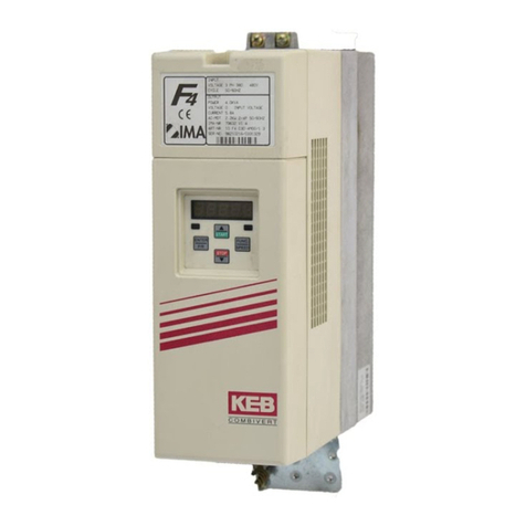
KEBCO COMBIVERT F4-F User manual

10/98
00.F4.L1B-K140
KEB COMBIVERT F4-F Lift Aufzugstechnik
Version 1.4 (Lift-Servo) Lift Technology
BETRIEBSANLEITUNG
INSTRUCTION MANUAL
ANTRIEBSTECHNIK

Information
Hilfe
Tip
Gefahr
Warnung
Vorsicht
Achtung,
Unbedingt
beachten
Diese Betriebsanleitung
– ist gültig für den Frequenzumrichter KEB COMBIVERT F4-F Lift
Version 1.4
– muß jedem Anwender zugänglich gemacht werden
Die in dieser Betriebsanleitung verwendeten Pictogramme ent-
sprechen folgender Bedeutung:
Vor jeglichen Arbeiten muß sich der Anwender mit dem Gerät
vertraut machen. Darunter fällt insbesondere die Kenntnis und
Beachtung der Sicherheits- und Warnhinweise. Lesen Sie des-
halb unbedingt die "Technische Dokumentation Teil 1".
Information
Help
Tip
Danger
Warning
Caution
Attention,
observe at
all costs
The pictographs used in this manual mean:
This manual
– is valid for frequency inverter KEB COMBIVERT F4-F Lift
Version 1.4
– must be made available to every user
Before working with this unit you must familiarize yourself with
it. Pay special attention to the safety and warning guides. Make
sure to read ‘Technical Documentation Part 1’.
DSeite D - 3 ......... D - 64
GB Seite GB - 3 ......... GB - 64

ANTRIEBSTECHNIK
GB 3
GB
1. Operating Specifications............................................................ 4
1.1 Application................................................................................................................. 4
1.2 Protective Separation ................................................................................................ 4
1.3 Inteference Protection of Electric Systems ............................................................. 4
1.4 Inteference Protection of Frequency Inverters......................................................... 4
2. Summary....................................................................................... 5
3. Inputs/Outputs.............................................................................. 6
3.1 Terminal X2 — ControlTerminals ............................................................................ 6
3.2 Terminal X3 — I/O-Expander .................................................................................... 7
3.3 Function of the Digital Inputs .................................................................................. 8
3.4 Function of the Digital Outputs / Relay Outputs.................................................. 10
4. Drive Curves ............................................................................... 12
4.1 Activation of the Main Drive................................................................................... 12
4.2 Activation of the Door Drive .................................................................................. 14
4.2.1 Control of a 2nd Motor for the Door Drive ............................................................ 14
4.2.2 U/f-Curve Door Drive .............................................................................................. 14
4.2.3 ACC and DEC Ramps ............................................................................................. 14
4.2.4 Set Speed Door Drive ............................................................................................. 14
4.2.5 Drive Curve Door Drive .......................................................................................... 15
5. Change in the Operating Frequency......................................... 16
5.1 Temperature Dependent Changes in the Operating Frequency ......................... 16
5.2 Digital Output X3.14 Operating FrequencyWarning ............................................. 16
6. Connection................................................................................. 17
6.1 Wiring Diagram:ControlTerminal X2 and I/O-Expander X3................................. 17
6.2 Connection X4 — Incremental Encoder................................................................. 18
6.2.1 Connection Incremental Encoder........................................................................... 19
6.2.2 Connection SIN/COS Encoder................................................................................ 19
6.2.3 Connection Resolver ............................................................................................... 20
6.3 Connection X5 - Incremental Encoder Emulation................................................. 20
7. Operation.................................................................................... 21
7.1 Digital / Interface Operator...................................................................................... 21
7.2 Parameter Identification .......................................................................................... 22
7.3 Parameter Selection ................................................................................................ 22
7.4 Changing ParameterValues.................................................................................... 23
7.5 Parameter Structure ................................................................................................ 23
7.6 Storing ParameterValues........................................................................................ 24
7.7 Error Messages........................................................................................................ 24
8. Parameter Description .............................................................. 25
8.1 LF-Parameters ......................................................................................................... 25
8.2 ru-Parameters .......................................................................................................... 50
8.3 In-Parameters........................................................................................................... 54
9. Start-Up Assistance .................................................................. 57
9.1 Initial Start-Up.......................................................................................................... 57
9.2 Adjustment Instructions for Conventional Lift Motors..........................................59
10. Supplement................................................................................ 60
10.1 New functions fromVersion 1.4.............................................................................. 60
10.2 Control instructions ................................................................................................ 60
10.3 Parameter list........................................................................................................... 61
10.4 Customer application parameter ............................................................................ 64
Table of Contents

GB 4
GB
1. Operating Specifications
The frequency inverter KEB COMBIVERT F4-F Lift Version 1.4 is a
drive component, which is specified for lift technology. The frequency
inverterisexclusivelyforsteplessopenloop/closedloopspeedcontrol
of three-phase asynchronous motors and permanent magnet motors.
The operation of other electrical consumers is not permitted and can
lead to the destruction of the unit.
1.1 Application
1.4 Interference Protection
of the Frequency
Inverter
Thecontrolandpowerinputsofthefrequencyinverter
are protected against interferences.
For more operational reliability and additional
protection against malfunctions take notice of
these measures:
– Use of mains filter, when the mains voltage is affected by the
connection of large consumers (reactive-power compensation
equipment, HF-furnaces etc.)
– Protectivewiringofinductiveconsumers(solenoidvalves,relays,
electromagnets) with RC elements or similar devices to absorb
the energy when the unit is switched off.
– Install wires, as described in the connection directions, to avoid
inductive and capacitive coupling of interference pulses.
Paired-twistedcablesprotectagainstinductiveparasiticvoltages,
shieldingprovidesprotectionagainstcapacitiveparasiticvoltages.
Optimal protection is achieved with twisted and shielded cables
when signal and power lines are installed separately.
! see also Instruction Manual part 2 !
1.3 Interference Protection
of Electric Systems Thefrequencyinverter KEBCOMBIVERTtransmitselectromagnetic
wavesofhighfrequency.Toreducearisinginterferencepulses,that
may effect electric systems in the vicinity of the frequency inverter,
do the following:
– Install the frequency inverter in metal housing
– Shielded motor cables must be used
TheshieldmustbeconnectedontothefrequencyinverterPEand
tothehousingofthemotor(connectextensiveshield).Donotuse
the shielding as protective earthing. The shield can only operate
safely when the shield is not interuppted and is as close as
possible to the frequency inverter and motor.
– Good earthing (metal ribbon-cable or 10 mm2earth lead)
– Use radio interference suppression filters
1.2 Protective Separation The connections of the terminal strip and encoder
inputs are safely isolated in accordance with VDE
0100. The person who installs the system/machine
must make sure that the wired circuit, whether new
or old, meets the VDE requirements.

ANTRIEBSTECHNIK
GB 5
GB
START
STOP
ENTER
F/R FUNC.
SPEED
2. Summary
9-pole sub-D socket
parameter interface
! Operator only
optional !
see page E 21
X4
15-pole sub-D socket
connection incremental encoder
X5
9-pole sub-D socket
incremental encoder simulation
X2
terminal strip
connection control terminals
X3
terminal strip
connection I/O-expander

GB 6
GB
3. Inputs/Outputs
3.1 Terminal X2
Control Terminals
Terminal Function
1 Control Release
2 Reset digital inputs:
3 Direction of travel forward noise immunity: 2 kV
4 Direction of travel reverse logic 1: ± 12…30 V
5 Control Mode internal input resistor: approx. 2 kΩ
6 Door drive active PNP-logic
7 Door drive setpoint input
8 Digital output signal: braking control see page E 10
9 Digital output signal:main protection control inverted see page E 10
10 + 18 V voltage output +18V (+/- 20%) ; max. 20 mA
! When external voltage is connected to
11 Ground for X2.10 and digital inputs/outputs terminal X2.23 then UX2.10 ≈≈
≈≈
≈UX2.23 !
12 +10 V reference voltage +10V (+/- 3%) ; max. 6 mA
13 Ground for analog inputs/outputs
14 Differential voltage input / resolution: 12 Bit
Analog setpoint input (see parameter LF.2) Ri = 40 kΩ
15 Smoothing time: 2 ms / processing time: 1...3 ms
16 Analoginputoftheprecontrol torque
(seeparameterLF.30andLF.67)
17
Option ! do not connect !
18 Analog output set speed -10V…+10V / resolution: 8 Bit Ri = 100 Ω
conditional short-circuit proof( <1 min )
19 Analogoutput actual speed 0...10V =0...2 x synchronous speed
20 30 VDC / 1 A
21 Relay control cabinet fan control (LF.66) see page E 17
22
23 External voltage supply + 24 ... + 30 V external voltage input
for digital outputs on terminal strip X2
^

ANTRIEBSTECHNIK
GB 7
GB
3.2 Terminal X3
I/O-Expander
Terminal Function
1 Digital input signal: contactor control (see page GB 9) max.voltageendurance to ground:100V
2 Setpoint input control speed: VBdigital inputs for setpoint activation
3 Setpoint input positioning speed: VE
! only valid with LF.2 = 2 !
4 Setpoint input rated speed: VNmax. voltage endurance to ground: 100V
5 Setpoint input inspection speed: VI
6 Setpoint input intermediate speed 1: V1terminal assignment with binary coded
7 Setpoint input intermediate speed 2: V2set value selection, see page GB 24 - GB 25
8
Option ! do not connect !
9 + 24 V external voltage input
External supply voltage
10 for relay outputs on terminal X3
11 Ground for X3.9/X3.10
12
13 Signal:ready/overspeed ≈UX3.9/X3.10 / 500 mA see page GB 10
14 Signal:switchingfrequencywarning ≈UX3.9/X3.10 / 500 mA see page GB 10
15 30 V DC / 1A seepageGB10
Relay contact: braking control
16
17 Signal:delaycontrol ≈UX3.9/X3.10 / 500 mA see pageGB11
18 Relaycontact: positioning speed 30 V DC / 1A see page GB11
19
20 Signal:maincontactortriggering 30 V DC / 1A see page GB11
21
22 Signal:DCmonitoring ≈UX3.9/X3.10 / 500 mA see page GB 11
23 Signal:motortemperaturewarning ≈UX3.9/X3.10 / 500 mA see page GB 11
3. Inputs/Outputs

GB 8
GB
3. Inputs/Outputs
3.3 FunctionoftheDigitalInputs
Terminal Description
X2.1 Control Tocontrol thepower modulestheinput musthave+24V. Iftheinput isnot
Release set, the inverter shows the message „nOP“ (no operation).
!Observe the operating sequence of the inputs/outputs!
see also ‘Control of the main drive’ page GB 12 - GB 13
and ‘Control instructions‘ page GB 60
X2.2 Reset With the falling edge of a +24V pulse, the error message (E.xxx) is reset.
Exception: The error message „E.OS" (error, overspeed) and „E.EnC“
(error, encoder) can only be reset by switching off the inverter.
X2.3 Direction of Whenthe inputisset at+24Va clockwiserotatingfield isproducedon the
Travel Forward output side. The inverter shows the direction of travel in the indication
(F.xxx). The set speed has a positive display. Whether the cabin moves
upor down,depends onthe phasesequence ofthe motorwiring andhow
the hoist is set up in the machine room.
Note: If the entries for forward (X2.3) and reverse (X2.4) are
simultaneouslyset,the input forward haspriority. Tochange
the direction of travel you can only use one input (X2.3).
Ifnodirectionoftravelisselectedandtheinputcontrolrelease is set, then
LS (low speed) appears in the display.
X2.4 Direction of When the input is set at +24 V, a reverse rotating field is produced on the
Travel Reverse output side.The inverter shows the direction of travel in the indication
(r.xxx).Thedisplayofthesetspeedhasanegativesign.Whetherthecabin
moves up or down, depends on the phase sequence of the motor wiring
and how the hoist is set up in the machine room.
Note: If the entries for forward (X2.3) and reverse (X2.4) are
simultaneously set, the input forward has priority. A change
of direction is done with input (X2.3).

ANTRIEBSTECHNIK
GB 9
GB
Terminal Description
X2.5
Control Mode
Inactivating theinput youcan switchfrom openloop operationto speed
controlled operation.
! only when LF.30 = 1 !
X2.6
Door Drive
In addition to the main drive the inverter can also start a door drive. The
Active
activation of the input causes the switching from the main drive to door
drive. For settings, functions and drive curves of the door drive
see pages GB 14 - GB 15 !
X2.7
Door Drive
Whenthe inputis set with+24 Vthe set valueof thedoor drive isactivated.
Setpoint Input
The set speed of the door drive is preset in parameter LF.46. For
settings, functions and drive curves of the door drive see page
GB 14 - GB 15 !
X3.1
Contactor Control
The input X3.1 checks to see if the main contactor and the braking
contactor are released. The input must be activated when a drive
command is entered. If the input is not set, the display “S.Co” (Error,
contactor open) appears in parameter LF.98. The power modules are
blocked.
The contactor control can be simulated, by bridging input X3.1 with
output X2.9.
X3.2
Correction
When the input is assigned +24 V the correction speed is activated.
Speed
VB! also see parameter LF.40 !
X3.3
Crawl Speed,
VEWhen the input is assigned +24 V the crawl speed is activated.
! also see parameter LF.41 !
X3.4
Rated Speed,
VNWhen the input is assigned +24 V the rated speed is activated.
! also see parameter LF.42 !
X3.5
Inspection Speed,
When the input is assigned +24 V the inspection speed is activated.
VI! also see parameter LF.43 !
X3.6
1st Intermediate
When the input is assigned +24 V the 1st intermediate speed is activated.
Speed,
V1! also see parameter LF.44 !
X3.7
2nd Intermediate
When the input is assigned +24 V the 2nd intermediate speed is activated.
Speed,
V2! also see parameter LF.45 !
Motor Temperature De-
Terminal motor-PTC !
tectorTerminalsOH/OH
see also page GB 11, terminal X3.23
3. Inputs/Outputs

GB 10
GB
3.4 Function of the Digital Outputs / Relay Outputs
After the voltage is switched on several digital outputs need approximately 2s for initialization. All
switching thresholds have 12% hysteresis, exept for output X3.22 which has 6%.
Exception: Output X3.22 has 6% hysteresis.
Terminal Description
X2.8
Braking
The output is activated when the following conditions are met:
Control
- no error message is present
- a setpoint must be selected (VX≠ 0 m/s)
- the contactor control input (X3.1) must be set
- the control release (X2.1) must be activated
- a direction of travel (X2.3/X2.4) must be selected
- a motor current must flow (hardware test);
The output is reset when one of the following conditions is met:
- overspeed is recognized
- a fault signal occurs
- after the setpoint values are removed the operating point of the brake
(LF.60) is gone below
- 5 s after the setpoint values are removed
X2.9
Main Contactor
The output signal corresponds to the inverted signal of terminal X3.20.
Control
When the function of the contactor control is not used, input X3.1 must be
inverted
bridged with output X2.9, to simulate the contactor control.
X2.20
Relay
How the relay output is switched depends on the temperature level set
X2.21
Control Cabinet
(parameter LF.66).
X2.22
Fan Control
actual heat sink temperature > LF.66 Relay releases
actual heat sink temperature < LF.66 - 5 K Relay picks up
! see wiring diagram page GB 17 !
X3.13
Ready for
The output is set, after the inverter has completed an internal check (after
Operation
the voltage is switched on). The output is reset, when the supply voltage is
Common Error
switchedoff,whenaninverterdisturbanceoccursorwhenoverspeedisde-
Overspeed
tected.
Note: The overspeed detection only works when the encoder is
connected, the speed controller (LF.30 ≠0 ) is switched on and
a valid speed is selected. When overspeed is reached the
inverterstops andthe errormessage "E.OS" (Error,overspeed)
isshown.Theoutputsforcontactorcontrolandbrakingarereset.
3. Inputs/Outputs

ANTRIEBSTECHNIK
GB 11
GB
Terminal Description
X3.14
Operating
The output is reset, when the heat sink is approx. 50°C warm.
Frequency
For the next drive the operating frequency is reduced to 8 kHz.
Warning
After cooling down (heat sink temperature approx. 40°C) the operating
frequency increases to 16 kHz and the output is set again.
! see operating frequency page GB 16 !
X3.15
Braking
The output emits the signal applied on terminal X3.16.
Control
See description of terminal X2.8 regarding operating frequencies.
X3.17
Delay
TheoutputissetuntilthespeedlevelLF.62isgonebelow.Thefunctiononly
Control
works when the incremental encoder is connected and when the speed
controller is switched on (LF.30 ≠0).
X3.18
Crawl
Theoutput emitstheapplied signalonterminal X3.19.Thisis doneuntilthe
Speed
preset speed level in parameter LF.63 is gone below. This function only
workswhenthe incrementalencoder isconnectedandthe speedcontroller
is switched on (LF.30 ≠0).
X3.20
Main Contactor
The ouput emits signals that are applied to terminal X3.21. The output
occurs,
Control
when the following conditions are met at the same time:
- no error message is present
- setpoint must be selected
- the input contactor control must be activated
X3.22
DC-Voltage
The output is set, when the dc-bus voltage exceeds the level LF.64.
Monitoring
X3.23
Motor
The output is reset, when the connection between the “OH” inputs is high-
Temperature
resistant. This is how the lift control receives the message that the motor is
Warning
overheating. It then can stop driving and let the motor cool down. If the
overheating continues, the inverter switches off, when the delay time set in
LF.65 has run out. The error signal “E-dOH” (Error, drive overheat) is
displayed. When the connection between the OH terminal is low resistant
again,theinvertershowsthemessage“E.nOH”(nooverheat).Theerrorcan
then be reset. See parameter LF.15
3. Inputs/Outputs

GB 12
GB
t
X3.3
X2.4
X2.3
X3.17
X3.20
X3.15
X3.18
X3.4
X3.1
X2.1
v
LF.62
LF.63
LF.60
LF.50
LF.51
LF.50
LF.42
LF.61
LF.52
LF.53
LF.52 LF.54
LF.53
LF.54
LF.41
123456 7 8 9 10 11 12 13
4.1 Activation of the Main Drive (LF.02 = 2)
InputsOutputs
Operating Points
4. Drive Curves

ANTRIEBSTECHNIK
GB 13
GB
WHAT HAPPENS WHEN?
Description of the Operating Points of the Main Drive
1: Presetting of the setpoint for the drive speed and the selection of the direction
of travel.The inverter checks whether input X3.1 (contactor control) is set. If
yes the output X3.20 (main contactor control) is set. If X3.1 is not set, the
display “E.Co“ is seen in LF.98 and output X3.20 is not set.
2: If X3.20 is set, then X3.1 must be reset.
3: X2.1 (control release) is set with the precontrol contact of the main contact.
After this is done the inverter provides the motor with current, when the main
contacts are connected (powerless switching).
When the safety Circuit is interrupted input X2.1 must be reset immediately.
(see „Control instructions“ page GB 60)
4: Whenthemotorcanreceiveacurrent(“hardwaretest”),theoutputX3.15(brake)
is set. If there is not enough current flowing, you will see the display “E.nC” in
LF.98 and X3.15.
5: AfterX3.15 isset, thebrakerelease time (LF.70)runsout;thenthe motorstarts
toturn.
6: When exceeding the monitoring of the crawl speed (LF.63) the output X3.18 is
reset.
7: When exceeding the monitoring of the deceleration check (LF.62) the output
X3.17 is reset.
8: When the setpoint is removed for the rated speed (X3.4) deceleration starts.
9: When exceeding the monitoring of the deceleration check (LF.62) the output
X3.17 is set.
10: When exceeding the monitoring of the crawl speed (LF.63) the output X3.18 is
set.
11: When the limit switch is reached, the set value for the positioning speed is set
at 0 and thus the drive keeps the cabin floating until the brake is engaged,.
12: Whenthe operatingpoint of thebrake(LF.60) isexceeded, the outputX3.15 is
reset.
13: When X3.15 is reset, the modulation is switched off after two times of LF.70
(brake release time). 0,3 s later output X3.20 is reset.
4. Drive Curves

GB 14
GB
4.2.2 U/f-Curve
Door Drive
This function makes it possible to activate the main drive and the
door drive with one inverter. The selection of the drive is done with
the digital input X2.6.
Theswitchingbetweenmainanddoordriveis onlyaccepted in
condition ‘nop’.
The
following
is valid:
With an active door drive (X2.6 = 1)
- The outputs of the inverter are not changed
- The start up process cannot be completed
- Onlythecontrolledmodeisactive(U/f-curve).Thecontrolmethod
(LF.30) is only valid for the main drive.
4.2.1 Activation of a 2nd
Motor for the Door
Drive
For the ACC and DEC ramps of the door drive the values of
parameters LF.50, LF.51, LF.53 und LF.54 are valid, like with the
main drive.
The set speed (rpm) for the door drive is preset in parameter LF.46
(set speed door drive). The setpoint activation for the door drive is
done with the digital input (X2.7).
The U/f-curve of the door drive is defined by parameters LF.25,
LF.26, LF.27,and LF.28. The setting of parameters for the U/f-
curves of the main and door drives is only possible when the
main drive is active (X2.6 = 0).
Rated voltage [V] LF.28
LF.26 Rated speed
LF.27 Rated voltage
Torque increase [%] LF.25 f [Hz]
n [rpm]
U [V] / U [%]
4.2.3 ACC and DEC Ramps
4.2.4 Set Speed Door Drive
4. Drive Curves
4.2 Activation of the Door Drive
X2.6 Active Drive Control Process
0 Main Drive set as in LF.30
1 Door Drive controlled

ANTRIEBSTECHNIK
GB 15
GB
t
X2.4
v
LF.46
12
LF.50
LF.51
LF.50
LF.54
LF.53
LF.54
X2.6
X2.3
X2.1
X2.7
Inputs
Operating Points
What happens when?
Description of the operating points of the door drive.
1: The acceleration process starts after the setpoint input is activated (X2.7 = 1).
Condition: Door drive is active (X2.6)
Control release is active (X2.1)
Direction of rotation (X2.3 / X2.4) is preset
2: When the setpoint for (X2.7) is removed deceleration begins.
4. Drive Curves
4.2.5 Drive Curve Door Drive

GB 16
GB When the heat sink temperature reaches approximately 50°C, the
signal at output X3.14 (operating frequency warning) is reset. With
a heat sink temperature of approx. 40°C the signal at the output is
set again.
5. Changes in the Operating Frequency
To protect KEB COMBIVERT F4-F Lift from overheating during
16kHzoperation andthuspreventtheliftfrombeinginterrupted,the
operating frequency can be reduced dependent on the heat sink
temperature (only in condition ‘nop’). Inverters with temperature
dependent operating frequencies are characterized in parameter
In.0 with xx.F4.F1.-xxxx 8kHz/16kHz.
!see also parameter LF.38!
5.1 Temperature Dependent
Changes in the Operating
Frequency
5.2 Digital Output X3.14
Operating Frequency
Warning

ANTRIEBSTECHNIK
GB 17
GB
6. Connection
6.1 Wiring Diagram: Control Terminal X2 and I/O-Expander X3
X2.8 Braking control
Deceleration control
Positioning speed
Main contactor control
Relay contact
DC-monitoring
Operatingfrequencywarning
Digital Outputs:
Control release
Direction of travel reverse
Contactor control
Reset
Direction of travel foward
Digital Inputs:
Re-levelling, VB
Inspection speed, VI
Inspection speed 1, V1
Inspection speed 2, V2
Positioning, VE
Rated max. speed, VN
Setpoint selection
(only with LF.2 = 2)
Supply
With binary coded setpoint selection
(LF.2 = 1), terminal assignment see
page GB 25 - GB 26
X2.9
X2.1
X2.2
X2.3
X2.4
X2.5
X2.6
X2.7
X3.1
X3.2
X3.3
X3.4
X3.5
X3.6
X3.7
Secondary drive setpoint input
Control mode
Secondarydriveactive
Braking control
Main contactor control inverted
X3.15
X3.16
X3.18
X3.19 Relay contact
Ready
X3.20
X3.21
X2.20
X2.21
X2.22
X3.13
X3.14
X3.17
X3.22
X3.23
Relay contact
Heatsinktemperature >LF.66
(5 K hysteresis)
Heatsinktemperature<LF.66
Relay contact
Motor temperature warning
X3.9
X3.10
X2.23
X2.11
X3.11
X3.12
Ground (GND)
Ground (GND)
+24V (control card)
+24V (I/O-card)
+24V (I/O-card)
Ground (GND)
Relay Outputs:

GB 18
GB
12345 67
8
9
10 1112131415
The incremental encoder of the motor is connected to the 15-pole
sub-D-socket.
6.2 Connection X4
Incremental
Encoder
Theconnector may onlybeconnected / disconnected
when the inverter and voltage supply are shut off.
Encoder Specification:
1- Voltage Supply: + 5 V (+/-10 %) max. 110 mA
2- Increments: 256 - 10000 inc. (recommended: 2500 inc.)
Observe limit frequency of encoder:
increments • nmax
flimit > ————————
60
Input Wiring
A +
B +
A -
B -
121Ω
10 kΩ
10 kΩ
10 nF
6. Connection
6.2.1 Connection
Incremental Encoder
PIN-No. Signal PIN-No. Signal
1- 9B+
2-10-
3 A - 11 + 15 V
4 B - 12 + 5 V
5 - 13 GND
6-14N-
7-15N+
8 A + housing shield

ANTRIEBSTECHNIK
GB 19
GB
A+
B-
B+
A-
A+
B-
B+
A-
12345 67
8
9
10 1112131415
or sinusoidal 1 Vss signals
Two sinusoidal incremental signals that are
electrically by 90° out of phase and their inverse
signals
3- Output signals: Rectangular pulse signal
Two square-wave pulses that are electrically by
90° out of phase and their inverse signals
2...5 V
0 V
U0 + 0,5 V (+/-20 %)
U0 - 0,5 V (+/-20 %)
U0 ⇒approx. 2.5 V
6. Connection
PIN-No. Signal PIN-No. Signal
1 C - 9 B +
2D-10
3A-11
4 B - 12 + 5 V
5 13 GND
6C+14R-
7D+15R+
8 A + Housing Shield
6.2.2 Connection
SIN/COS Encoder
Theconnector may onlybeconnected / disconnected
when the inverter and voltage supply are shut off.

GB 20
GB
12345
6789
12345 67
8
9
10 1112131415
The 9-pole sub-d-socket is used as an incremental encoder output.
The signals are emitted corresponding to the signals on the
incremental encoder input X4 in RS422 specifications.
! see also parameter LF.3 !
6. Connection
Theconnector may onlybeconnected / disconnected
when the inverter and voltage supply are shut off.
PIN-Nr. Signal PIN-No. Signal
1 9 COS
2 10 SIN_REF
3 SIN_LO 11
4 COS_LO 12
5 SIN_REF_LO 13
6 14
7 15
8 SIN Housing Shield
6.2.3 Connection
Resolver
6.3 Connection X5
Incremental Encoder
Emulation
PIN-No. Signal Meaning
1 A + SignalChannellA
2 B + SignalChannelB
3 reserved
4 + 5 V Voltageoutput
5 + 24 V externalvoltagesupply
6 A- invertedSignalChannel A
7 B- invertedSignalChannell B
8 reserved
9 GND external Mass
Housing Shielding
Other manuals for COMBIVERT F4-F
3
Table of contents
Other KEBCO Lifting System manuals