manuals.online logo
Brands
  1. Home
  2. •
  3. Brands
  4. •
  5. Altronix
  6. •
  7. UPS
  8. •
  9. Altronix ReServ2 User manual

Altronix ReServ2 User manual

ReServ2 -1-
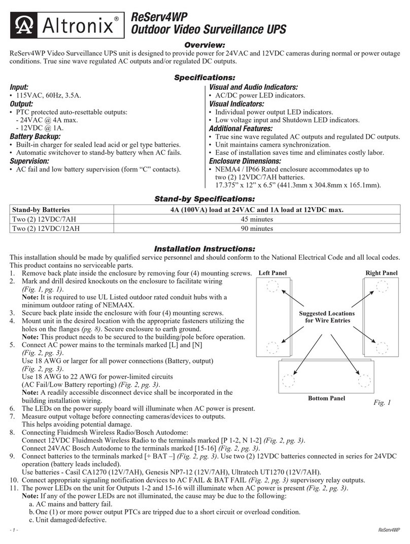
Overview:
ReServ2 Video Surveillance UPS is designed to provide power for 24VAC cameras during normal or power outage
conditions. True sine wave regulated AC outputs.
Specifications:
Input:
• 115VAC 60 Hz, 1.9 amps.
Output:
• 24VAC outputs.
• Sixteen (16) PTC protected outputs.
• 4 amp (100VA) total supply current.
Output Ratings:
•PTC protected outputs are rated @ 1 amp.
Battery Backup:
•Built-in charger for sealed lead acid or gel type batteries.
•Automatic switchover to stand-by battery
when AC fails.
Visual Indicators:
• Individual power LED indicator.
• AC input power output LED indicators.
Visual Indicators (cont’d):
• Low battery and output power shutdown LED indicators.
Supervision:
• AC fail supervision (form "C" contacts).
• Low battery supervision (form "C" contacts).
Special Features:
• True sine wave regulated AC output.
• Audible alarm provides notification of
UPS trouble conditions.
• Unit maintains camera synchronization.
• Ease of installation saves time and eliminates costly labor.
Enclosure:
• Enclosure accommodates up to two (2)
12VDC/7AH batteries.
•Dimensions: 13.5"H x 13"W x 3.25"D
Installation Instructions:
This installation should be made byqualified service personnel and should conform to all local codes and in accordance
with the National Electrical Code. Product is intended for indoor use only. This product contains no serviceable parts.
1. Mount unit in desired location. Mark and predrill holes in the wall to line up with the top two keyholes in the
enclosure. Install two upper fasteners and screws in the wall with the screw heads protruding. Place the enclosure’s
upper keyholes over the twoupper screws, level and secure.
Mark the position of the lower twoholes. Remove the enclosure. Drill the lower holes and install the two fasteners.
Place the enclosure’supper keyholes over the two upper screws. Install the two lower screws and make sure to tighten
all screws (Enclosure Dimensions, pg. 4).Secure enclosure to earth ground.
2. Connect AC power mains to terminals marked [L & N], connect ground to terminal marked [G] (Fig. 1f, pg. 2).
Use 18 AWG or larger for all power connections (Battery, output) (Figs. 1b & 1d, pg. 2).
Use 18 AWG to 22 AWG for power limited circuits (AC Fail/Low Battery reporting) (Fig. 1c, pg. 2).
3. LED on the ReServ2B board will illuminate when AC power is present.
4. Measure output voltage before connecting cameras/devices to outputs. This helps avoid potential damage.
5. Connect 24VAC cameras/devices to terminals marked [1-16] (Fig. 1d, pg. 2).
6. Unit provides an audible alarm when the following conditions occur; AC fail, Low Battery, Output power shutdown.
To disable the audible alarm remove jumper (Fig. 1a, pg. 2).
7. The power LEDs on the unit for Outputs 1-16 will illuminate when AC power is present (Fig. 1d, pg. 2).
Note: If any of the power LEDs are not illuminated the cause may be due to the following:
a. ACmains and battery fail.
b. One (1) or more power output PTCs are tripped due to a short circuit or overload condition.
c. Unit damaged/defective.
To reset the PTC:
1. Disconnect corresponding camera/device connected to terminals marked [1-16] (Fig. 1d, pg. 2).
2. Eliminate the trouble condition (short circuit or overload).
3. Allow 1 minute for PTC to cool off (reset).
4. Connect corresponding cameras/devices to terminals marked [1-16] (Fig. 1d, pg.2).
5. Power LEDs will illuminate indicating power has been restored to outputs (Fig. 1d, pg. 2).
WARNING: Toreduce the risk of fire or electric shock, do not expose the unit to rain or moisture.
This installation should be made byqualified service personnel and should conform to all local codes and in
accordance with the National Electrical Code.
®
®
ReServ2
Video Surveillance UPS Rev. 100609
-2- ReServ2
1
PTC2
2
PTC3
3
PTC4
4
PTC5
5
PTC6
6
PTC7
7
PTC8
8
PTC9
9
PTC10
10
PTC11
11
PTC12
12
PTC13
13
PTC14
14
PTC15
15
PTC16
16
5A 250V
PTC17
SHUTDOWN
LOW BAT
AC
F1
NO C NC NO C NC
AC FAIL BAT FAIL
L G N
AC
BAT
--- +
Green
Lead
115VAC
power mains
non-power
limited
12VDC Rechargeable Battery 12VDC Rechargeable Battery
Note: Two (2) rechargeable batteries required.
(order separately)
Green
Lead
Fig. 1
SHUTDOWN
LOW BAT
AC
NO C NC NO C NC
AC FAIL BAT FAIL
BAT
--- +
Fig. 1a
SHUTDOWN
LOW BAT
AC
NO C NC NO C NC
AC FAIL BAT FAIL
BAT
--- +
Fig. 1b
PTC2
PTC3
PTC4
PTC5
PTC6
PTC7
SHUTDOWN
LOW BAT
AC
NO C NC NO C NC
AC FAIL BAT FAIL
BAT
--- +
Fig. 1c
1
PTC2
2
PTC3
3
PTC4
4
PTC5
5
PTC6
6
PTC7
7
PTC8
8
PTC9
9
PTC10
10
PTC11
11
PTC12
12
PTC13
13
PTC14
SHUTDOWN
LOW BAT
AC
NO C NC NO C NC
AC FAIL BAT FAIL
BAT
--- +
Fig. 1d
15
PTC16
16
5A 250V
PTC17
F1
L G N
AC
Green
Lead
115VAC
power mains
non-power
limited
Note: Two (2) rechargeable batteries required.
(order separately)
Green
Lead
Fig. 1e
PTC11
11
PTC12
12
PTC13
13
PTC14
14
PTC15
15
PTC16
16
5A 250V
PTC17
F1
L G N
AC
Green
Lead
115VAC
power mains
non-power
limited
Fig. 1f
Fig. 1b
Fig. 1c
Fig. 1d
Fig. 1f
Fig.1e
Fig. 1a
ReServ2 -3-
Stand-by Specifications:
Terminal Identification:
LED Diagnostics:
Stand-by Battery 4amp (100VA) max. load at 24VAC
2 - 12VDC/7AH 45 minutes
2 - 12VDC/12AH 90 minutes
Terminal Legend Function/Description
L, G, N Connect 115VAC to these terminals: L to Hot, N to Neutral, G to ground (if used).
1-16 24VAC outputs.
AC Fail
NO, C, NC
Used to notify loss of AC power, e.g. connect to audible device or alarm panel. Relay normally
energized when AC power is present. Contact rating 1 amp @ 28VDC.
Battery Fail
NO, C, NC
Used to indicate low battery condition, e.g. connect to alarm panel. NO, C, NC Relay normally
energized when DC power is present. Contact rating 1 amp @ 28VDC.
Low battery threshold:
24VDC output threshold set @ approximately 21VDC.
--- B A T + Stand-by battery connections. Maximum charge rate .5 amp.
LED LED State Description
AC (Green) ON ----- Normal operating condition.
----- OFF Loss of AC. Stand-by batteries are supplying power.
24VAC Power Outputs
(Red)
ON ----- Normal operating condition.
----- OFF Loss of 24VAC output power.
Low Battery ON ----- Stand-by batteries are low.
----- OFF Normal operating condition.
Shutdown ON ----- Loss of 24VAC output power. Discharged stand-by batteries.
----- OFF Normal operating condition.
- 4 - ReServ2
Altronix is not responsible for any typographical errors. Product specifications are subject to change without notice.
140 58th Street, Brooklyn, New York 11220 USA, 718-567-8181, fax: 718-567-9056
web site: www.altronix.com, e-mail: [email protected], Made in U.S.A.
IIReServ2 J06I MEMBER
Enclosure Dimensions:
13.5"H x 13"W x 3.25"D
5.10"
6.5625"
3.25"3.25"
5.10"
5.10"
3.25"
1.00"10.50"1.00"
1.00" 1.00"
1.40"
1.20"
1.40"
1.20"
0.75"0.75" 11.00"
12.50"
3.25"
0.9375"
0.9375"
1.40" 4.85" 4.85" 1.40"
1.20"
Bottom
Top
RightLeft

Other Altronix UPS manuals

Altronix ReServ Series User manual

Altronix

Altronix ReServ Series User manual

Altronix ReServ1 User manual

Altronix

Altronix ReServ1 User manual

Altronix ReServ1WPV User manual

Altronix

Altronix ReServ1WPV User manual

Altronix ReServ4WPV User manual

Altronix

Altronix ReServ4WPV User manual

Altronix RESERV ReServ5WP User manual

Altronix

Altronix RESERV ReServ5WP User manual

Altronix ReServ1 User manual

Altronix

Altronix ReServ1 User manual

Altronix ReServ1WPV User manual

Altronix

Altronix ReServ1WPV User manual

Altronix ReServ1WP User manual

Altronix

Altronix ReServ1WP User manual

Altronix Maximal series User manual

Altronix

Altronix Maximal series User manual

Altronix ReServ4WP User manual

Altronix

Altronix ReServ4WP User manual

Popular UPS manuals by other brands

Cross FP3000 user manual

Cross

Cross FP3000 user manual

FEAS LDR8024-RS Supplementary instructions

FEAS

FEAS LDR8024-RS Supplementary instructions

BPC PowerStar series 1200 user manual

BPC

BPC PowerStar series 1200 user manual

MGE UPS Systems Pulsar Evolution 1500 Installation and user manual

MGE UPS Systems

MGE UPS Systems Pulsar Evolution 1500 Installation and user manual

Eaton Powerware 9125 user guide

Eaton

Eaton Powerware 9125 user guide

ABB MegaFlex UL S1 Series user manual

ABB

ABB MegaFlex UL S1 Series user manual

EPE EPS-2000 Series owner's manual

EPE

EPE EPS-2000 Series owner's manual

Eaton Powerware 9395 Installation and operation manual

Eaton

Eaton Powerware 9395 Installation and operation manual

Kohler PW 6000 user manual

Kohler

Kohler PW 6000 user manual

Minuteman MCP 1000 user manual

Minuteman

Minuteman MCP 1000 user manual

socomec DIRIS Digiware 2018 quick start guide

socomec

socomec DIRIS Digiware 2018 quick start guide

iTrust UH11-0060 user manual

iTrust

iTrust UH11-0060 user manual

Energizer ER-HT400 Specifications

Energizer

Energizer ER-HT400 Specifications

CyberPower UP625 user manual

CyberPower

CyberPower UP625 user manual

Bicker Elektronik UPSI-2406DP1 user manual

Bicker Elektronik

Bicker Elektronik UPSI-2406DP1 user manual

inform Guard 500VA user manual

inform

inform Guard 500VA user manual

Tecnoware ERA LED 0.85 user manual

Tecnoware

Tecnoware ERA LED 0.85 user manual

ALLTRONIC One V9 1K RT user manual

ALLTRONIC

ALLTRONIC One V9 1K RT user manual

manuals.online logo
manuals.online logoBrands
  • About & Mission
  • Contact us
  • Privacy Policy
  • Terms and Conditions

Copyright 2025 Manuals.Online. All Rights Reserved.