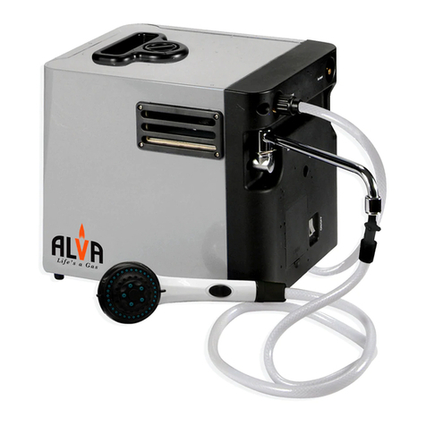
Alva GWH108 User manual


Please read the
instructions carefully
before use.
Retain this manual for
future reference.
IMPORTANT SAFETY INFORMATION
As with all gas appliances, misuse of this appliance or failure to fully follow
these instructions may cause re, injury or death. Please read all the
instructions before using your gas heater.
• Never use this appliance in an enclosed area such as a camper, tent or
car.
• THIS UNIT MUST BE THOROUGHLY CHECKED BEFORE USE.
• Ensure that all the gas ttings are correctly and rmly tted before every
use.
• DO NOT use this appliance if you do not clearly understand the
instructions and/or how to operate the controls.
• Phone the customer care line at 086 100 ALVA (2582) or email
info@stingray.co.za for assistance.
• DO NOT leave the appliance unattended while in use.
• Ensure that the gas supply is turned OFF after use and while the
appliance is unattended.
• DO NOT move the appliance while in use.
• DO NOT place objects on or against the appliance.
• DO NOT use a naked ame to test for leaks. Follow the Leak
Testing procedure outlined under ‘LEAK TEST’.
• NEVER use this appliance with a cylinder other than the size
recommended
• DO NOT unscrew the regulator while the appliance is on or if the cylinder
valve is open.
• DO NOT use an appliance you suspect is faulty.
• When turning the appliance off, rst turn the gas down (LO) at the control
valve (on the heater) and then make sure to close the cylinder valve.
• For safety reasons, only a qualied technician may execute maintenance
and repairs. The guarantee for the heater will be rendered void if the
heater is serviced or repaired by any one other than an Alva appointed
technician.
• The appliance should be inspected once a year by a qualied technician,
to make sure the unit is safe and fault free.
• The operator is responsible for the safety of all third parties while the
appliance is in use.
• DO NOT store or use gasoline or other liquids with ammable vapours in
the vicinity of this or any other appliance.
• If used on boats, use only above deck.
• Always use the appliance in an upright position.
• Keep children and pets away from the burner at all times.
• DO NOT operate the appliance under any overhead construction.
• Keep a minimum clearance of 1m from the sides, front and back of the
appliance.
• Use only on a level, stable, non-combustible surface like bricks or
concrete
• Keep the fuel supply hose away from any heated surfaces.
• Should overheating occur or the gas supply fails to shut off, turn off the
gas supply at the cylinder.
• DO NOT obstruct ow of combustion and ventilation to or from the
appliance.
• This appliance will be hot during and after use. Use insulated oven
gloves or mitts for protection from hot surfaces.
• Always allow the appliance to cool before covering.
• Always cover the appliance when not in use.

IMPORTANT INFORMATION FOR THE USER
This appliance may only be installed by a registered SAQCC Gas installer. All
registered installers are issued with a card carrying their registration number.
Ask to be shown the card before allowing the installation work to commence
and make a note of the Installer registration number. Upon completion of the
installation, the installer is required to explain the operational details of the
appliance together with the safety instructions. You will be asked to sign
acceptance of the installation and be provided with a completion certicate.
You should only sign for acceptance of the installation when the installation is
completed to your satisfaction.
Note that your invoice is required in the event that you wish make a guarantee
claim.
IMPORTANT INFORMATION FOR THE INSTALLER.
This appliance may only be installed by a gas installer registered with the South
African qualication and certication committee (SAQCC). The appliance must
be installed in accordance with the requirements of SANS 10087-1 for use with
LPG, SANS 827 for use with NG and any re department regulations and/or
local bylaws applicable to the area. If in doubt, check with the relevant authority
before undertaking the installation. Upon completion of the installation you are
required to fully explain and demonstrate to the user the operational details and
safety practices applicable to the appliance and the installation.
CAUTIONS
(a) Don’t use the water heater in the sealed room or poorly ventilated place.
(b) The exhaust pipe must be installed to discharge exhaust gas outside.
(c) During operation, if you nd out there is a gas leakage, you should close the
gas valve immediately. The cause of the gas leakage should be tested and
the service center or gas company must be contacted.
(d) Before leaving the house or going to sleep, please be sure to shut off the
gas supply.
(e) Do not place any objects at the exhaust port or air inlet to avoid poisoning
caused by incomplete combustion.
(f) During operation, please pay attention to combustion situation. If there is an
abnormal combustion, you should close the gas valve immediately and then
contact the service center or gas company for maintenance.
(g) When the outdoor temperature drops below zero and freezing may
occur, the remaining water should be discharged out of heater after using it.
Water should be discharged in the following steps: turn off the gas supply
valve – turn off the tap water supply valve - remove the water discharge
valve to discharge remaining water entirely - re–install the water discharge
valve.
(h) The body of the water heater can get very hot during operation, so please
don’t touch any part of the water heater except for the switches.
(i) While using the water heater constantly, please pay attention to the
temperature of the water owing out initially so as to prevent from being
scalded.
(j) Check the gas pipe and rubber hose regularly. If you nd out joints are not
tight or there are cracks in the hose, you should stop using and make timely
maintenance or replace with a new one.
Please read the
instructions carefully
before use.
Retain this manual for
future reference.

INDEX
INDEX
WARRANTY
GENERAL INFORMATION
METHOD OF ASSEMBLY
WATER HEATER SET UP
FLASHBACK
LEAK TEST
FUNCTIONS & FEATURES
TECHNICAL PARAMETERS
INSTALLATION INSTRUCTIONS
INSTRUCTIONS FOR DAILY MAINTENANCE
MAINTENANCE
FREQUENTLY ASKED QUESTIONS
TROUBLE SHOOTING GUIDE
SPECIFICATIONS
AFTER SALES SERVICE
2
2
3
3-4
4
5
6-8
9
10-12
13
14
14-15
16-17
18-19
19
KEY
Important information
Cautions and
warnings.
Danger
Contact an approved
ALVA technician.
Do It Yourself

WARRANTY
PLEASE RETAIN YOUR PROOF OF PURCHASE FOR
WARRANTY CLAIMS.
ALVA warrants this appliance to be free of defects in material and
quality for a period of 12 months from date of original purchase.
This warranty covers the intended use of this appliance – within
a domestic setting and not for commercial or industrial purposes.
Any damage caused by wilful abuse, tampering, modication or
unauthorized repair will not be warranted.
Please retain all packaging material, as items returned without
original packaging material may be subject to a withholding fee.
Where this appliance is found to be defective, damaged, broken,
or does not work correctly for the intended purpose, you must
return the appliance to the retailer where it was purchased. The
warranty will only be effected with valid proof of purchase. Failure
to provide the proof of purchase will most likely result in the
repair or service required being chargeable.
If you have any questions while setting up or using this heater,
please visit www.alva.co.za or call 086 100 ALVA (2582) or e-mail
info@stingray.co.za
GENERAL INFORMATION
Before using this appliance, please read through this manual and
make sure you understand everything. If you are not sure, please
call 086 100 2582 or visit www.alva.co.za for help.
This appliance is a safe and efcient form of heating when used
according to these instructions.
Keep this manual for future reference. This manual should be
read in conjunction with labeling on the product.
If this product is not what you want or need, please help Alva and
the environment by not damaging or destroying any part of the
packaging, the manual or the Styrofoam inserts. Always keep
your proof of purchase.
Keep these instructions for future use. If you lose this copy, you
can obtain a new copy from your dealer or online at
www.alva.co.za
Thank you for your
purchase of this
portable water heater.
Please read these
instructions carefully
before use and keep
them in a safe place,
for future reference.
Not using gas and/
or gas appliances
according to the
instructions is
extremely dangerous
and can lead to
property damage,
injury or death.
2

WATER HEATER SET UP
Setup using mounting brackets
This appliance may be mounted on to a non-combustible
surface. The appliance is to be mounted using the supplied
hardware. For a temporary mount the unit can be suspended
from the top bracket. If being mounted permanently the appliance
should be mounted using both the bottom and top tabs.
3
Outlet hose and shower head
assembly
Attach the shower nozzle to the
hose. Make sure to insert the
supplied rubber gasket at the
connection.
Connect the opposite end of the
hose to the brass tting on the
bottom of the appliance labeled
“Water Output”. Make sure to insert
the supplied rubber gasket at this
connection.
Hand tighten only.
Rubber Gasket
Rubber Gasket
Rubber Gasket
An additional brass tting for con-
necting a garden hose included. If
connecting a garden hose to the
output, rst connect the brass tting
using the supplied gasket to the
brass tting on the bottom of the
appliance labeled “Water Output”.
Hand tighten only. Ensure the
garden hose has a rubber gasket
inserted in the connector.
Attach a standard garden hose
to the tting on the bottom of the
appliance labelled “Water Input”.
Make sure to insert the supplied
rubber gasket at the connection.
Rubber Gasket
Optional garden hose connector to output
Water supply input assembly

4
Battery Installation
Install 2 ‘Type D’ cell batteries in the compartment on the bottom
of the appliance. Make sure the batteries are installed in the
correct direction.
Clean the battery and device contacts prior to battery installation.
Always purchase the correct size and grade of battery.
DO NOT mix new and old batteries. Replace all batteries at the
same time.
Connecting the regulator to the appliance
This tting must be held with
a crescent or 7/8” end wrench
when tightening or loosening
the regulator hose.
Attach the gas regulator to the
appliance. The regulator will attach
to the brass tting on the bottom of
the appliance labeled “Gas Input”.
Tighten the ttings using wrenches
on both the brass adaptor tting on
the appliance and the brass tting
on the end of the hose
Use 2 adjustable wrenches of 3/4”
and 7/8” wrenches for tightening
the hose to the brass valve of the
appliance.
WARNING
Attempting to tighten
the hose tting the ap-
pliance without using
a wrench on the brass
adaptor tting on the
bottom of the appli-
ance could damage
the product and cause
a gas leak. Damage
may occurr to the unit
if tightened improperly.
FLASHBACK
In the event of ash back whilst the Water Heater is in use, turn
all the controls a to the ‘OFF’ position. Wait 5 minutes before
attempting to relight the Water Heater. If the problem persists,
check for blocked ventury ports by removing the burner and
cleaning with compressed air or with a pipe cleaner. Check under
burner cap or aeration adjustment - Restart Water Heater.
If problem persists do not try to rectify the problem yourself as
this could result in serious injury and/or property damage.

• If bubbles appear, turn the cylinder valve OFF (clockwise)
and disconnect the heater from the gas cylinder.
• Tighten the connection and retry the leak test.
• If you are unsure or if you cannot tighten the connection,
place the cylinder outside in a cool, well-ventilated area and
contact Alva on 086 100 ALVA (2582).
• A leak between the heater and cylinder can lead to a high
pressure re, which is very dangerous and can result in
extensive injury or even death.
LEAK TEST
The leak test must be carried out in a well-ventilated area, free
from any ames or other sources of ignition.
• With the cylinder connected to the heater. Open the cylinder
valve.
• Brush the connections (heater to cylinder) with a solution of
equal parts soap and water (make sure it’s foamy).
• A stream of bubbles forming indicates a gas leak. (See
Fig.D)
• If bubbles appear, turn the cylinder valve OFF (clockwise)
and disconnect the heater from the gas cylinder.
• Tighten the connection and retry the leak test
Fig.G
Foamy
bubbles
indicate a
leak
Connection
in assembly
Connections to be leak tested
Regulator into cylinder
Hose to regulator
Hose to appliance
5
DO NOT insert any
foreign objects into the
valve outlet. You may
damage the valve and
cause a leak.
A leak may result in
a property damage,
injury or even death.
NEVER attempt to
attach this appliance to
the self contained gas
system of a camper,
trailer or motor home.

6
http://www.
youtube.com
/watch?v=8L
pZ1B0m23Y
&feature=plcp
How to do
a leak test
FUNCTIONS & FEATURES
Water controlled automatic ignition:
If the hot water tap is switched on, the unit will automactically
ignite and deliver hot water to the tap.
Auto cut-off protection:
Numerical control automatic ignition, the auto cut-off protection
will extinguish the gas supply immediately.
Energy saving:
Advanced combustion system with the Winter/Summer switch,
in winter strengthen ame and in summer reduce ame, hence
more comfortable and energy saving.
Low water pressure startup function:
When water supply pressure is lower to 0.025Mpa, the unit can
also startup, suitable to the user living in high rise building or
lower water supply pressure.
Anti-freezing protection:
When temperature is very low, remove the water discharge valve
to discharge accumulated water inside the water pipe to avoid
damage caused by freezing.
Anti-dry combustion protection:
Once dry combustion occurs, the protection device will shut off
the gas supply automatically.

Over-pressure protection:
Once water pressure is over 1.0Mpa, the unit will relieve the pressure
automatically to avoid damage.
PLEASE SEE THE OUTLINE APPEARANCE AS FOLLOWS:
7

CONSTRUCTION & NAME OF EACH PART - FLUE DUCT TYPE
8

TECHNICAL PARAMETERS
INSTALLATION INSTRUCTIONS
A. CAUTIONS:
1. The water heater must be installed in the well-ventilated place and the exhaust pipe must
be mounted to discharge exhaust gas. During operation the water heater consumes lots of
oxygen, so the air inlet hole must be made in the room above the height of 0.06 square
meters and the exhaust pipe shall be mounted.
• Poor air circulation and no exhaust pipe will cause lack of oxygen. Carbon monoxide
poisoning, death and all such serious accidents can arise due to incomplete combustion.
2. Don’t expose the water heater to strong wind or rain.
3. Only LPG appointed gas on the nameplate or specication must be used.
• The misusing of gas can cause deagration or re. Carbon monoxide poisoning, death
and all such serious accidents can arise due to incomplete combustion.
4. Don’t use aged or cracked rubber pipe.
5. The water heater should not be installed near combustible or volatile substances.
6. Be sure the water pressure is not lower than 0.025Mpa.
7. The water heater should’nt be installed above burning appliances, such as a cooking
oven.
8. The water heater shouldn’t be installed near stairs or any safety exit (except for
beyond 5m).
9
GWH108
GWH1012
GWH1016

10
B.INSTALLATION INSTRUCTIONS
1.Installation of the water heater body:
(a) Drill four 8mm holes according to the dimensions shown on the drawing 8, and put in
6mm expansion bolt (if the dimensions has changed, please use the actual unit to mark
the necessary wholes)
(b) Hang the water heater, then x it with expansion bolt at the hole of lower bracket.
See the Drawing 9.
There must be air, an air inlet
and an exhaust outlet

2.Installation of pipes
(a).Connection of the cold water supply pipe:
• The cold water inlet joint is G1/2 pipe thread.
• The water inlet pipe must be connected by using metal tube, or by rigid water pipe.
• The inner diameter of the inlet pipe (including the valve) shouldn’t be less than 8mm.
• The cold water valve should be installed with the water inlet pipe.
• Please ensure that the lter in the cold water inlet is mounted correctly.
Clean the new pipes by ushing with water. Make sure there are no blockages, then
insert the rubber gasket and x the water inlet joint tightly.
(b).Connection of the hot water supply pipe:
• The hot water outlet joint is G1/2 pipe thread.
• The hot water outlet pipe must be connected by metal tube or by rigid water
pipe or by rubber pipe with sprayer directly.
• The inner diameter of the hot water pipe outlet pipe (including the valve) shouldn’t be
less than 8mm.
(c). After installation, please open the cold water valve to the maximum to test the ow of
water and check whether there is water leakage.
(d). Installation of the gas supply pipe:
• The gas inlet joint has a G1/2 pipe thread. Make sure that the gas inlet pipe joint and
rubber gasket is connected. The special soft rubber tube can be used according to the
technical parameters. Securely t the pipe with the clip. Note: Gasket must be inserted,
otherwise you will experience a gas leak.
• After the gas inlet joint is connected, open the gas supply valve, and check whether
there is a gas leak at the joint with soapy water.
• Liquied petroleum gas users should use a good quality low pressure adjusting valve
with a ux above 0.6m/h.
3.Installation of exhaust device:
(a) According to the outline dimension of the attached ue pipe, make a hole with the
diameter a little larger then the ue pipe at a suitable position to easily install the ue pipe
horizontally easily.
(b) The installation of the ue is shown in the
Drawing 10. The total height of the exhaust pipe
should be more than 2.3 meters and the
horizontal length must not exceed 3 meters.
There must be a vertical ascending ue pipe and
the hole should not be less than 250mm above
the exhaust pipe cover. The gap between the
ue pipe and the hole should not be lled with
cement, otherwise repairs will be difcult.
(c) Install an exhaust fan not lower than the top of the
water heater.
11

12
(d) Make a air inlet door not less than 0.06 square meters on
the downside of the wall.
(e) When a wall is made of inammable material, the clapboard
must be installed between the ue pipe of the water heater
and the wall ( the thickness is about 20mm).
(f) If the ue pipe is connected with a funnel, the entry part
of the ue pipe must be as short as possible and the joint
with the funnel must not leak at all.
C. OPERATING INSTRUCTIONS
1.Operation:
(a) Open the cell box and put in two Type D batteries.
(b) Open both the cold water valve and hot water valve. Close
the water inlet valve after you make sure the cold water is
owing out through the water outlet and the ignition pins
discharge.
(c) Start gas supply.
(d) Shoul the unit not ignite, this is a direct cause from a
airlock in the pipe - Try 2 or 3 times.
(e) All the water heaters have the seasonal switching
operation to meet your requirements for suitable
temperature.
(f) Close the water inlet or water outlet valve, the water heater
will stop working. If needed again, just re-open the water
inlet valve or water outlet valve. Please note that the
temperature of the hot water owing out is higher at that
moment, so excercise caution.
(g) Close the water inlet valve or water outlet valve, the water
heater will be turned off immediately, then shut off the
main gas supply.

INSTRUCTIONS FOR DAILY MAINTENANCE
1. Check the gas supply pipe (rubber hose) regularly to see if it is
in good condition, or there should be no aging, cracking,
leakage or bends.
2. Please regularly check if there is water leakage or gas
leakage.
3. Please regularly clean surface of water heater body to remove
dirt or dust with a wet cloth, and then use the dry cloth to wipe
off the moisture. If not easy to remove, please use a natural
detergent to wipe off.
4. For the plastic section, printed surface or spraying surface, it
is not suitable to use strong detergents, benzene or gasoline
to clean them.
5. Please use a dry cloth to clean the dirt on the ignition, to
ensure a good start up.
6. Remove and wash the stainless steel lter in the cold water
inlet regularly.
7. During the operation, please pay attention to the height of the
ame to see if it is good condition. Check the heat exchanger
and combustor searching for dust or dirt every half a year.
All servicing must be done by a registered technician.
13

14
MAINTENANCE
• Always make sure the heater is
OFF and cool, with the cylinder
valve closed, before conduct-
ing any maintenance.
• Your heater should be checked
once a year by a qualied
technician.
• If faults are suspected or
detected, stop using the heater
and contact ALVA.
• Clean the exterior and stor-
age area of your heater when
required to remove dust and
prevent lint build up.
• DO NOT use abrasive products
to clean the heater; these may
damage the paint work.
• Clean the exterior body with a
damp cloth.
If any part of the heater is in need of replacing, use only original
Alva parts. Using any other spare parts is dangerous and will
void the warranty.
FREQUENTLY ASKED QUESTIONS
Q: Why is there an odour when I use a gas heater?
A: All gas appliances give off an odour. This could be
harmful if inhaled for extended periods of time. This
“smell” is normal, and it does not mean that you have
a gas leak. The smell of raw gas (just before you ignite
the appliance) differs to the smell coming from the
appliance when it is in use. The odour is added to allow
easy gas detection.
IF YOU SMELL GAS
1. Do not attempt to
light appliance
2. Extinguish any
open fame
3. Disconnect from
fuel supply
Clean the entire
appliance annually and
tighten all hardware
on a regular basis (1-2
times a year or more
depending on usage).
Fig.K
Core
GOOD
BAD
Not enough air
BAD
Too much air

Q: Why must there be ventilation when using a gas
appliance?
A: Whenever fuel (LP Gas in this case) is burned,
ventilation is needed. Any re needs oxygen to burn.
Think of a replace, you require a chimney or ue for
the smoke to exit the house. Even though a gas
appliance does not generate smoke, it still generates
carbon monoxide and carbon dioxide, which can be
dangerous if not diluted by fresh air.
ventilation by leaving a door or window open in the
same room.
Always ensure adequate ventilation by leaving a door
or window open in the same room.
Q: How long will the gas in my cylinder last?
A: This depends on how you use your appliance. It is easy
to calculate your gas consumption. Take the capacity of
the gas cylinder in grams (i.e. 3000g for a 3 kg
cylinder) and divide it by the gas consumption of the
heater, on your desired setting (refer to the
Specications section in this manual (page 9). The
answer to the calculation is the approximate number of
hours that your heater will burn for.
Q: What do I do if I have an over-lled cylinder?
A: The best method to determine if your cylinder is over-
lled is to weigh it. Subtract the ‘tare’ mass from the
cylinder weight – this gives you the weight of your gas.
If this gas weight exceeds your cylinder design weight
(3kg) then return the cylinder to your gas
supplier.
http://www.
youtube.com/
watch?v=Ya
vsYE8nzCw
&feature=plcp
How to test if
your cylinder
is overfilled
15

16
TROUBLE SHOOTING GUIDE
TROUBLE CAUSE REMEDY
Odour Combustion N/A - The combustion process
will always cause an odour
Strong
odour
Incorrect gas
mixture
Unburned gas
leak
Obtain LPG only from reputa-
ble LPG dealers
Perform a leak test
Always ensure there is proper
ventilation
Burns then
dies
Over-lled
cylinder
Ventilation
Empty
cylinder
Return to gas supplier
Make sure the room has ad-
equate ventilation
Replace with a full cylinder
Unit will not
ignite
(No audible
clicks at
start up)
Batteries
Not enough
water
Disconnected
wire
Debris
Make sure batteries are in-
stalled correctly
Adjust tabs in battery
compartment to ensure circuit
is complete
Make sure there is an
adequate supply of water
Make sure the water inlet is
connected to the correct tting.
Remove 1 screw from
bottom of the appliance
going through the tab on the
front cover.
Make sure the wire
terminals connected to the top
of the battery are
connected.
Reverse the water ow.
Connect water source to the
heater outlet.
If you are still unable
to correct the problem
with the information
in this guide , then
you need to contact
your nearest dealer or
manufacturer.

17
Unit will not
ignite
(Audible
clicks at
start up)
Empty
cylinder
Not enough
water
No gas ow
Make sure the LPG cylinder is
full and cylinder valve is open
Replace with a full cylinder
Make sure there is an
adequate supply of water
Make sure the water inlet is
connected to the correct tting.
Perform leak test
Remove regulator hose from
appliance tting and ensure
there are no obstructions
Unit ignites
and then
shuts off
Not enough
water
Wind
Empty
cylinder
Ignition
sensor
adjusted
incorrectly
Thermocouple
Thermostat
Make sure there is an
adequate supply of water
Make sure the water inlet is
connected to the correct tting.
Excessive winds may
extinguish the ame
Make sure LPG cylinder is full
and cylinder valve open
Replace with a full cylinder
Wires located directly above
the burner should be bent at 90
degrees and approximately ¼”
above the burner. Use a pair
of pliers to bend the wires as
needed.
Adjust thermocouple so that
it is centred in the hole on the
heat exchanger
Call 086 100 ALVA (2582)
If you are still unable
to correct the problem
with the information
in this guide , then
you need to contact
your nearest dealer or
manufacturer.
This manual suits for next models
2
Table of contents
Other Alva Water Heater manuals
Popular Water Heater manuals by other brands

MegaTech
MegaTech Solar series installation manual

Noritz
Noritz ecoTOUGH NRC98-DV-NG installation manual

STIEBEL ELTRON
STIEBEL ELTRON SHU 5 SL Operation and installation

onsen
onsen 14L manual

Noritz
Noritz N-0931M-DV-ASME owner's guide

Rinnai
Rinnai TANKLESS WATER HEATER V53E Operation and installation manual

Bosch
Bosch YS2180RA owner's guide

emmeti
emmeti EB300-S15-AS50 Instruction for installation and maintenance

STIEBEL ELTRON
STIEBEL ELTRON DHB-E 18 Si Operating and installation instructions

Lochinvar
Lochinvar 151 - 801 Operation manual

Kenmore
Kenmore 153.316040 owner's manual

TERMA
TERMA AQUAPRO WIFI 30 user manual