10
1. DESCRIZIONE DEI COMPONENTI ITIT
Acumulación de agua de calentamiento para sistemas integrados
ESES
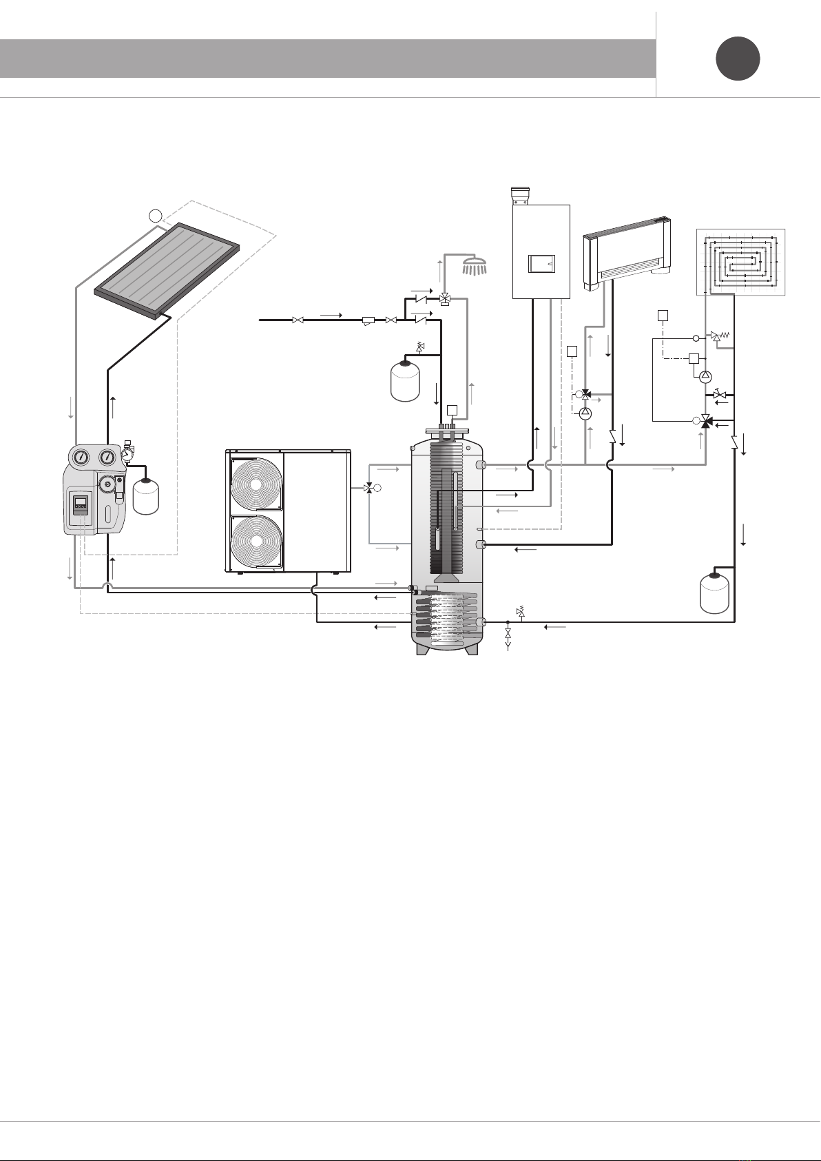
Premisa
El hervidor se diseñó para poder integrar más fuentes energéticas presentes en la
instalación de calentamiento como por ejemplo: bombas de calor, paneles solares
térmicos, caldera a gas, etc..., Constituido por:
• Un depósito para el agua de calentamiento de acero con aislamiento térmico
rígido, recubierto por una capa de pvc de color gris: poliuretano inyectado 70 mm
para el modelo eb500 con coeficiente de conductibilidad térmica de 0.025 W/mk
y reacción al fuego clase b3 din 4102;
• Serpentino inferior fijo para la conexión de los paneles solares;
• Serpentino de cobre con aletas para la producción rápida de acs, integrado, con
brida de fijación adecuada en la parte superior del depósito.
• De confomidad con el articulo 4.3 De la directiva 2014/68/ue.
Disposiciones de instalación
La instalación hidráulica y la conexión de la acumulación del agua de calentamiento deben realizarse según las normas y regulaciones vigentes en el lugar de
instalación y según las disposición del diseñador de la instalación térmica, en particular:
• Personal técnicamente especializado debe realizar las operaciones de instalación de la acumulación.
• La unidad deberá instalarse en ambientes protegidos del hielo y de agentes atmosféricos.
• La unidad debe colocarse respetando los espacios técnicos mínimos, teniendo presente el acceso a las conexiones de agua y eléctricas.
• Es necesaria la instalación de válvulas de interceptación que aíslan a la unidad del resto de la instalación, y asimismo, de los grifos de descarga de la
instalación/acumulación.
• Es obligatorio instalar un filtro de red metálica (de malla cuadrada de lado no superior a 0,8 mm) de dimensiones y pérdidas de carga adecuadas en los tubos
de entrada.
• Una correcta colocación de la unidad prevé su puesta a nivel y un plano de apoyo capaz de soportar el peso.
• Asegúrese de que presión de alimentación del agua no supere el valor de la placa de acumulación, prevea una posible reducción de presión.
• Instale las válvulas de seguridad graduadas según lo indicado en la ficha de acumulación.
• Instale los vasos de expansión correspondientes, dimensionados según la capacidad de uso de los respectivos circuitos.
• Para evitar fenómenos de corrosión o daños de la acumulación, asegúrese de que el agua y las conexiones sean compatibles con la misma. Las características
físico químicas de potabilidad del agua fría sanitaria deben ser tales que no provoquen corrosiones ni incrustaciones en el intercambiador de cobre y deben
tener una dureza inferior a 15° franceses, de lo contario, se deberá prever la instalación de un tratamiento químico adecuado (por ejemplo: ablandador).
• Dos uniones dieléctricas están parcialmente atornilladas en las conexiones de serpentina. Para garantizar una conexión de sellado adecuada,
por lo tanto, es necesario colocar un material de sellado adecuado entre la junta y la rosca del acoplamiento y luego atornillar la junta nuevamente
sobre el acoplamiento. En su caso, los tubos de conexión no están en metros metálicos. (por ejemplo, tuberías multicapa) no es necesario el uso
de juntas dieléctricas.
Características
• Compensador hidráulico
• Integración solar al calentamiento
• Integración caldera de condensación
• Integración posible bomba de calor
• Integración posible caldera a leña
• Estratificación con camino hidráulico
• Producción de agua sanitaria instantánea
• Higiene absoluta
• Larga duración
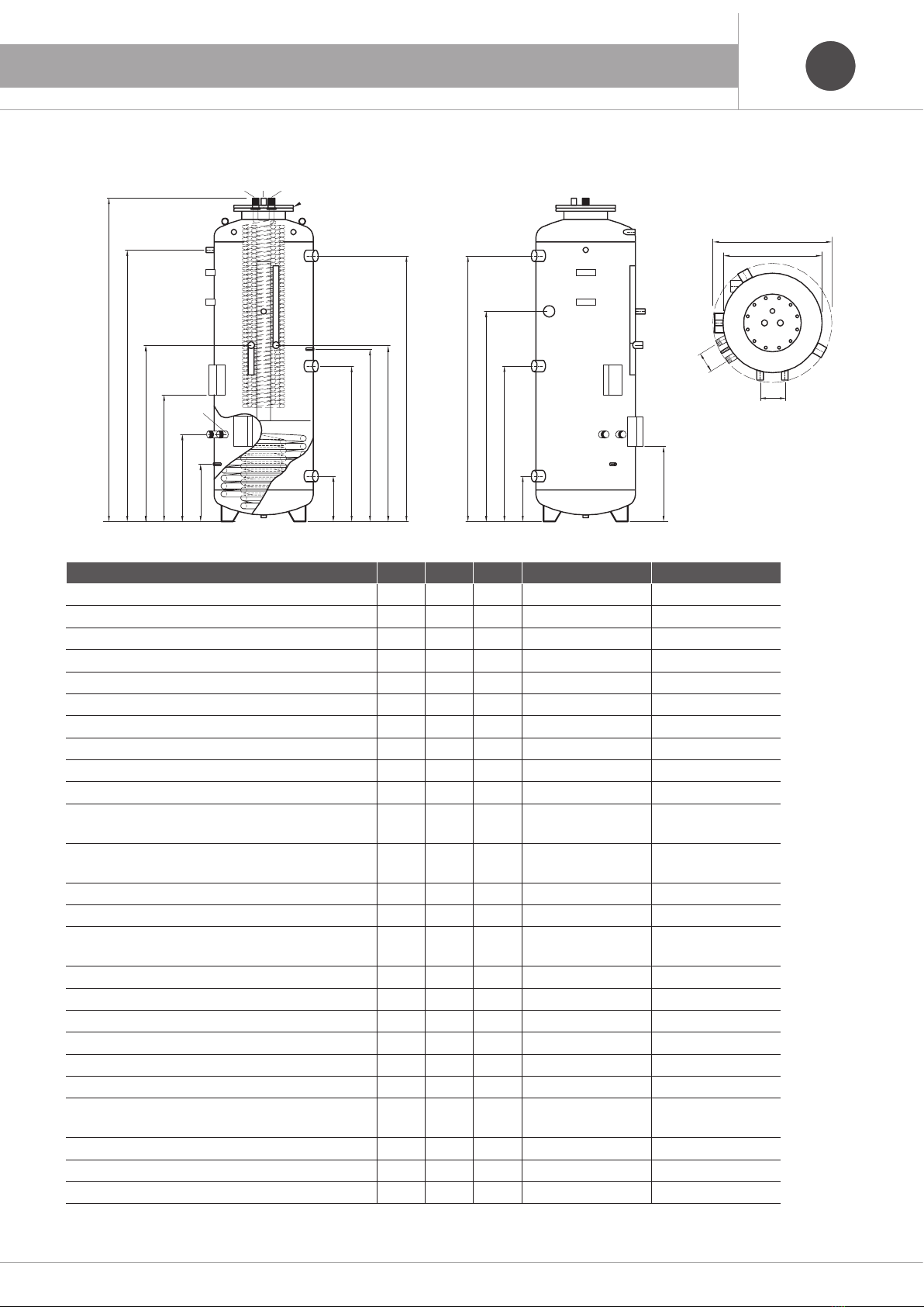
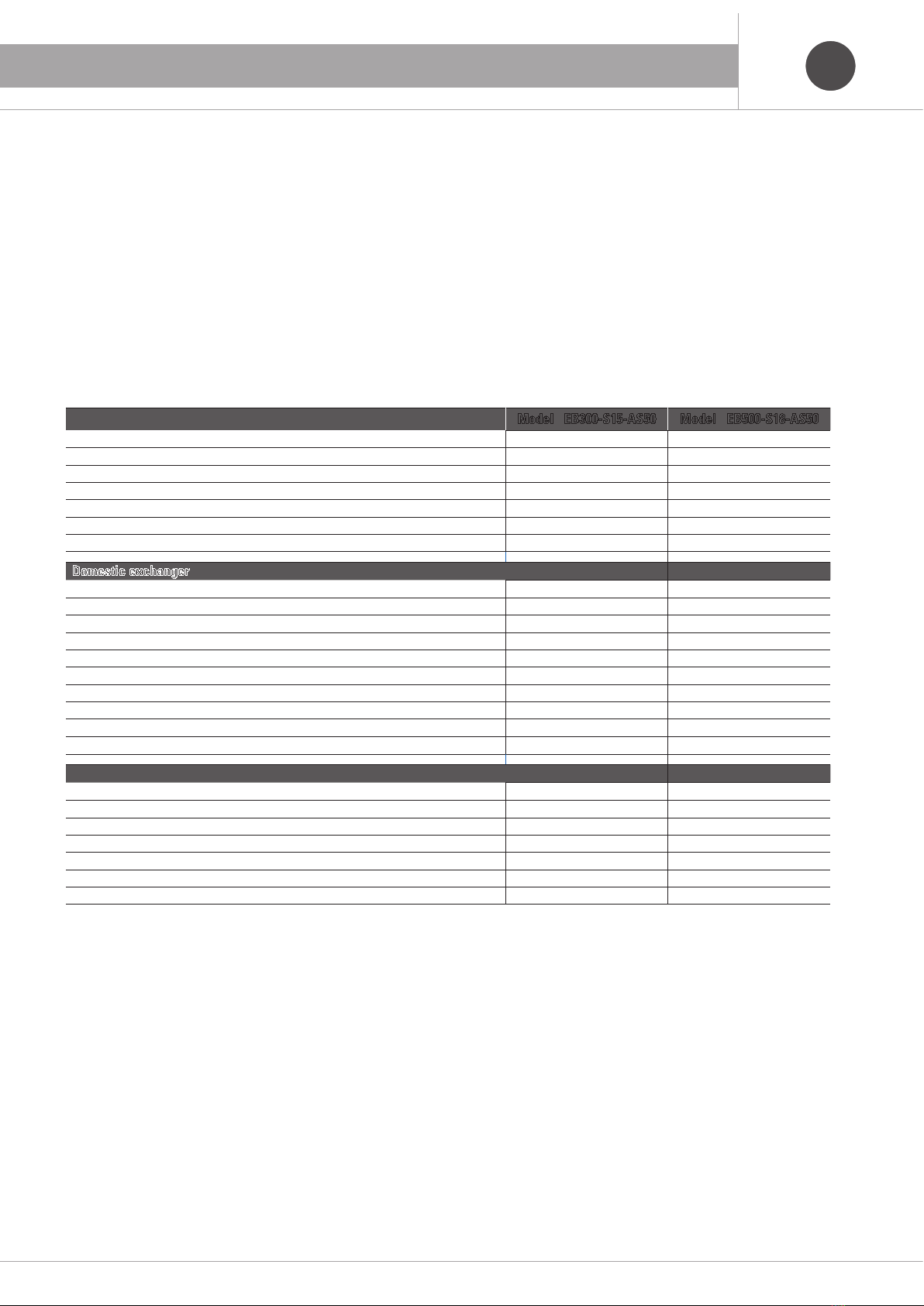
Datos técnicos Modelo EB300-S15-AS50 Modelo EB500-S18-AS50
Capacidad total de agua de calentamiento 267 ℓ467 ℓ
Diámetro externo Ø 640 mm Ø 790 mm
Altura total con aislamiento 1630 mm 1680 mm
Altura máxima en enderezamiento 1750 mm 1860 mm
Presión máxima de operación 3 bar 3 bar
Temperatura máxima de operación w 95 °C 95 °C
Peso peso en vacío 138 kg 150 kg
Intercambiador sanitario
Brida (Ø externo / interno) 300 / 210 mm 300 / 210 mm
Superficie intercambiador 5 m25 m2
Contenido agua serpentino 3,5 ℓ3,5 ℓ
Producción agua caliente sanitaria 80 / 60 °C (DIN 4708) 2,5 m3/h 2,5 m3/h
Potencia absorbida 100 kW 100 kW
Caudal necesario al serpentino 4,3 m3/h 4,3 m3/h
Pérdidas de carga 4,4 bar 4,4 bar
Coeficiente (DIN 4708) 33 NL 33 NL
Presión máxima de operación del intercambiador 10 bar 10 bar
Producción agua caliente sanitaria (entrada 15 °C / salida 40 °C / con acumulación 50 °C)
15 ℓ/min 15 ℓ/min
Intercambiador solar
Superficie intercambiador 1,4 m21,8 m2
Contenido agua serpentino inferior 8,3 ℓ10,3 ℓ
Potencia absorbida 34 kW 44 kW
Caudal necesario al serpentino 1,5 m3/h 1,9 m3/h
Producción agua sanitaria 80 / 60 °C (DIN 4708) 0,8 m3/h 1,1 m3/h
Pérdidas de carga 34 mbar 69 mbar
Presión máxima de operación del intercambiador 6 bar 6 bar


 Operation and maintenance instructions")