INSTALLATION REQUIREMENTS
Tools and Parts
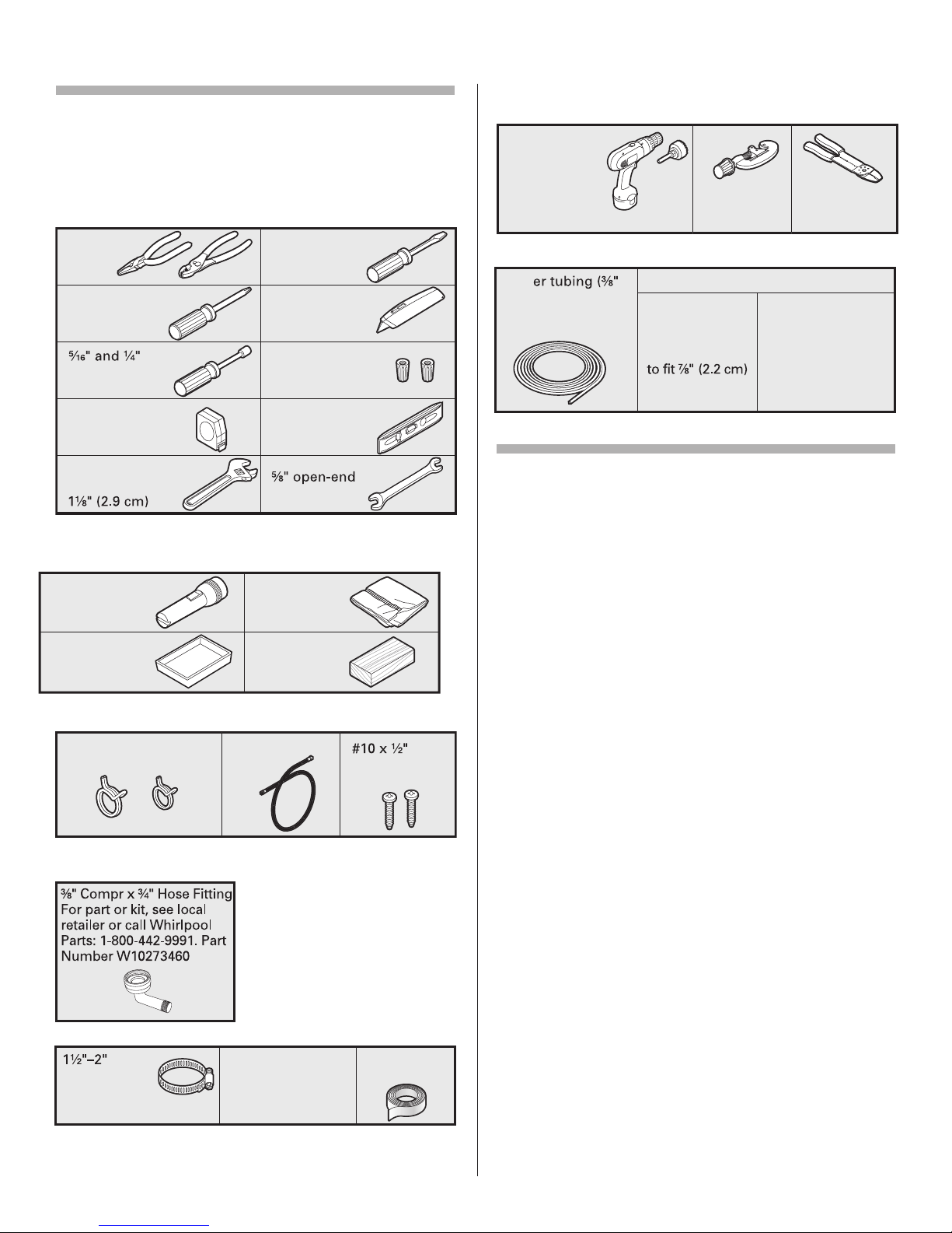
Gather the recommended tools and parts before starting
installation. Read and follow the instructions provided with any tools
listed here.
All Installations
Tools needed:
*Must be the proper size to connect your household wiring to
16 gauge wiring in dishwasher
Other useful items you may need:
Parts supplied:
Ma e sure all these parts are included in the literature pac age.
Parts needed:
Other parts you may also need:
NOTE:
Parts available for purchase in plumbing supply stores.
Chec local codes. Chec existing electrical supply. See “Electrical
Requirements” section. It is recommended that electrical connections be
made by a licensed electrical installer.
In addition, for first time installations
Tools needed:
Parts needed:
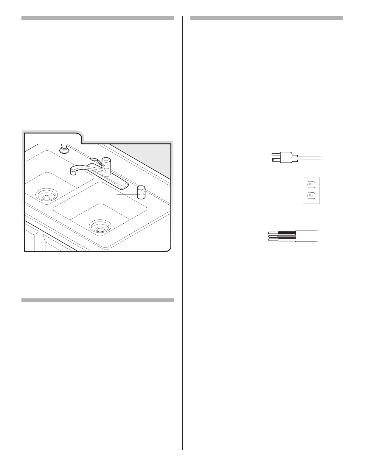
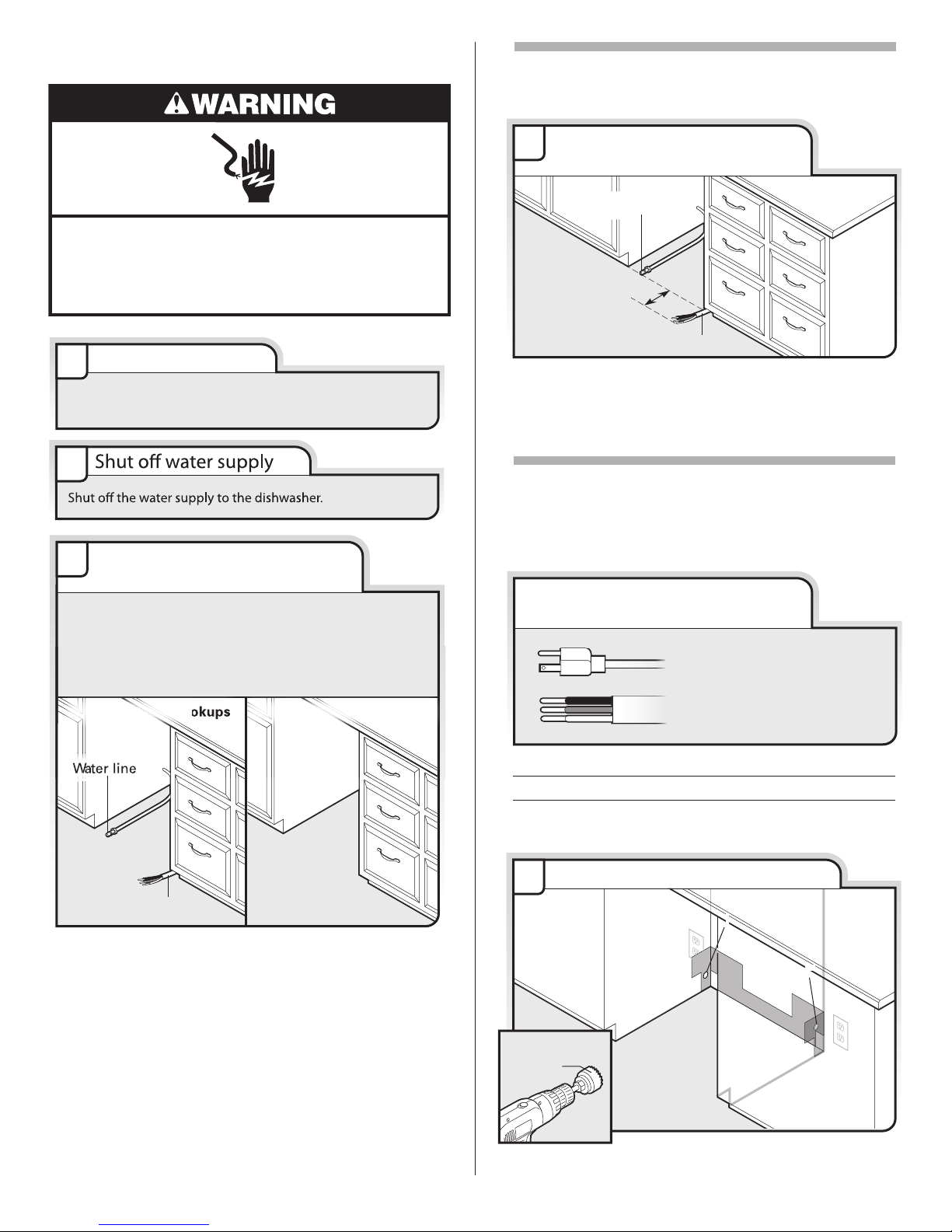
Location Requirements
Grounded electrical supply required.
Do not run drain lines, water lines or electrical wiring where
they can interfere with or contact dishwasher motor or legs.
The location where the dishwasher will be installed must
provide clearance between motor and flooring. Motor should not
touch the floor.
Do not install dishwasher over carpeted flooring.
Shelter dishwasher and water lines leading to dishwasher
against freezing. Damage from freezing is not covered by the
warranty.
A side panel it is available from your dealer for installing
your dishwasher at the end of your cabinetry.
A moisture barrier accessory (Part Number 4396277) is available
from your dealer for installing underneath the countertop.
Chec location where dishwasher will be installed. The
location must provide:
• easy access to water, electricity and drain.
• Convenient access for loading and unloading dishes. Corner
locations require a 2" (5.1 cm) minimum clearance between the
side of the dishwasher door and the wall or cabinet.
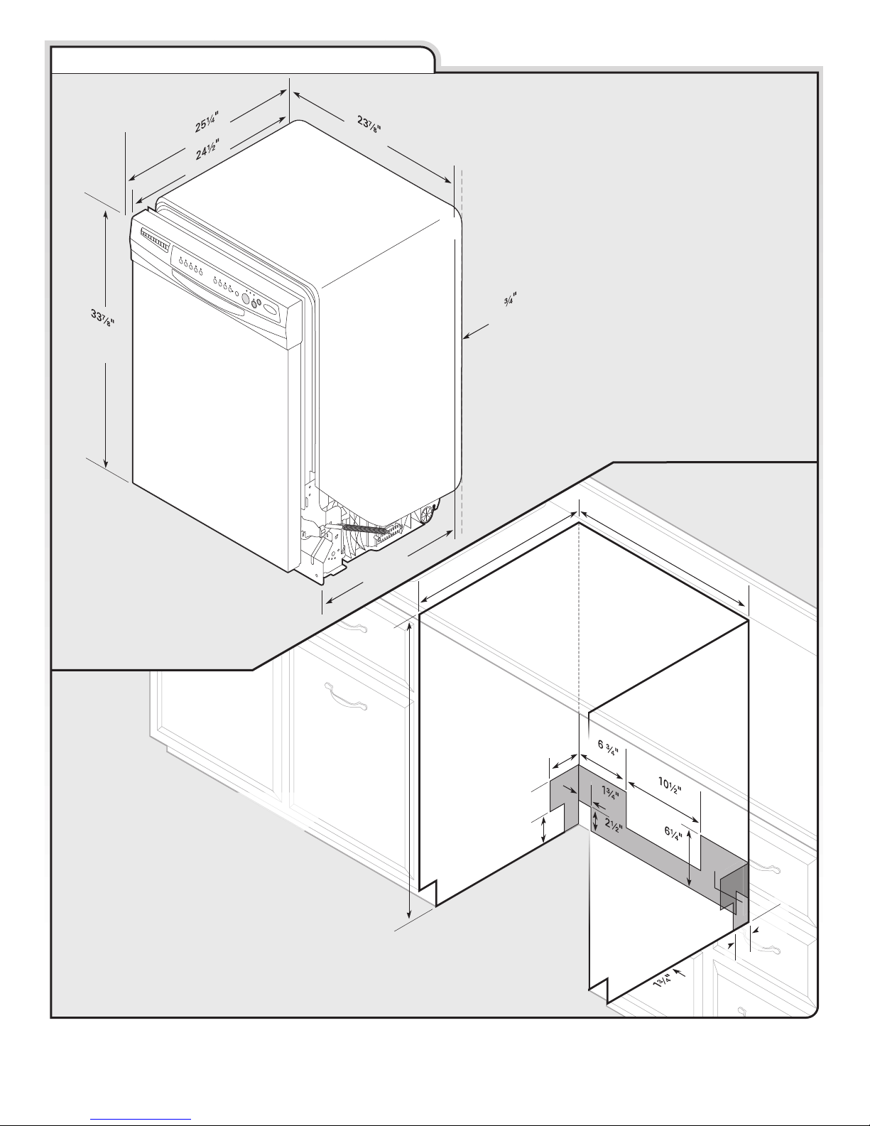
• square opening for proper operation and appearance.
• cabinet front perpendicular to floor.
• level floor. (If floor at front of opening is not level with floor at
rear of opening, shims may be needed to level dishwasher.)
Helpful Tip: Be sure to accurately measure dimensions
and ensure dishwasher is level if the floor in the dishwasher
opening is uneven (example: flooring extends only partway into
opening).
NOTE: To avoid shifting during dishwasher operation,
shims must be securely attached to the floor.
If dishwasher will be left unused for a period of time or in a
location where it may be subject to freezing, have it winterized by
authorized service personnel.
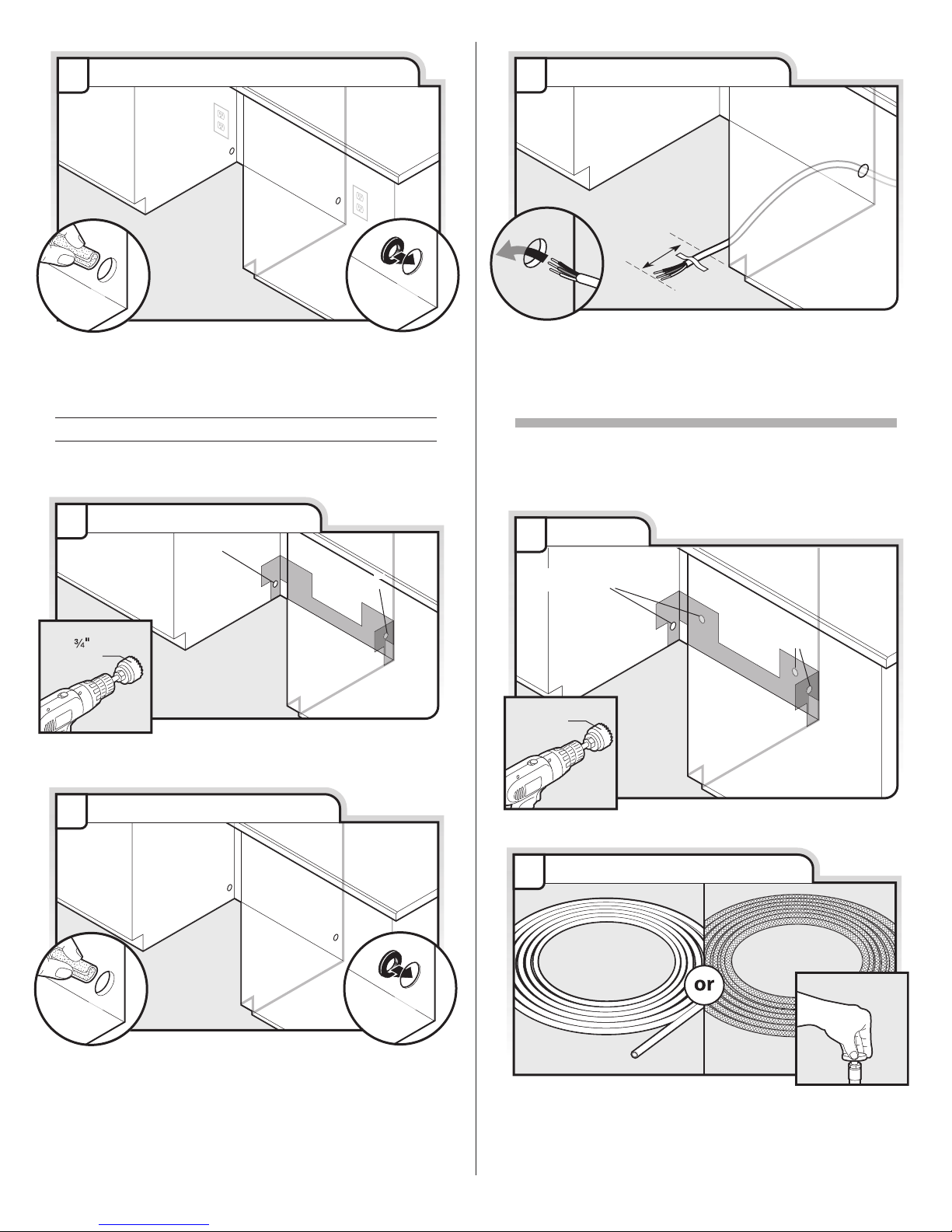
Ma e sure pipes, wires and drain hose are within the
shaded area shown in the “Product and Cabinet Opening
Dimensions” section.