manuals.online logo
Brands
  1. Home
  2. •
  3. Brands
  4. •
  5. Amana
  6. •
  7. Furnace
  8. •
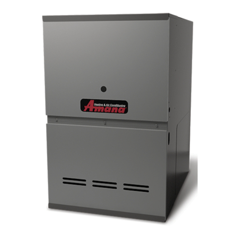
  9. Amana AMH8 User manual

Amana AMH8 User manual

Other manuals for AMH8

1

This manual suits for next models

8

Other Amana Furnace manuals

Amana M8 User manual

Amana

Amana M8 User manual

Amana AMVC8 Series User manual

Amana

Amana AMVC8 Series User manual

Amana MSS9 User manual

Amana

Amana MSS9 User manual

Amana MVC80 User manual

Amana

Amana MVC80 User manual

Amana GUI Guide

Amana

Amana GUI Guide

Amana GUIA Series Operating instructions

Amana

Amana GUIA Series Operating instructions

Amana AM9S80 User manual

Amana

Amana AM9S80 User manual

Amana MVC96 BB Series User manual

Amana

Amana MVC96 BB Series User manual

Amana M9C96 Series User manual

Amana

Amana M9C96 Series User manual

Amana GUD Series Operating instructions

Amana

Amana GUD Series Operating instructions

Amana ACSS920402BN User manual

Amana

Amana ACSS920402BN User manual

Amana GMS8 Guide

Amana

Amana GMS8 Guide

Amana GUC Series User manual

Amana

Amana GUC Series User manual

Amana ACVC96 User manual

Amana

Amana ACVC96 User manual

Amana *MEC96 User manual

Amana

Amana *MEC96 User manual

Amana AMVS96-U User manual

Amana

Amana AMVS96-U User manual

Amana M9S96 Series User manual

Amana

Amana M9S96 Series User manual

Amana *CVC96 User manual

Amana

Amana *CVC96 User manual

Amana AMVM96 User manual

Amana

Amana AMVM96 User manual

Amana AM9S96 User manual

Amana

Amana AM9S96 User manual

Amana GUCA User manual

Amana

Amana GUCA User manual

Amana AMS9 User manual

Amana

Amana AMS9 User manual

Amana GMSS9 Series Operating instructions
Amana

Amana GMSS9 Series Operating instructions

Amana GMS8 Operating instructions

Amana

Amana GMS8 Operating instructions

Popular Furnace manuals by other brands

Unitary products group AHV8 UH installation manual

Unitary products group

Unitary products group AHV8 UH installation manual

VERDER CARBOLITE GERO RHF 14/8 Installation, operation and maintenance instructions

VERDER

VERDER CARBOLITE GERO RHF 14/8 Installation, operation and maintenance instructions

Tempstar B Series Service and technical support manual

Tempstar

Tempstar B Series Service and technical support manual

Carrier Performance 59SP5A Installation, start-up, operating and service and maintenance instructions

Carrier

Carrier Performance 59SP5A Installation, start-up, operating and service and maintenance instructions

Armstrong EG7H SERIES Installation and maintenance instructions

Armstrong

Armstrong EG7H SERIES Installation and maintenance instructions

Payne PG92ESA Installation, start-up, operating and service and maintenance instructions

Payne

Payne PG92ESA Installation, start-up, operating and service and maintenance instructions

NANOE Zetasinter Operation manual

NANOE

NANOE Zetasinter Operation manual

SUPREME FEM10-M2301CM-A Installation instructions and homeowner's manual

SUPREME

SUPREME FEM10-M2301CM-A Installation instructions and homeowner's manual

Johnson Controls TM9T User's information manual

Johnson Controls

Johnson Controls TM9T User's information manual

Fluke 9118A user manual

Fluke

Fluke 9118A user manual

Lennox EL195UHE Elite Series Unit information

Lennox

Lennox EL195UHE Elite Series Unit information

Intertherm M7RL Series user manual

Intertherm

Intertherm M7RL Series user manual

HDG Pelletmaster 15 Operation manual

HDG

HDG Pelletmaster 15 Operation manual

Nortek MG2S Series installation instructions

Nortek

Nortek MG2S Series installation instructions

VERDER CARBOLITE GERO ABF 8/28 Installation, operation and maintenance instructions

VERDER

VERDER CARBOLITE GERO ABF 8/28 Installation, operation and maintenance instructions

Goodman GMV9 Installation & operating instructions

Goodman

Goodman GMV9 Installation & operating instructions

SUPREME SUP10-M2301C Installation instructions and homeowner's manual

SUPREME

SUPREME SUP10-M2301C Installation instructions and homeowner's manual

Dettson AMT400B34-SM1PMA Installation instructions and homeowner's manual

Dettson

Dettson AMT400B34-SM1PMA Installation instructions and homeowner's manual

manuals.online logo
manuals.online logoBrands
  • About & Mission
  • Contact us
  • Privacy Policy
  • Terms and Conditions

Copyright 2025 Manuals.Online. All Rights Reserved.

Great user manuals database on UserManuals.info
CUS
®
RT6621017r1
April2010
This manual is to be used by qualified, professionally trained HVAC technicians only.
Goodman does not assume any responsibility for property damage or personal injury due
to improper service procedures or services performed by an unqualified person.
®
is a registered trademark of Maytag Corporation or its related companies
and is used under license to Goodman Company, L.P., Houston, TX. All rights reserved. Copyright ©2009-2010 Goodman Company, L.P.
•RefertoServiceManualRS6610004forinstallation,operation,andtroubleshootinginformation.
•Allsafetyinformation must be followedasprovided in the ServiceManual.
•RefertotheappropriatePartsCatalog for part number information.
•Modelnumbers listed on page 3.
AMH8 33-3/8" 80% Gas Furnace
80% AFUE, Twin Comfort™,
Multi-Speed, Upflow/Horizontal (NOx)
TECHNICAL MANUTECHNICAL MANU
TECHNICAL MANUALAL
ALAL
AL
Great user manuals database on UserManuals.info
PRODUCT IDENTIFICATION
2
The model and manufacturing number are used for positive identification of component parts used in manufacturing.
Pleaseusethese numbers when requesting serviceorparts information.
WARNING
WARNING HIGH VOLTAGE!
Disconnect ALL power before servicing or installing this unit. Multiple power
sources may be present. Failure to do so may cause property damage, personal
injury or death.
Installation and repair of this unit
should be performed ONLY by
individuals meeting the require-
ments of an "entry level technician", at a minimum, as
specifiedbytheAir-Conditioning,Heating,andRefrigera-
tion Institute (AHRI). Attempting to install or repair this
unit without such background may result in product
damage, personal injury or death.
Goodman will not be responsible
for any injury or property damage
arising from improper service or service procedures. If
you install or perform service on this unit, you assume
responsibility for any personal injury or property damage
which may result. Many jurisdictions require a license to
install or service heating and air conditioning equipment.
WARNING
WARNING WARNING
WARNING
A M H 8 070 3 A X A A
SUPPLY TYPE:
M: Upflow/Horizontal
FURNACE TYPE:
H: Twin ComfortTM
Multi-Speed
AFUE:
8: 80%
PRODUCT
TYPE:
A: Amana®
Brand
NOMINAL CAPACITY
045: 45,000 BTUH
070: 70,000 BTUH
090: 90,000 BTUH
115: 115,000 BTUH
140: 140,000 BTUH
AIRFLOW
CAPABILITY:
3: 1200
4: 1600
5: 2000
CABINET WIDTH:
A: 14" C: 21"
B: 17 1/2" D: 24 1/2"
ADDITIONAL
FEATURES:
N: Natural Gas
X: Low NOx
MAJOR REVISION:
A: Initial Release
MINOR REVISION:
A: Initial Release
Great user manuals database on UserManuals.info
PRODUCT IDENTIFICATION
3
The model and manufacturing number are used for positive identification of component parts used in manufacturing.
Pleaseusethese numbers when requesting serviceorparts information.
* Indicates minor revision & is not used for order entry or inventory management
AMH80453AXC*
AMH80703AXC*
AMH80704BXC*
AMH80903BXC*
AMH80904BXC*
AMH80905CXC*
AMH81155CXC*
AMH81405DXC*
The United States Environmental Protection Agency (“EPA”) has issued various regulations re-
garding the introduction and disposal of refrigerants introduced into this unit. Failure to follow
these regulations may harm the environment and can lead to the imposition of substantial fines.
These regulations may vary by jurisdiction. Should questions arise, contact your local EPA office.
WARNING
WARNING
Do not connect or use any device
that is not design certified by
Goodman for use with this unit.
Serious property damage, personal injury, reduced unit
performance and/or hazardous conditions may result
from the use of such non-approved devices.
WARNING
WARNING To prevent the risk of property
damage, personal injury, or death,
do not store combustible materials or use gasoline or
other flammable liquids or vapors in the vicinity of this
appliance.
WARNING
WARNING
Great user manuals database on UserManuals.info
4
PRODUCT DESIGN
WARNING
TO PREVENT POSSIBLE PERSONAL INJURY OR DEATH DUE TO ASPHYXIATION,
THIS FURNACE MUST BE CATEGORY IVENTED. DO NOT VENT USING
CATEGORY III VENTING.
1. CategoryIVentingisventingat a non-positive pressure.
A furnace vented as Category I is considered a fan-as-
sisted appliance and the vent system does not have to
be “gas tight.” NOTE: Single stage gas furnaces with
induced draft blowers draw products of combustion
through a heat exchanger allowing, in some instances,
commonventingwithnaturaldraftappliances(i.e.water
heaters).Allinstallationsmust be vented in accordance
with National Fuel Gas Code NFPA 54/ANSI Z223.1 -
latestedition.InCanada, the furnacesmustbeventedin
accordancewiththeNationalStandardofCanada, CAN/
CSAB149.1andCAN/CSAB149.2 - latest editions and
amendments.
NOTE: Theverticalheightof the Category I ventingsystem
must be at least as great as the horizontal length of the
ventingsystem.
2. Linevoltagewiringcanenter throughtherightorleftside
ofthefurnace.Lowvoltagewiring can enter through the
rightor left side offurnace.
3. Conversionkitsforpropane gasandhighaltitudenatural
andpropanegasoperationare available. See High Alti-
tudeDerate chart for details.
GeneralOperation
TheAMH8furnacesareequipped with an electronic ignition
deviceusedtolighttheburnersandaninduceddraftblower
to exhaust combustion products.
Aninterlockswitchprevents furnace operation if theblower
door is not in place. Keep the blower access door in place
exceptforinspection and maintenance.
This furnace is also equipped with a self-diagnosing elec-
tronic control module. In the event a furnace component is
notoperatingproperly,the control module LED will flash on
and off in a factory-programmed sequence, depending on
theproblemencountered. This light canbeviewed through
theobservationwindowin the blower access door.Referto
theTroubleshootingChartforfurtherexplanationof the LED
codesandAbnormalOperation-IntegratedIgnitionControl
section in the Service Instructions for an explanation of the
possibleproblem.
Theratedheatingcapacityof the furnace should be greater
thanor equal to thetotal heat lossof the area tobe heated.
The total heat loss should be calculated by an approved
methodorinaccordance with “ASHRAE Guide” or “Manual
J-LoadCalculations”publishedby the Air ConditioningCon-
tractors of America.
*Obtain from: American National Standards Institute 1430
BroadwayNewYork,NY10018
LocationConsiderations
• The furnace should be as centralized as is practical
with respect to the air distribution system.
• Donotinstallthefurnacedirectly on carpeting, tile, or
combustiblematerialotherthanwood flooring.
• When suspending the furnace from rafters or joists,
use 3/8" threaded rod and 2” x 2” x 3/8” angle as
showninthe InstallationandServiceInstructions. The
length of the rod will depend on the application and
clearancenecessary.
• When installed in a residential garage, the furnace
mustbepositionedso the burners and ignitionsource
are located not less than 18 inches (457 mm) above
the floor and protected from physical damage by ve-
hicles.
Great user manuals database on UserManuals.info
5
PRODUCT DESIGN
Accessibility Clearances (Minimum)
Unobstructed front clearance of 24" for servicing is rec-
ommended.
SW B
1036 11
* 24" clearance for serviceability recommended.
MINIMUM CLEARANCE TO COMBUSTIBLE MATERIALS - INCHES
** Single Wall Vent (SW) to be used only as a conncetor.
Refer to the venting tables outlined in the Installation Manual for
additional venting requirements.
Vent
Sides TopRear Front*
Note: Inallcases accessibility clearance shall takeprece-
dence over clearances from the enclosure where accessi-
bility clearances are greater. All dimensions are given in
inches.
High Altitude Derate
Whenthis furnace is installedat high altitude, theappropri-
ate High Altitude orifice kit must be installed. This is re-
quiredduetothenatural reduction in the density of boththe
gas fuel and combustion air as altitude increases. The kit
will provide the proper design certified input rate within the
specifiedaltituderange.
2000 3000 4000 4500 5000 6000 7000 8000
US BURNER
ORIFICE 44/55 44/55 45/56 45/56 46/57 47/58 47/58
CANADA BURNER
ORIFICE 44/55 47/57
HA-02 HIGH ALTITUDE CONVERSION KIT REQUIRED
Tabled data is based upon the furnace input being reduced for altitudes above sea level. U.S. 4% per 1,000 feet.
Canada 10% derate for 2,000-4,000 feet.
ELEVATION ABOVE SEA-LEVEL (FEET)
INPUT PER BURNER - 22,500 BTUH NATURAL GAS / 20,000 BTUH L.P.
High altitude kits are purchased according to the installa-
tionaltitudeandusageofeithernaturalorpropanegas.Refer
tothechartaboveforatabular listing of appropriate altitude
rangesandcorrespondingmanufacturer’shighaltitudeNatu-
ralGasandPropaneGaskits.For a tabular listing of appro-
priatealtituderangesandcorrespondingmanufacturer'sHigh
Altitude Pressure Switch kits, refer to either the Pressure
Switch Trip Points & Usage Chart in this manual or the Ac-
cessoryCharts in Service Instructions.
Great user manuals database on UserManuals.info
COMPONENT IDENTIFICATION
6
躀
Pressure Switch
Tubular Heat Exchanger
Flue Pipe Connection
Gas Line Entrance
(Alternate)
Induced Draft Blower
Gas Line
Entrance
Gas Valve
Rollout Limit
Junction Box
Wiring Harness
Grommet
Gas Manifold
Inshot Burner
Blower Door
Interlock Switch
Integrated Control Module
Transformer Circulator Blower
1
2
3
4
5
6
78
9
Upflow/Horizontal
1 TubularHeatExchanger
2 PressureSwitch
3 FluePipeConnection
4 InducedDraftBlower
5 GasLineEntrance
6 GasValve
7 RolloutLimit
8 JunctionBox
9 WiringHarnessGrommet
10 GasManifold
11 InshotBurner
12 Transformer
13 IntegratedControlModule
14 BlowerDoor Interlock Swtich
15 CirculatorBlower
16 GasLine Entrance (Alternate)
Note: Primary Limit Not Shown
Great user manuals database on UserManuals.info
PRODUCT DIMENSIONS
7
AMH8
MODELS A B
AMH80453AX**
AMH80703AX** 14 12-1/2
AMH80704BX**
AMH80903BX**
AMH80904BX** 17-1/2 16
AMH80905CX**
AMH81155CX** 21 19-1/2
AMH81405DX** 24-1/2 23
All dimensions are in inches.
Alt. Gas Inlet
High Voltage Inlet
Low Voltage
Alt. Gas Inlet
Alt. High Voltage
Alt. LowVoltage
Great user manuals database on UserManuals.info
8
PRODUCT DESIGN
MODEL
TRIP POINT
ID BLOWER
PRESSURE
SWITCH
ID BLOWER
PRESSURE
SWITCH
PART #
MODEL
TRIP POINT
ID BLOWER
PRESSURE
SWITCH
ID BLOWER
PRESSURE
SWITCH
PART #
AMH80453AX** -0.60 B1370142 AMH80453AX** -0.60 B1370142
AMH80703AX** -0.60 B1370142 AMH80703AX** -0.60 B1370142
AMH80704BX** -0.60 B1370142 AMH80704BX** -0.47 B1370176
AMH80903BX** -0.60 B1370142 AMH80903BX** -0.75 B1370179
AMH80904BX** -0.60 B1370142 AMH80904BX** -0.75 B1370179
AMH80905CX** -0.70 B1370158 AMH80905CX** -0.60 B1370142
AMH81155CX** -0.70 B1370158 AMH81155CX** -0.70 B1370158
AMH81405DX** -0.75 013070159 AMH81405DX** -0.60 013070142
PRESSURE SWITCH TRIP POINTS
AND USAGE CHART
SQUARE NOSE ROUND NOSE
PRESSURE SWITCH TRIP POINTS
AND USAGE CHART
For installaions in Canada, the AMH8 furnace is certified only to 4,500 ft.
* Negative pressure readings are in inches of water column (*w.c.)
Part Number 0130F00035 20162906 20162903 0130F00036
Open Setting (°F) 220 170 160 180
AMH80453A* 1 --- --- ---
AMH80703A* --- 1 --- ---
AMH80704B* --- 1 --- ---
AMH80903B* --- 1 --- ---
AMH80904B* --- --- 1 ---
AMH80905C* --- --- --- 1
AMH81155C* --- --- --- 1
AMH81405D* --- --- 1 ---
PRIMARY LIMIT
Part Number 10123529
Open Setting (°F) 300
AMH80453AX** 2
AMH80703AX** 2
AMH80704BX** 2
AMH80903BX** 2
AMH80904BX** 2
AMH80905CX** 2
AMH81155CX** 2
AMH81405DX** 2
ROLLOUTLIMIT SWITCHES
Part Number 0130F00038
Open Setting (°F) 120
AMH80453A* 1
AMH80703A* 1
AMH80704B* 1
AMH80903B* 1
AMH80904B* 1
AMH80905C* 1
AMH81155C* 1
AMH81405D* 1
AUXILIARY LIMIT SWITCHES
Great user manuals database on UserManuals.info
9
PRODUCT DESIGN
Coil Matches:
A large array of Amana®brand coils are available for use with the AMH8 furnaces, in either upflow or horizontal applica-
tions. These coils are available in both cased and uncased models (with the option of a field installed TXV expansion
device). These 80% furnaces match up with the existing Amana®brand coils as shown in the chart below.
• All CAPF coils in B, C, & D widths have insulated blank off plates for use with one size smaller furnaces.
• All CAPF coils have a CAUF equivalent.
• All CHPF coils in B, C & D heights have an insulated Z bracket for use with one size smaller furnace.
• All proper coil combinations are subject to being ARI rated with a matched outdoor unit.
Coil Matches (Amana®brand units using R22 and R-410A):
C A P F 1824 A 6 A
PRODUCT
TYPE:
C: Indoor Coil
CABINET FINISH:
U:Unpainted
P: Painted
N:Unpainted Case
EXPANSION
DEVICE:
F: Flowrater
NOMINAL CAPACITY RANGE
@ 13 SEER
1824: 1 1/2 to 2 Tons
3030: 2 1/2 Tons
3636: 3 Tons
3642: 3 to 3 1/2 Tons
4860: 4 & 5 Tons
REVISION
A: Revision
NOMINALWIDTH FOR GAS FURNACE
A:Fits 14" Furnace Cabinet
B: Fits 17 1/2" Furnace Cabinet
C: Fits 21" Furnace Cabinet
D: Fits 24 1/2" Furnace Cabinet
N: Does Not Apply (Horizontal SlabCoils)
APPLICATION
A: Upflow/Downflow Coil
H: Horizontal A Coil
S: Horizontal Slab Coil
REFRIGERANT
CHARGE:
6: R-410A or R-22
2: R-22
4: R-410a
Great user manuals database on UserManuals.info
10
PRODUCT DESIGN
Thermostats:
ThefollowingAmana® brandThermostatsaresuggestedfor use with the AMH8FurnaceModels:
Filters:
Filters are required with this furnace and must be provided by the installer. The filters used must comply with UL900 or
CAN/ULCS111standards.Installing this furnace withoutfilterswill void the unit warranty.
RefertoMinimumFilterAreatablestodeterminefilterarearequirement.NOTE:Filterscanalsobeinstalledelsewherein
the duct system such as a central return.
Upflow Filters
FURNACE INPUT FILTER SIZE TYPE
45M 160 in2permanent
70M 241 in2permanent
90M 320 in2permanent
115M 400 in2permanent
140M 370 in2permanent
45M 320 in2disposable
70M 483 in2disposable
90M 640 in2disposable
115M 800 in2disposable
140M 738 in2disposable
PERMANENT NOMINAL 600 F.M. FACE VELOCITY
DISPOSABLE NOMINAL 300 F.M. FACE VELOCITY
MINIMUM FILTER SIZES
Cabinet
Width
(in.)
Nominal
Filter Size
(in.)
Approx.
Flow Area
(in2)
Cabinet
Width
(in.)
Nominal
Filter Size
(in.)
Approx.
Flow Area
(in2)
All 16 x 25 x 1 400 14 12 x 25 x 1 300
17-1/2 14 x 25 x 1 350
21 16 x 25 x 1 400
24-1/2 20 x 25 x 1 500
Side Return(s) Bottom Return
Thermostat Mech./Digital Programmable Cool Heat
CHT-18-60 Mechanical Yes Yes Yes
CH70TG Digital No Yes Yes
CHSATG Mechanical Yes Yes Yes
H20TWR Mechanical Yes No Yes
THERMOSTATS