Amarr 4200 User manual

ECO# 1914 REVISION# 003ES 10-474 DATE 10/15/2020
4200 Fire Door
(Insulated and Non-
Insulated)
Installation Instructions

Section 1 – Safety Check List
ECO# 1914 REVISION# 003ES 10-474 DATE 10/15/2020
Section 2 – Safety Check List 3
Section 3 – Freight Receiving 4
Section 4 – Pre-installation 5
Section 5 – Guides 6
Face-Of-Wall 6
Between Jambs (Four Angle Guides) 9
Between Jambs (Two Angle Guide With Tube) 12
Section 6 – Barrel and Brackets 17
Preparation 17
Ring Attachment 19
Hoisting and Installing Barrel Assembly 20
Section 7 – Motor Operator Installation 23
Section 8 – Curtain Installation 24
Section 9 – Spring Release Setup 26
Applying Spring Turns 26
Fusible Link Assembly - Conventional Fire Door 27
Fusible Link Assembly – No Spring Release Fire Door 29
Fusible Link Assembly - Through Wall Conduit 30
”Z” Shaped Seal 31
"Z" Shaped Seal 31
”L” Shaped Seal 33
Section 11 – Drop Test 34
Section 12 – Hood Support Installation 35
Section 13 – Hood, Fascia, and Covers 37
Hood and Fascia 37
Covers 39
Section 14 – Torque Specifications 41
Section 15 – Maintenance Schedule 42
Operator Troubleshooting 44
Appendix A – Chain Sprocket Adjuster 45
Appendix B – Sealant Application for NFPA 105 / UL 1784 Compliance 47
Appendix C – Leakage Rating Information 48
Appendix D – Field Connection Detail for FGH / FIREGARD MC 49

Section 1 – Safety Check List
ECO# 1914 REVISION# 003ES 10-474 DATE 10/15/2020
Rolling doors are large, movable objects. They move with the help of electric motors or manual operators
(chain, crank, push up, etc), and most have springs under high tension. These items and their components
can cause injury. In order to avoid injury to yourself and others, please follow the instructions in this manual.
Review the potential hazards and preventative measures listed below:
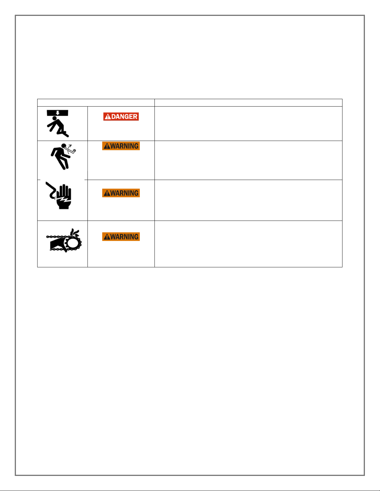
Table 1.1 - Potential Hazards and Preventative Measures
Potential Hazard
Preventative Measure
Pinned or crushed
by closing door.
•Keep yourself and others clear of opening while door is in
motion.
•Do not allow children to play near or operate door.
•Do not operate if door becomes jammed or broken.
Struck by adjusting
wheel bar while
applying spring
turns.
•Be sure bar is adequate in strength and long enough to allow
installer to apply the necessary torque.
•Make sure bar is fully seated into the adjusting wheel slot
before applying pressure.
•
Use two bars while applying turns to the adjusting wheel.
Electrical shock.
•Make sure electrical operator is properly grounded.
•Turn off source power completely prior to servicing the motor.
•Make sure wires are clear of any moving or potentially moving
parts.
•Avoid pinching wires when installing the motor cover.
Pinched by moving
components.
•Make sure the motor is turned off and unplugged before
working with moving parts such as roller chain and sprockets,
drop-out mechanisms, adjusting wheels, etc.
•Locate the possible pinch-points of the unit (Drive chain, coil
area, bottom bar, etc.) Do not operate the door while
someone is near these areas.
Check the following during installation and before leaving the job site:
a. If the unit has tension springs, be sure the proper amount of tension is applied to the torsion
springs, in order to properly counterbalance the weight of the curtain.
b. Securely fasten the tension adjusting wheel in place with the appropriate hardware provided.
c. Check that the keys and/or cotter pins have been set in place and fit properly at all sprockets or
gears.
d. Check that the setscrews in each sprocket or gear (one over the key and one offset from the key)
have been tightened properly.
e. Check all fasteners holding the unit to the building structures.
f. Check all fasteners used to assemble the components of the unit together.
g. Instruct owner or representative in the proper method of operating the door.

Section 2 – Freight Receiving
ECO# 1914 REVISION# 003ES 10-474 DATE 10/15/2020
Upon delivery, check condition of components for damage.
If damage occurred in transit, the installation should not proceed without authorization.
If the installation proceeds, neither the carrier nor the manufacturer will assume responsibility for
replacing the damaged material.
If the installation is stopped due to damage, do the following:
1. Take pictures of the damage.
2. Do not move material from point of delivery to other premises once the damaged components are
discovered.
3. Do not unpack, if the damage is visible prior to removing packaging, until an inspection is made.
4. If the damage is found while removing contents from packaging, the packaging material must be
saved until inspection is made.
5. Container and packaging should be retained by consignee until inspection is made.
6. Have components inspected by carrier’s representative within 15 days from date of delivery.
7. Consignee must obtain a copy of the Inspection Report.
Returning damaged components:
1. Obtain permission from carrier to return.
2. Route the return shipment via the identical carrier(s) involved in the original shipment.
3. Notify the manufacturer when shipment is returned to manufacture plant.
Verify that all components have arrived. Look for the following:
1. Job construction drawings featuring different views (elevation, section, plan, etc.)
2. (2) Guide assemblies; check for guide weathering if included in order
3. Barrel assembly
4. Curtain assembly with bottom bar attached
5. (2) Bracket assemblies
6. Operator; if not attached to bracket
7. Operator cover; may not be included in order
8. Adjusting wheel; if the barrel assembly contains springs
9. Inertia brake; typically on units with springless barrel assemblies
10. Hood and hood supports; may not be included in order
11. Hardware
12. Misc. items (Reelite, lintel seal, hood baffle, etc.)
13. Verify material/finish/color of components matches what is listed on the job construction drawings
and/or what was ordered.
If the delivery is incomplete:
1. Make note on delivery receipt.
2. Note should be verified by driver’s signature.
3. Notify carrier and manufacturer.

Section 3 – Pre-installation
ECO# 1914 REVISION# 003ES 10-474 DATE 10/15/2020
Read entire instruction manual thoroughly. The manufacturer will not be held responsible for
any charges incurred due to improperly installed components.
a. Only trained door systems technicians should perform installation, maintenance, etc.
b. Each unit comes with an individual item number. If the job contains multiple units, be sure to
locate all the components for each item and separate each.
Do not interchange parts from one door to another.
c. Find the job construction drawings for the unit being installed and check the dimensions of the
opening against those on the drawings. See Figure 3.1 below.
d. If the opening dimensions differ from those on the drawings, do not proceed, check with
distributor/manufacturer to be sure the correct door is being installed.
e. Check the jambs of the opening for plumb. Check the head/lintel and floor for level. If the unit is to
be free standing, for example mounted to tubes, check the floor and ceiling for level and for
adequate mounting areas at the top and bottom.
Note: The floor may not be level if a pitched bottom bar is specified.
Work Area:
a. The key to a smooth installation is a clean and well-prepared work environment. Once the
components have been inspected and the job construction drawings have been reviewed; lay out
the components in the order of installation.
b. The opening for the door should be cleaned and inspected for rough surfaces and construction
debris.
c. Lastly the mounting hardware supplied with the door should correspond with the surface and
construction features of the opening.
d. The basic assembly sequence is as follows: guides, barrel w/ rings or tapped holes, brackets,
motor operator (if applicable), curtain, bellmouth, stoppers, weather stripping, hood, and
operator/adjustor/idler covers.
Figure 3.1 - Opening Dimensions and Designations
JAMB
SILL/FLOOR
LINTEL/HEADER
OPENING
HEIGHT
OPENING WIDTH

Section 5 – Guides
ECO# 1914 REVISION# 003ES 10-474 DATE 10/15/2020
Face of Wall Units (Figures 4.1 - 4.2):
Note: Determine which guide assemblies the unit has from the job construction drawings and
compare to the diagrams below.1
Figure 5.1 - Face of Wall “Z” Guide
WALL ANGLE
INNER ANGLE
OUTER ANGLE
WALL
FASTENER
BRACKET PLATE
ASSEMBLY
FASTENER
GUIDE
GAP
GUIDE
PACKOFF
TOE OF
ANGLE
HEEL OF
ANGLE
DISTANCE BETWEEN GUIDES
OVERALL GUIDE DIMENSION PLUS GUIDE SETBACK
SETBACK
Figure 5.2 – Face of Wall “Z” Guide with Windlock Flat
WALL
FASTENER
ASSEMBLY
FASTENER
WALL ANGLE
INNER ANGLE
OUTER ANGLE
BRACKET PLATE
GUIDE
PACKOFF
GUIDE
GAP
WINDLOCK
FLAT
TOE OF
ANGLE
HEEL OF
ANGLE
DISTANCE BETWEEN GUIDES
OVERALL GUIDE DIMENSION PLUS GUIDE SETBACK
SETBACK
1The guide assembly may differ from the right to left hand side of the unit. In these cases, follow the directions for each particular
guide assembly, as well as the job construction drawings provided with the unit.

Section 5 – Guides
ECO# 1914 REVISION# 003ES 10-474 DATE 10/15/2020
Figure 5.3 – Face of Wall “E” Guide
WALL
FASTENER
WALL ANGLE
INNER ANGLE
BRACKET PLATE
ASSEMBLY
FASTENER
OUTER ANGLE
GUIDE
GAP
GUIDE
PACKOFF
TOE OF
ANGLE
HEEL OF
ANGLE
DISTANCE BETWEEN GUIDES
OVERALL GUIDE DIMENSION
PLUS GUIDE SETBACK
SETBACK
Figure 5.4 – Face of Wall “E” Guide with Windlock Flat
GUIDE
GAP
WALL
FASTENER
WALL ANGLE
ASSEMBLY
FASTENER
INNER ANGLE
OUTER ANGLE
BRACKET PLATE
WINDLOCK
FLAT
TOE OF
ANGLE
HEEL OF
ANGLE
GUIDE
PACKOFF
DISTANCE BETWEEN GUIDES
OVERALL GUIDE DIMENSION
PLUS GUIDE SETBACK
SETBACK

Section 5 – Guides
ECO# 1914 REVISION# 003ES 10-474 DATE 10/15/2020
Figure 5.5 – Face of Wall “Z” Guide (with Formed Stainless Steel1Angles & Brush Seal -
Fire Door)
BRUSH SEAL
WALL ANGLE
WALL FASTENER
ASSEMBLY
FASTENER
INNER ANGLE - SHAPED FOR
BRUSH SEAL ATTACHMENT
OUTER ANGLE
GUIDE
PACKOFF
DISTANCE
BETWEEN
GUIDES
GUIDE
GAP
ONE STEEL WASHER
ON EACH SIDE OF
FIBER WASHER
OVERALL GUIDE DIMENSION PLUS GUIDE SETBACK
1. Remove the bellmouth from the guide by removing the bolts that anchor the bellmouth to the wall
angle. Loosen the first bolt closest to the bellmouth on the guide.
2. Certain guide assemblies may have to be disassembled in order to mark the location of the wall
fastener mounting holes and fasten to the wall. 2
•“Z” guides, with or without windlock flat, may not have to be disassembled to install.
•“E” guides, with or without windlock flat, must be disassembled in order to install the wall
angle.
3. Measure the distance from the opening/jamb to the heel of the wall angle (on “E” guides) or the
toe of the wall angle (on “Z” guides). This distance is referred to as the “Overall Guide Dimension
plus Guide Setback”; see guide assembly Figures 5.1 - 5.5. See the job construction drawings
for the dimensions.
4. Place mark on the floor at measured location. Check the distance between these marks and
compare with the job construction drawing. It will be the “Distance Between Guides” plus the
“Overall Guide Dimension plus Guide Setback” at both jambs.
If the measurement does not equal the dimensions on the job construction drawings, STOP.
Check the guide dimensions against those on the job construction drawings to be sure the correct
guides are being installed. If so, repeat previous step and re-check.
5. Scribe a plumb line on the wall from the marks on the floor.
1Formed stainless steel guide assemblies have the same basic dimensions as structural steel guide assemblies shown.
2In some cases where there is a mounting member, such as a structural tube (not provided by door manufacturer), the guide may
be fastened to the mounting member and then the entire assembly is stood up and installed together. If the guides are too heavy to
stand up assembled, they will have to be installed in pieces.

Section 5 – Guides
ECO# 1914 REVISION# 003ES 10-474 DATE 10/15/2020
6. Place the guide or wall angle against the scribed line, check the top of the guide for level, and
mark the location of the wall fastener mounting holes.
Note: For fire doors, mark the holes at the top of the wall fastener slot to allow for upward
expansion of the guides.
7. If the guide is attached to the wall with fasteners, drill mounting holes for the wall fasteners and
fasten the guides / wall angle with the hardware provided. Check the job construction drawings
for the wall fastener required. Tighten the wall fasteners to the recommended installation torque
in Torque Specification Tables in Section 14.
8. If the guide is attached to the wall by welding to structural steel, see the job construction drawings
for details on weld location, type, pitch, size, etc.1
9. Reassemble inner and outer angles if necessary.
10. Adjust the guide gap if necessary. Guide gap is critical and must be verified. Check the job
construction drawing to determine what guide gap is required for the unit.
11. Preload the assembly fasteners per the torque recommendations in the Torque Specification
Tables in Section 14.
12. If guide brush seal is provided, fasten it to the guide at this time per the guide detail on the job
construction drawings.
Between Jambs (Four Angle Guide) (Figures 5.6-5.8):
Note: Determine which guide assemblies the unit has from the job construction drawings and
compare to the diagrams below.2
Figure 5.6 – Between Jambs Four-Angle Guide
WALL
FASTENER
WALL ANGLE
ASSEMBLY FASTENERS -
FIRE DOORS HAVE ONE
STEEL WASHER ON EACH
SIDE OF FIBER WASHER
INTERMEDIATE
ANGLE
INNER ANGLE
OUTER ANGLE
BRACKET PLATE
GUIDE
PACKOFF
GUIDE
GAP
OVERALL GUIDE DIMENSION
DISTANCE
BETWEEN
GUIDES
1Minimum recommended weld rod: AWS A5.1, Grade E-70.
2The guide assembly may differ from the right to left hand side of the unit. In these cases, follow the directions for each particular
guide assembly, as well as the job construction drawings provided with the unit.

Section 5 – Guides
ECO# 1914 REVISION# 003ES 10-474 DATE 10/15/2020
Figure 5.7 – Between Jambs Four-Angle Guide with Windlock Flat (Shown with
fascia mounting channel provided for mounting fascia.)
BRACKET PLATE
WALL FASTENER
INTERMEDIATE
ANGLE
ASSEMBLY
FASTENER
INNER ANGLE
OUTER ANGLE
GUIDE
PACKOFF
GUIDE
GAP
WINDLOCK
FLAT
OVERALL GUIDE DIMENSION
DISTANCE
BETWEEN
GUIDES
FASCIA MOUNTING CHANNEL
1. Remove the bellmouth from the guide by removing the bolts that anchor the bellmouth to the wall
angle. Loosen the first bolt closest to the bellmouth on the guide.
2. Certain guide assemblies may have to be disassembled in order to mark the location of the wall
fastener mounting holes and fasten to the wall. The four angle guide assembly may be too heavy
or to compact to allow the proper tool to be used in order to apply the necessary torque to install
the guide. 1
3. Measure the “Opening Width” or distance between jambs at the top and bottom of the jambs and
compare with the job construction drawings provided. If this distance is not equal to the job
construction drawing dimension, do not proceed!! Be sure the correct unit is being installed.
Contact the project manager.
4. Determine where the fascia of the door
will be located with respect to the header
/ lintel (if one exists) and the jamb.
5. If a header/lintel exists, see the elevation
view of the job construction drawings to
determine if the door is to be placed
against the header as shown below. If
so, project a plumb line from the header
to the floor. Mark the floor at this
location.
6. If a header/lintel does not exist, or if the
door is not going to be placed against
the header/lintel, contact the project
manager to determine where the door
Figure 5.8 - Locating and Marking a B.J. Four
Angle Guide Assembly
FASCIA MOUNTING
CHANNEL
HEADER / LINTEL
LINE ABOVE
MARK THE FLOOR
TO LOCATE THIS
LEG OF WALL ANGLE
1In some instances where there is a mounting member, such as a structural tube (not provided by door manufacturer), the guide
may be fastened to the mounting member and then the entire assembly is stood up and mounted in place together. If the guides are
too heavy to stand up fully assembled, the guides will have to be disassembled to be installed.

Section 5 – Guides
ECO# 1914 REVISION# 003ES 10-474 DATE 10/15/2020
will be located. Mark the floor at this
location and scribe a plumb line up the
jambs.
7. Stand the guide/wall angle up to the wall, holding the bottom of the guide on the mark while
making the guide plumb. Mark the location of the wall fastener mounting holes.
Note:For fire doors, mark the holes at the top of the wall fastener slot to allow for upward
expansion of the guides.
8. If possible, check the “Distance between Guides” 1dimension at this time.
If the “Distance between Guides” dimension does not equal the dimension on the job
construction drawings, STOP. Check the guide dimensions against those on the job construction
drawings to be sure the correct guide is being installed. If so, repeat the previous steps and check
the “Distance Between Guides” dimension again.
9. If the guide is attached to the wall with fasteners, drill mounting holes for the wall fasteners and
fasten the guides / wall angle with the hardware provided. Check the job construction drawings
for the wall fastener required. Tighten the wall fasteners to the recommended installation torque
in the Torque Specifications tables in Section 14.
10. If the guide is attached to the wall by welding to structural steel, see the job construction drawings
for details on weld location, type, pitch, size, etc.2
11. Reassemble guides if necessary.
12. Adjust the guide gap if necessary.
Guide gap is critical and must be verified. Check the job construction drawing to determine what
guide gap is required for the unit.
13. Preload the assembly fasteners per the torque recommendations in the Torque Specification
tables in Section 14.3
1The “Distance between Guides” dimension may be taken from the tip of the inner or outer angle, depending on which angle
extends further into the opening. See the job construction drawing of the guide detail.
2Minimum recommended weld rod: AWS A5.1, Grade E-70.
3Fire door guide assembly fasteners require fiber washers to be used with the assembly fastener.

Section 5 – Guides
ECO# 1914 REVISION# 003ES 10-474 DATE 10/15/2020
Between Jambs (Two-Angle Guide with Tube) (Figure 5.9):
Note: Determine which guide assemblies the unit has from the job construction drawings and
compare to the diagrams below.1
Figure 5.9 – Between Jambs Two-Angle Guide Mounting to Tubes2)
INNER ANGLE
OUTER ANGLE
ASSEMBLY
FASTENER
TUBE
SADDLE
SADDLE FASTENER
TO FLOOR
BRACKET PLATE
GUIDE
GAP
GUIDE
PACKOFF
OVERALL GUIDE DIMENSION
DISTANCE
BETWEEN
GUIDES
ONE STEEL WASHER
ON EACH SIDE OF
FIBER WASHER
CLIP ANGLE FOR
BRACKET MOUNTING
1. Measure the “Opening Width”, the distance between jambs. Compare with the job construction
drawings provided.
If this distance is not equal to the job construction drawing dimension, do not proceed!! Be sure
the correct unit is being installed. Contact the project manager.
2. The tubes are usually supplied with the inner and outer guides already attached, and can usually
be installed as one unit. For larger units, installing the tubes with the guides attached may prove
difficult. The tubes may need to be installed without the inner and outer angles attached. If you
feel this is the case, remove the inner and outer angles at this time.
3. Determine where the fascia of the door will be located with respect to the header/lintel (if one
exists) and the jamb.
4. If a header/lintel exists, see the elevation view of the job construction drawings to determine if the
door is to be placed against the header. If so, project a plumb line from the header to the floor.
Mark the floor at this location.
5. If a header/lintel does not exist, or if the door is not going to be placed against the header/lintel,
contact the project manager to determine where the door will be located. Mark the floor at this
location.
1The guide assembly may differ from the right to left hand side of the unit. In these cases, follow the directions for each particular
guide assembly, as well as the job construction drawings provided with the unit.
2If bottom bar locking is provided, the slide bolt from lock may interfere with saddle. Orient saddle or modify saddle so the slide bolt
can move freely without interference.

Section 5 – Guides
ECO# 1914 REVISION# 003ES 10-474 DATE 10/15/2020
6. Locate the Saddles (brackets used to constrain the tube at the bottom). There are two types of
saddles: standard saddles and inverted saddles. Both utilize the same steps for installation. The
difference is the mounting flange. Fire doors come with inverted saddles for mounting at the
bottom of the tube.
Note: If bottom bar locking is provided, be sure to orient the saddles as not to interfere with the
throw of the slide bolt. See Figure 5.11.
Figure 5.10 – Tube Saddles Figure 5.11 – Tube Saddle Hole location
REGULAR SADDLE INVERTED SADDLE
(MOST COMMON)
MARK ON
FLOOR PLUMB
WITH HEADER
MARK HOLES
FOR SADDLE
THROW OF SLIDE BOLT
7. Use the mark placed on the floor in the previous steps, to locate where the saddle will be and
mark the hole locations by placing the saddle on the floor. See Figure 5.11.
8. Double check the width dimensions provided on the job construction drawings, then drill holes for
the saddle fasteners.
9. Install saddles using the provided hardware.
10. Fire door guides mounting to tubes, require the use of a slip joint. There are (3) mounting styles
for slip joints, as detailed in Figures 5.12, 5.13 and 5.14. Refer to the job information to
determine the correct mounting style for the unit. Locate the Slip Joint Mounting Member(s).
11. Use the job information and the marks made in the previous steps to determine the correct Slip
Joint Mounting Member location. Install using the provided hardware. Use only enough
fasteners to hold the Mounting Members securely in place (2), as they will be removed in a later
step.
12. Determine the required tube length. Refer to Figure 5.12, 5.13 or 5.14, depending on which
configuration you are installing.
a. Measure from the “Floor to Slip Joint Mounting Member” as shown in the corresponding
figure below. Record this measurement.
b. To allow for heat expansion, the steel tube will need to be cut short. To determine the
required “Expansion Allowance”, round the measurement taken in the previous step up to the
nearest foot increment. Multiply the rounded value by 1/8 in/ft. Refer to the table below for
examples:
Table 5.1 – Slip Joint Expansion Allowances
Floor to slip
joint mounting
member (ft)
9 10 11 12 13 14 15 16 17 18 19 20
Expansion
Allowance (in) 1 1/8 1 1/4 1 3/8 1 1/2 1 5/8 1 3/4 1 7/8 2 2 1/8 2 1/4 2 3/8 2 1/2

Section 5 – Guides
ECO# 1914 REVISION# 003ES 10-474 DATE 10/15/2020
c. Calculate the Tube Length:
Tube Length = “Floor to Slip Joint Mounting Member” – “Expansion Allowance”
d. Cut the tubes to the calculated “Tube Length”. Make sure you cut the excess tubing from the
top. Otherwise you will cut off necessary mounting holes and/or notches.
Note: If regular saddles are provided, the tube length will have to be adjusted because the tube will
not sit on the saddle flanges instead of the floor. Subtract the thickness of the flanges from the tube
length.
13. Remove the Slip Joint Mounting Member(s). Place the Slip Joint Mounting Members in the tops
of the tubes.
14. Orient the tubes (ensure the guides, mounting holes or notches are facing the correct direction.)
Place the bottom of the tube over the saddle. Stand the tube upright and reattach the slip joint
mounting member using the previously drilled/marked holes to locate. Use all provided fasteners
at this stage. Check that installed tube is plumb.
15. If you removed the inner and outer angles in Step 2, reinstall them at this point.
Figure 5.12 – Slip Joint - Between Floor and Ceiling Mounting Assembly
FASTENERS AT FLOOR
FLOOR (EXISTING)
5 MIN.
EMBEDMENT
FASTENERS
AT CEILING
1/8"/ft. OF HEIGHT
FOR EXPANSION
TUBE LENGTH
(CUT TO LENGTH
INFIELD AS REQ'D)
FLOOR MOUNTING
TUBE SADDLE
FLOOR TO
SLIP JOINT
MOUNTING
MEMBER

Section 5 – Guides
ECO# 1914 REVISION# 003ES 10-474 DATE 10/15/2020
Figure 5.13 – Slip Joint - Floor to Wall with Plate Mounting Assembly
TUBE LENGTH
(CUT TO LENGTH
IN FIELD AS REQ'D)
1/8"/ft. OF HEIGHT
FOR EXPANSION
FASTENERS
AT FLOOR
FLOOR (EXISTING)
5 MIN.
EMBEDMENT
FIRE RATED WALL
(BY OTHERS)
FASTENERS AT WALL
FLOOR MOUNTING
TUBE SADDLE
FLOOR TO
SLIP JOINT
MOUNTING
MEMBER

Section 5 – Guides
ECO# 1914 REVISION# 003ES 10-474 DATE 10/15/2020
Figure 5.14 – Slip Joint - Floor to Wall with Angle Mounting Assembly
FASTENERS AT FLOOR
(SEE SHOP SHEET)
FLOOR (EXISTING)
1/8"/ft. OF HEIGHT
FOR EXPANSION
5 MIN.
EMBEDMENT
FIRE RATED WALL
(BY OTHERS)
TUBE LENGTH
(CUT TO LENGTH
IN FIELD AS REQ'D)
REF. FASTENERS AT WALL
(SEE SHOP SHEET)
FLOOR MOUNTING
TUBE SADDLE
FLOOR TO
SLIP JOINT
MOUNTING
MEMBER
•Mixed Guides (One Face of Wall and One Between Jambs):
1. Refer to the job construction drawings for specific mounting information.
2. Follow the steps in the preceding sections for each of the respective guide configurations.
3. Ensure that the guide centers (centerline of the guide openings) are aligned before proceeding

Section 6 – Barrel and Brackets
ECO# 1914 REVISION# 003ES 10-474 DATE 10/15/2020
Note: Check to see if a hood support will be required. If so, refer to the “Hood Support
Installation” section before proceeding to the barrel and brackets.
1. Refer to the job construction drawings to determine the “coil side” of the opening, or the side of
the opening on which the coil is to be installed. Then determine which jamb wall is your “operator
side”, or side on which the operator is to be installed. The following instructions refer to these
directional cues.
Note: Units without operators (such as push-up units) are still considered to have an “operator”
side. The shaft and job drawings will be marked with “operator” side regardless of the operation
of the door so that it can be used as a directional cue.
2. Unpack the barrel assembly. Note the markings on the barrel, see Figure 6.1 below.
Figure 6.1 – Barrel Markings – left hand adjust shown
OPERATOR
L.H. ADJUST
# OF TURNS OPENED / CLOSED
LIFT POINT
JOB NUMBER
3. Position the barrel assembly on the coil side of the opening, with the end marked “operator”
towards the “operator side” of the opening. In order to alleviate the ring and bracket installation,
place the barrel assembly on blocks or spacers such that it is elevated off the ground.
Note:Choose sufficiently sized blocks. The barrel assembly should be elevated off the ground
enough that the brackets can be installed without contacting the floor.
4. Check to make sure the required number of turns is noted on the barrel, as shown in Figure 6.1.
Consult the distributor or the manufacturer if you cannot locate this information. Check that these
numbers match the information provided on the job information. Take note of these numbers, as
access to this information may be obstructed once the curtain is installed.
5. Typically the adjusting wheel is not shipped attached to the barrel. However, if the adjusting
wheel is attached to the barrel, remove by loosening the bolt or set screws that secure the
adjusting wheel to the barrel and sliding the wheel off the inner shaft. See Figure 6.2.
Figure 6.2 – Removal of adjustor from barrel assembly

Section 6 – Barrel and Brackets
ECO# 1914 REVISION# 003ES 10-474 DATE 10/15/2020
6. Refer to the job information provided with the door to determine the correct ring type and quantity.
If the unit does not require rings, skip to Step 9. Many larger diameter (8”, 10”, 12”, etc.) barrel
assemblies do not require rings for curtain attachment.
7. Locate the rings in the hardware bag/box provided. Check that you were supplied the correct
type and quantity. (Use Figure 6.3as a visual aid.)
8. Use the information in Figure 6.3to install the rings.
Note: It is critical that the rings are installed correctly in relation to the coiling direction, or the
direction of wrap as the door travel upward. The rings act as graduated spacers, meaning they
increase in diameter such that the curtain wraps in a consistent and smooth manner. Use the arrows
on the figures below to determine the correct orientation of the rings in relation to the coiling direction.
Figure 6.3 – Ring Installation
SP0003 (for 4” barrels) and SP0006 (for 6” barrels) Stamped Rings, and SP0273 Cast
Rings:
SP0003 OR SP0006
3/8 X 1/2 HEX HEAD
WITH NYLON PATCH,
TAPPED INTO BARREL
3/8 LOCK WASHER
UPWARD WRAP
DIRECTION
SP0273
3/8 X 1/2 HEX HEAD
WITH NYLON PATCH,
TAPPED INTO BARREL
3/8 LOCK
WASHER
UPWARD WRAP
DIRECTION
Installation:
•Slip the rings over the barrel, noting direction of wrap, and place over tapped hole in barrel. Insert
the 3/8” x ½” hex bolt (with nylon patch on threads) through the ring into the tapped hole in barrel.
•Be sure rings sit straight on barrel and tighten the fasteners to minimum 20 ft lbs of torque.
SP0251 Cast Rings: (see next page)

Section 6 – Barrel and Brackets
ECO# 1914 REVISION# 003ES 10-474 DATE 10/15/2020
SP0251
3/8 SQ
NUT
3/8 X 1 1/4
HEX HEAD
LOCATE THE NUB, ON THE
INNER PART OF THE RING, IN
THE 7/16" DIAMETER HOLE
PROVIDED IN THE BARREL
UPWARD WRAP
DIRECTION
NUB
Installation:
•Use a small pry bar or large standard screwdriver to spread the gap in the ring by prying between
bolt flange and the nut cradle of the casting (see above).
•Slide the ring over the barrel, noting direction of wrap, and rotate the ring so the locating nub in the
casting aligns with the locating hole in the barrel.
•Insert the 3/8 square nut into the nut cradle of the casting and the 3/8” x 1-1/4” hex bolt through the
bolt flange in the casting and tighten to minimum 20 ft lbs of torque.
•Be sure ring sits straight on barrel.
Ring Attachment (Figures 6.3-6.4):
9. Locate the brackets. Determine the “operator” and “adjustor” brackets by referring to Figure 6.4.
The “operator” bracket may vary significantly based on the operation of the door. The “adjustor”
bracket will contain a label with spring adjustment instructions.
10. Remove the adjusting wheel if you haven’t previously it, and slide the adjustor bracket over the
inner shaft of the barrel assembly. The hood clip angles should be facing inwards and the
dropout pawl should be facing outwards. Install the adjusting wheel (see Figure 6.2).
11. The operator bracket is shipped with a temporary plug holding the sprocket(s) and spacer
washers in place on the bracket. Remove the plug and the bag of hardware attached to it, taking
care not to lose the spacer washers positioned between the sprockets. Do not tighten the set
screws in the bearing at this point. You may need to adjust the position when attaching to the
guides.
Note: Push-up units will not have spacer washers.
12. Align the bearing, sprocket(s) and spacer washers as shown below, and slide the assembly over
the gear end until the inside face of the bracket is approximately 3 inches from the edge of the
outer shaft. It is recommended that you install the keys, located in the bag of hardware you
removed with the temporary plug, into each sprocket at this stage. Do not tighten the set screws
at this point.
Note: Do not install the operator until the barrel and bracket assembly is hoisted into position
and securely fastened to the guides. Installing the operator at this stage will cause the assembly
to be lopsided and cumbersome, making it difficult and potentially dangerous to hoist into
position.

Section 6 – Barrel and Brackets
ECO# 1914 REVISION# 003ES 10-474 DATE 10/15/2020
Figure 6.4 – Brackets and Barrel prior to installation (no spring release fire door brackets shown)
RING
ADJUSTOR BRACKET
OPERATOR BRACKET
HOOD CLIP ANGLE
BRACKET BEARING
GEAR END
ADJUSTOR
ADJUSTOR PIN
COTTER PIN
Hoisting and Installing Barrel Assembly
1. The following methods can be used for hoisting them into place:
•Crane Hoisting: Place a sling or lifting agent under the barrel assembly at the “lift point”
provided on the barrel, see Figure 6.1.
•Forklift Hoisting:Space the forks evenly under the “lift point” provided on the barrel, see
Figure 6.1.Ensure that the barrel assembly is positioned close enough to the tips of the
forks that the fastening holes in the bracket can be aligned with those of the guides without
the forks contacting the wall. Secure the barrel assembly to avoid the slipping off the tip of the
forks.
The addition of brackets may offset the balance slightly from when the “lift point” was marked.
Check to make sure the assembly is properly balanced before hoisting.
2. Before hoisting, refer to the hardware sheet and ensure that the proper type and quantity of
fasteners were provided for the bracket installation. Measure the distance between the brackets
and compare that to your wall angles (or between mounting angles if tubes are present). Fire
door brackets are installed on the outside of the wall angles. Readjust the brackets as needed
before hoisting.
3. Center the barrel assembly between the guides, keeping approximately 2 feet of clearance
between the barrel assembly and wall/guides.
4. Raise the barrel assembly up to the approximate bracket mounting level. The brackets should be
clear of the outer and inner guide angles.
Note: Position the brackets in the upright position, with the mounting holes facing the wall, before
moving the assembly towards the wall. It may be difficult to rotate the bracket when in close to the
wall.
5. Slowly maneuver the barrel assembly towards the guide, and align the mounting holes of the
brackets with those of the wall angles (or mounting angles if tubes are present).
6. Insert the specified bolts and snug tighten, see Figure 6.5.
Table of contents
Popular Garage Door Opener manuals by other brands

Genie
Genie Intellicode 1022 owner's manual

Chamberlain
Chamberlain Security+ 2565 owner's manual

Nice
Nice SO2000 Instructions and warnings for installation and use

Craftsman
Craftsman 139.53515SR - I/2HP owner's manual

Chamberlain
Chamberlain LiftMaster Security+ 3265CM-267 owner's manual

Chamberlain
Chamberlain LiftMaster LM3800A instructions