Chase Doors DuraShield User manual

DuraShield Installation Manual
Motorized – Inside Standoff
21/35544-345-008.cnIsrooDesahC
DuraShield Installation Manual RB0375
1egaP
MOTORIZED INSIDE STANDOFF GENERAL MOUNTING DIAGRAM

DuraShield Installation Manual
Motorized – Inside Standoff
Chase Doors Inc. 800-543-4455 3/12
DuraShield Installation Manual RB0375
Page 2

DuraShield Installation Manual
Motorized – Inside Standoff
Chase Doors Inc. 800-543-4455 3/12
DuraShield Installation Manual RB0375
Page 3
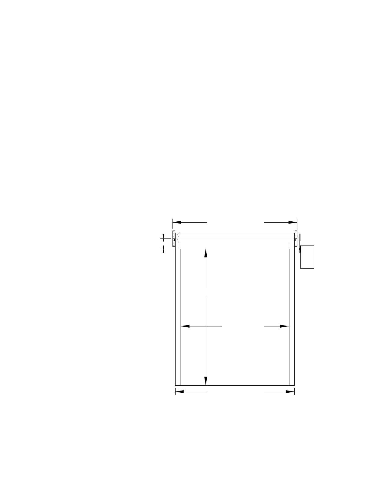
1. Wall preparation – refer to following drawing
Note and understand the clear opening width and height dimensions of the
purchased door before proceeding with the installation.
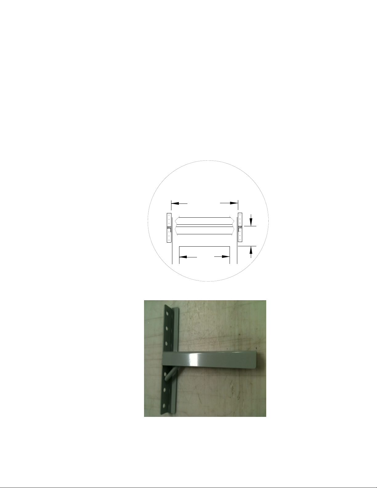
The door must be securely mounted to a smooth surface. If necessary, based on
the wall construction, a metal plate would be installed to the wall as a mounting
surface for the T Brackets (by installer). Typically a 12” x 12” plate would be
needed.
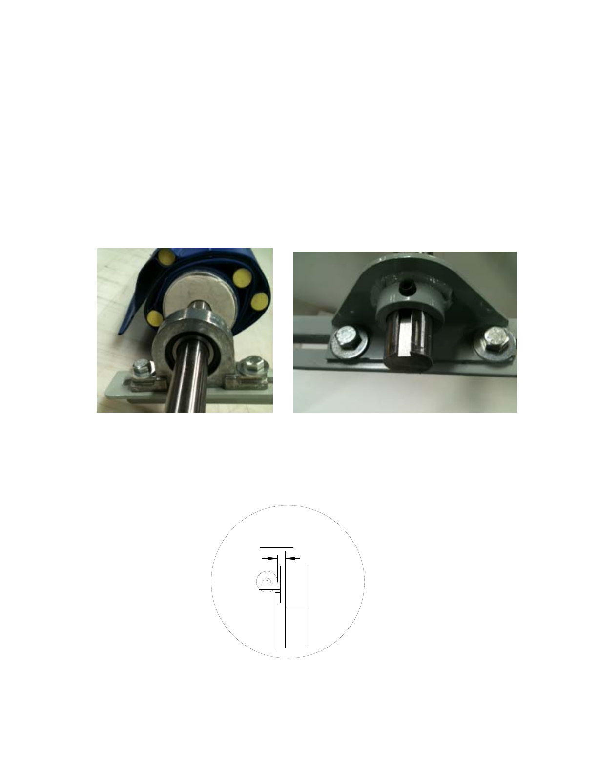
The door, of course, needs to be mounted so that the head and roll are level and
square. The guide tracks must also be square and level in relation to the header,
the wall and each other.
Failure to properly secure, level and square the door components during
installation may result in premature wear and failure of components which will
not be covered by manufacturer warranty.
CLEAR OPENING WIDTH
( FLOOR TO HEADER )
CLEAR OPENING WIDTH PLUS 9"
( OUTSIDE OF TRACKS )
6"
( INSIDE OF TRACKS )
CLEAR OPENING HEIGHT
T BRACKET MOUNTING SURFACE
TO DOOR HEADER DIMENSION
CLEAR OPENING WIDTH PLUS 15"
( OUTSIDE OF T BRACKETS )
Door dimension drawing

DuraShield Installation Manual
Motorized – Inside Standoff
Chase Doors Inc. 800-543-4455 3/12
DuraShield Installation Manual RB0375
Page 4
2. T Bracket Installation
refer to Door Mounting and Dimension Drawings on page 2 & 3
Referring to the door size and following drawing, locate and mount the
T Brackets using appropriate fasteners for the wall surface. The T Bracket bearing
mounting surface should be located to be at minimum 6” above the door header as
shown. The inside mounting dimension of the T Brackets is Clear Opening Width
+ 11 inches, centered on the opening.
6"
T BRACKET MOUNTING
TO DOOR HEADER DIMENSIONS
COW + 11"
COW
Right side shown, Left side opposite

DuraShield Installation Manual
Motorized – Inside Standoff
Chase Doors Inc. 800-543-4455 3/12
DuraShield Installation Manual RB0375
Page 5
3. Roll Installation - NOTE: If you have a Roll Cover with Roll Cover Brackets
provided see section 10 for installation before installing the Roll
Lift the roll into position. On the drive side, locate the pillow block onto the T Bracket
and install the Bearing block to T bracket bolts. On the non drive side, either locate the
pillow block to the T Bracket and install the T Bracket bolts or, for rolls supplied with a
balancing spring, slide the Shaft Retainer Bracket onto the shaft and install the T
Bracket bolts. Align the shaft keyway as shown with the locking allen screw and
tighten the locking screw securely.
Be sure the curtain is coming off the back of the roll.
Standard Pillow Block Bearing Shaft Retainer Bracket used with Balancing Spring
Adjust the roll to wall dimension for both T Brackets as shown below and tighten the Bearing
and Retainer bolts.
1 5/8"
REAR OF CURTAIN ROLL TO
WALL MINIMUM DIMENSION

DuraShield Installation Manual
Motorized – Inside Standoff
Chase Doors Inc. 800-543-4455 3/12
DuraShield Installation Manual RB0375
Page 6
4. Installing the Motorized Operator

DuraShield Installation Manual
Motorized – Inside Standoff
Chase Doors Inc. 800-543-4455 3/12
DuraShield Installation Manual RB0375
Page 7

DuraShield Installation Manual
Motorized – Inside Standoff
Chase Doors Inc. 800-543-4455 3/12
DuraShield Installation Manual RB0375
Page 8
5. For Connection of and Programming of Operator -
refer to instructions provided with the operator
At this time refer to the operator installation manual and make the power and
wiring connections. Refer to your door order to determine the correct voltage for
the supplied operator and for the optional activators that may have been provided
with your door. Adjustment of the Limit switches and Clutch will be done after
installation of the Guide Tracks.

DuraShield Installation Manual
Motorized – Inside Standoff
Chase Doors Inc. 800-543-4455 3/12
DuraShield Installation Manual RB0375
Page 9
6. Installation of Guide Tracks -
refer to Door Mounting and Dimension Drawings on page 2 & 3
Measure the Guide Tracks provided as they may need to be cut on site during
installation. Be sure to cut the bottom of the track if needed. The top of the guide
tracks should be 2 inches minimum to 3 inches maximum from the fully opened
curtain roll.
The Guide Tracks are slotted on one end. This is the top. The rear of the Guide
Track should be flat against the wall surface and are mounted to the wall using
Guide Track L Brackets at top and bottom of the track and using a two foot
spacing between. Tracks are mounted to the floor using two Guide Track L
Brackets if desired.
The slotted tabs on the top of the track are bent outward at an angle. Bend the rear
until it reaches the wall and bend the front to approximately the same angle. Insert
the end of the curtain into the track.
Extended Guide Track Mounting Bracket Top Track Adjustment

DuraShield Installation Manual
Motorized – Inside Standoff
Chase Doors Inc. 800-543-4455 3/12
DuraShield Installation Manual RB0375
Page 10
7. Limit Switch and Clutch adjustment -

DuraShield Installation Manual
Motorized – Inside Standoff
Chase Doors Inc. 800-543-4455 3/12
DuraShield Installation Manual RB0375
Page 11
8. Confirm adjustment of roll clearance in Guide Tracks -
Be sure that both ends of the roll on the T Brackets maintain entry of the curtain
into the Guide Tracks at the curtain positions as shown below and to the minimum
dimension shown on page 4. Fully tighten all roll mounting bolts. It could be
necessary to drill additional holes in the T Brackets to properly adjust the roll to
wall clearance.
CURTAIN
FULLY OPENED
CURTAIN
HALF OPENED
CURTAIN
FULLY CLOSED
RELATIONSHIP OF ROLL TUBE TO GUIDE TRACK ENTRY
9. Installation of Optional Header Brush Seals -
Install the OPTIONAL curtain brush seal by attaching it to the bottom of the external
door as shown. (fasteners not included) It can also mount to another surface as shown.
The installer should determine an appropriate location. Be sure that the brush seal
contacts the curtain when in the full closed position but does not press so hard to
deform the curtain. Install the Top Side Brush Seals, the seals are field fit. Mark holes
in seal mounting strip to mount on the (2) 3/8” L Bracket mounting bolts with
provided fasteners as shown. The brush will contact the curtain and roll.
Brush seal mounted on bottom face of door Top side brush seal and fasteners

DuraShield Installation Manual
Motorized – Inside Standoff
Chase Doors Inc. 800-543-4455 3/12
DuraShield Installation Manual RB0375
Page 12
10. Installation of Optional Roll Cover -
Center the roll cover over the roll. Fasten securely to the wall.
Splice Plate Roll Cover Bracket
If your Roll Cover comes in multiple pieces a Splice Plate is provided, as shown, to connect the
Roll Cover sections together. On wider Roll Covers, support brackets are provided as shown.
The Roll Cover Brackets should be mounted to the wall to support the weight of the Roll Cover.
They would be installed prior to installing the Roll as in section 3. They should be mounted so
that the Roll Cover will be level when installed. They should be mounted near each end of the
Roll Cover location and then spaced at approximately 24” apart. The Roll Cover is then lifted
onto the installed support brackets and secured to the wall as normal. The Roll Cover does not
attach to the support brackets, just to the wall. Any openings in the end caps, for shafts etc., are
to be done by the installer on site.

DuraShield Installation Manual
Motorized – Inside Standoff
Chase Doors Inc. 800-543-4455 3/12
DuraShield Installation Manual RB0375
Page 13
11. Final Assembly -
Go back and recheck all fasteners on the door assembly for tightness
Cycle the door and confirm correct opening and closing positions
Confirm operation of the door operator
Confirm curtain to guide track clearances per section 8. Be sure that guide tracks
are clean and grease free inside and out.
Install Black Vinyl side panels (if supplied). These panels close in the gap
between the Guide Track and the wall, see diagram on page 1. The side panel
attaches to the Guide Track with installed Velcro and the installer attaches it to
the wall in an appropriate manner.
Make sure end user is familiar with operation and has all manuals

DuraShield Installation Manual
Motorized – Inside Standoff
Chase Doors Inc. 800-543-4455 3/12
DuraShield Installation Manual RB0375
Page 14
Popular Garage Door Opener manuals by other brands

Etdoor
Etdoor ET-600E Installation instructions and user guide

Chamberlain
Chamberlain HD950WF user guide

Rollerdor
Rollerdor RD77 installation guide

Chamberlain
Chamberlain Power Drive PD428D owner's manual

Chamberlain
Chamberlain Whisper Drive Security+ 459950 owner's manual

Chamberlain
Chamberlain HD520EVG owner's manual

Beninca
Beninca MB24KIT Operating instructions and spare parts catalogue

Roger Technology
Roger Technology BH30 Series user guide

SOMFY
SOMFY Dexxo Series Quick commissioning guide

Chamberlain
Chamberlain 4000 instructions

Merlin
Merlin Merlin WeatherDrive MR555MYQ Installation and operating instructions

Genie
Genie SC 1500 Operation & maintenance manual