3
Welcome
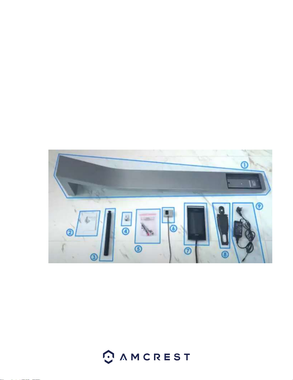
Thank you for purchasing an Amcrest HTR7213-B Thermal Kiosk Solution.
This device is an access control panel that allows entry through the use of facial recognition,
password cards, as well as a non-contact means of applying multi-objective, fast, and effective
temperature readings which can help to lower the risk of illness or disease.
This document provides a quick setup and overview of your Amcrest thermal kiosk solution
installation and setup. For access to a full user manual or further information regarding your device
please visit: http://amcrest.com/support
Note: This device can be used as a standalone device or can be accessed via a local network using
the web user interface on a computer.
Important Safeguards and Warnings
This section of the guide will discuss the proper handling of the device, hazard prevention, and
prevention of property damage. Please read the contents of this guide carefully and comply with
instructions before and after use.
Operation Requirement
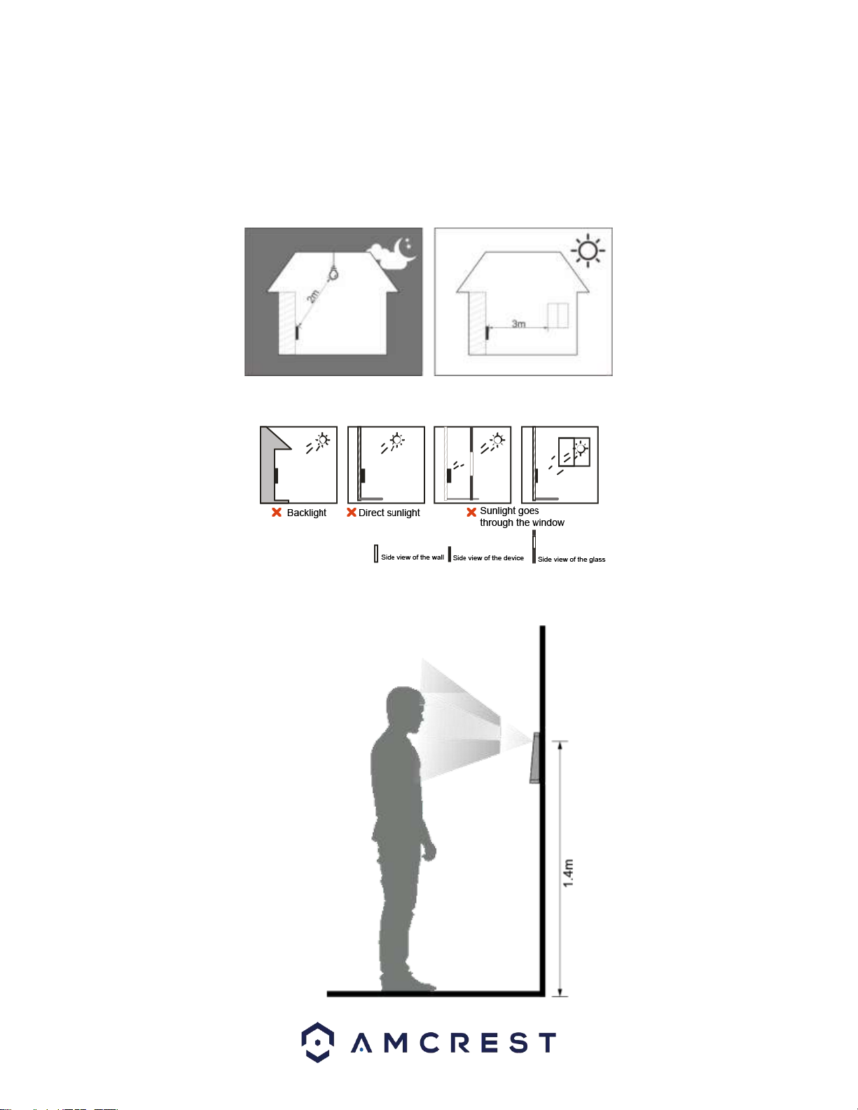
●Do not place or install the device in an area exposed to direct sunlight or near an extreme heat
source.
●Keep the device away from damp areas or in areas prone to high levels of dust or soot.
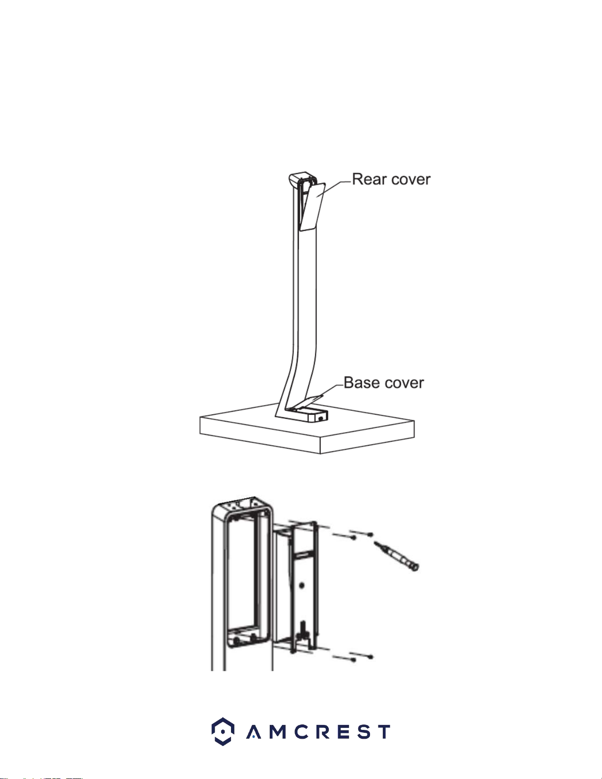
●When installing the device, ensure it is installed horizontally on a stable surface to prevent it from
falling or being damaged.
●Do not drop or splash liquid on the device. Please keep all objects filled with liquid away from the
device to prevent damage to the unit.
●Ensure the device is installed in a well-ventilated area. Do not block any vents on the device.
●Only use the device within the rated range of power. The rated input power range is DC12V, 2.0A.
●Do not attempt to disassemble or repair the device.
●Do not transport, use, or store the device in environments that exceed the recommended humidity or
temperature conditions of 14°F ~ 131°F (-10°C ~ 55°C) with a humidity of 0%RH ~ 90%RH.
●While installing the device, install the temperature monitoring unit in a windless, indoor environment
with an ambient temperature of 59°F to 89.6°F (15°C to 32°C).
●Based on the algorithm compensates and adjustment technology, ensures that the temperature
measurement data of each scan is kept within the range of 0.9°F (0.5°C).
●Allow the device 20 minutes to power on when initially turning on the unit. This will allow the device
to reach thermal equilibrium.
Electrical Safety
●Use the recommended power cables and conform to the recommended rated power specification.
●The power source shall conform to the requirement of the Safety Extra Low Voltage (SELV)
standard, and supply power with rated voltage which conforms to the Limited Power Source
requirement according to IEC60950-1. Please note, the power supply requirement should be found
on the device label.
●Connect the device (I-type structure) to the power socket with the proper protective grounding.
●The appliance coupler is a disconnection device. Keep the coupler accessible for easy
disconnection.