INSTRUCTION MANUAL
& PARTS BREAKDOWN
AME INTERNATIONAL - 2 - WWW.AMEINTL.NET
AME INTERNATIONAL 2 WWW.AMEINTL.NET
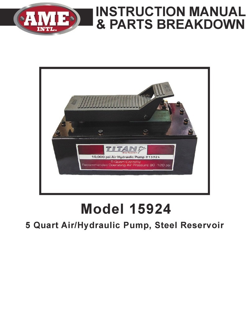
15924 IN STR UCTION MA NUAL & PART LIST
5QT. AIR PUM P W/ STEEL RESER VO I R
SPECIFICATION
DESCRIPTION
tools. It consists of an in-line air and hydraulic cylinder. The ratio of
100:1. In other words, 100 PSI out of every 1 PSI in – 100 PSI input
air pressure equals 10,000 PSI output pressure.
Depressing the RELEASE pedal causes a decrease in pressure and
BEFORE USE
To prevent oil leak during shipment, a metal knob is installed
and tightened to ensure the best sealing function. Loosen it
counterclockwise befo re use.
Note: Alwayssecure threadedport connectionswith non-hardeningpipe thread
compound.Tightensecurelyto preventaccidentalremovalof componentswhilein
chart on above for details of oil port thread size, usable oil capacity, and more.
OPERATION
Operation of the unit is as follows:
1. Connect the hose of the Air/Hydraulic Pump to the hydraulic
coupling on the selected tool.
2. Connect the air supply line to the Air/Hydraulic Pimp. Air
supply should be 5-10 CFM at 100 PSI to obtain proper operating
characteristics. In addition, the air line should be equipped with an
3. Stepping on the PUMP end of the pedal engager the pump,
producing the fo rce necessary to run the tool.
4.
Depressing the RELEASEend of the pump pedal will release the
Input Air
Pressure
(psi)
90-140
Input Port
Threads
¼-18 NPT
Output Port
Threads
3/8-18 NPT
Oil Delivery
(cu.in./min)
0 psi/10,000 psi
24.4/7.3
Internal
Relief
Setting (Psi)
10,000
Usable Oil
Capacity
(cu.in.)
140
Weight
(lbs. w/fluid
19
L+W+H
12.3”x6.7”x7.5”
This Air/Hydraulic Pump supplies hydraulic uid pressure to selected tools.
It consists of an in-line air and hydraulic cylinder. The ratio of hydraulic
uid pressure generated compared to supply air pressure is 100:1. In other
words, 100 PSI out of every 1 PSI in - 100 PSI input air pressure equals
10,000 PSI output pressure.
Depressing the RELEASE pedal causes a decrease in pressure and
pressing the PUMP end of the pedal provides uid pressure.
To prevent oil leak during shipment, a metal knob is installed and tightened
to ensure the best sealing function. Loosen it counterclockwise before use.
Note: Always secure threaded port connections with non-hardening pipe
thread compound. Tighten securely to prevent accidental removal of
components while in use. Take care not to introduce compound into port
orices. Familiarize yourself with the specications and illustrations in this
operator’s manual. Know your pump, its limitations and how it operates
before attempting to use. Refer to specication chart above for details of
oil port thread size, usable oil capacity, and more.
Operation of unit is as follows:
1. Connect the hose of the Air/Hydraulic Pump to the hydraulic coupling
on the selected tool.
2. Connect the air supply line to the Air/Hydraulic Pump. Air supply should
be 5-10 CFM at the 100 PSI to obtain proper operating characteristics.
In addition, the air line should be equipped with an air line lter.
3. Stepping on the PUMP end of the pedal engages the pump, producing
force necessary to run the tool.
4. Depressing the RELEASE end of the pump pedal will release the
pressure.


