Acromet 3000 Series User manual
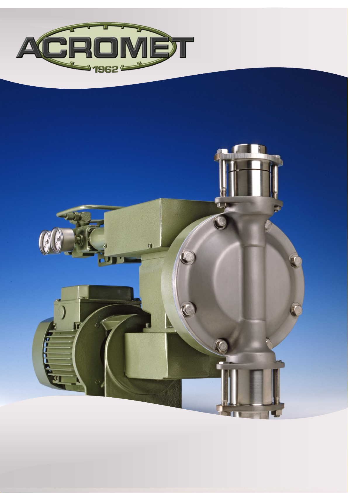
3000 SERIES
DIAPHRAGM METERING PUMP
Precise metering begins with precise design
MP3000PR 001 to 010 Plunger Pump Updated June 2012
Series 3000PR Plunger Pump
Precise metering begins with precise design
Choosing the right metering pump may seem like a straight forward
decision.....but in industry today there are often pumps that are either
under-specified, so the job is not being performed efficiently,
inadequate for the duty.....or over-specified. You need to be looking for
the right pump at the right price by making sure you are specifying the
right pump for the job. We supply Australia’s only manufactured range
of metering pumps to suit the right application to a remarkable range
of industries.
For more than 45 years there has been one name synonymous with quality, accuracy and
reliability in metering pumps.....and this is Acromet.
Laboratory Accuracy, Industrial Reliability
Proudly manufactured in
Australia, every piece of Acromet
equipment is the product of
leading edge technology in
design and manufacture. Our
commitment to our own in-house
R & D, our patented designs, plus
our precision manufacturing, has
built the Acromet reputation for
laboratory accuracy and
industrial reliability. From the
very first stages of design and
specification, right through to the
delivery of each finished product,
and our after sales service,
Acromet quality is never
compromised.
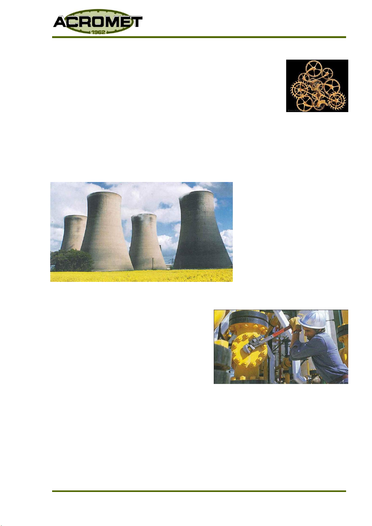
Heavy duty credentials
You will find the Acromet name working in some
of the toughest industrial applications. From
water treatment.....to oil refineries......to
mining........to petro-chemical installations
wherever an environment demands outstanding performance and equipment durability.
Australian Owned
www.acromet.com.au

MP3000PR 001 to 010 Plunger Pump Updated June 2012
Series 3000PR Plunger Pump

MP3000PR 001 to 010 Plunger Pump Updated June 2012
Series 3000PR Plunger Pump
Contents
1. SAFETY ...................................................................................................................................................1
1.1 General ................................................................................................................................... 1
1.2 Mechanical Precautions.............................................................................................................. 1
1.3 Electrical Precautions ................................................................................................................ 1
2. INTRODUCTION........................................................................................................................................1
3. INSTALLATION.........................................................................................................................................2
3.1 Location................................................................................................................................... 2
4. PIPING.......................................................................................................................................................2
4.1 General ................................................................................................................................... 2
4.2 Suction.................................................................................................................................... 3
4.3 Discharge ................................................................................................................................ 3
4.4 Piping Arrangement .................................................................................................................. 4
5. OPERATION..............................................................................................................................................5
5.1 Before Starting......................................................................................................................... 5
5.2 After Starting ........................................................................................................................... 5
6. CAPACITY ADJUSTMENT .......................................................................................................................5
7. MAINTENANCE.........................................................................................................................................6
7.1 Pre Maintenance Cleaning .......................................................................................................... 6
7.2 Lubrication............................................................................................................................... 6
7.3 Suction & Discharge Valves........................................................................................................ 6
7.4 ‘V’ Packings (Packing Seal Item 5) .............................................................................................. 7
7.5 Capacity Control –Zero Adjustment............................................................................................ 8
8. TROUBLESHOOTING...............................................................................................................................9
9. 3000 SERIES METERING PUMPS.........................................................................................................12
9.1 Drive End –Model 3000PR Series - Section A-A ......................................................................... 12
9.2 Drive End –Model 3000PR 001-000 Series –Section A-A –Parts List .......................................... 13
9.3 Drive End –Model 3000PR 001-000 Series –Section A-A - Parts List cont..................................... 14
9.4 Drive End –Model 3000PR 001-000 Series –Section B-B ............................................................ 15
9.5 Drive End –Model 3000PR 001-000 Series –Section B-B - Parts List............................................ 15
9.6 Solution End Model 3000PR –001-000 Series ............................................................................ 16
9.7 Solution End Model 3000PR –001-000 Series –Parts List......................................................... 17
9.8 Valve Assembly Model 3000 PR 001 - 000 ................................................................................. 18
10. CALIBRATION OF A METERING PUMP................................................................................................19
CALIBRATION CYLINDER –INSTALLATION GUIDE ...................................................................... 20
11. SERIES 500 VALVE INSTRUCTIONS....................................................................................................21
APPENDIX................................................................................................................................................................25
1EQUIPMENT DECONTAMINATION PROCEDURE DOC. No. QAPM-SD-19.0-1 .................................... 26
2EQUIPMENT DECONTAMINATION ADVICE DOC. No. SD-19.0-1 .................................................... 27
Rev:12/2015

MP3000PR 001 to 010 Plunger Pump Updated June 2012
Series 3000PR Plunger Pump


MP3000PR 001 to 010 Plunger PumpUpdated January 2017
Page 1
Series 3000PR
METERING PUMPS
3000PR PLUNGER PUMP SERIES
1. SAFETY
1.1 General
Please read and familiarise yourself with all sections of this and other equipment
manuals before proceeding with installation.
Observe all standard precautions which apply to moving machinery.
Observe all standard precautions which apply to electrical equipment, drives
and controls.
Pay particular attention to special safety 'cautions' and 'notes' in this
manual.
1.2 Mechanical Precautions
Prior to undertaking any mechanical maintenance repair, installation, etc.
SWITCH OFF, and disconnect the power before proceeding.
Personnel must wear the appropriate protective safety attire and remove
loose clothing, jewellery etc.
1.3 Electrical Precautions
Before undertaking work on the electrical controls or drives, disconnect
power and place a notice to advise others of the type of work in process.
Ensure all necessary grounds are in place and solid.
Do not disconnect or disable ground connections
CAUTION Follow all electrical regulations where required by electrical
engineering trades.
2. INTRODUCTION
2.1 Acromet metering pumps are designed and manufactured for long, low
maintenance service life and when properly applied, will give many years of
consistent accurate metering and trouble free operation.
2.2 The following instructions should be read and followed to correctly install and
operate the pump and ensure optimum pump life and performance.
2.3 The Pump specification sheet is enclosed at the end of this manual.

MP3000PR 001 to 010 Plunger PumpUpdated January 2017
Page 2
Series 3000PR
3. INSTALLATION
3.1 Location
3.1.1 It is desirable to locate the pump as close as possible to the supply source
(eg tank) in order to minimise suction losses.
3.1.2 The location should be dry and protected from rain and the possibility of
hosing down, with sufficient free space provided around the pump to
allow access for adjustment and maintenance.
3.1.3 The mounting surface should be even and level. The pump base is
provided with two (2) holes for mounting bolts.
4. PIPING
4.1 General
4.1.1 The pump suction valve is located at the bottom of the pump head and
the discharge valve on top. The pump cannot operate without these
valves and for correct operation, valves must be vertical.
4.1.2 Discharge pressure should be more than 20 kPa greater than suction
pressure to prevent over feeding or syphoning and to maintain metering
accuracy.
NOTE When the difference is less than 20 kPa, a back pressure valve and
pulsation dampener should be installed in the discharge line. The
pulsation dampener should be located between pump and valve,
as close to the pump as possible.
4.1.3 A characteristic of reciprocating pump performance is pulsating flow.
Piping should be sized for flow rates at least 3.5 times greater than
maximum capacity of pumps.
NOTE Small diameter piping will produce unpredictable flow rates and
system pressures.
4.1.4 Piping should be as short and straight as possible and arranged to avoid
loops or pockets where gas may accumulate.
4.1.5 All piping should be separately supported close to the pump to avoid
imposing pipe loads on the pump. When handling high or low
temperature liquids, measures should be taken to prevent distortion of
piping imposing loads on the pump.
4.1.6 All pipe work should be flushed clean of any solids which may be present
in the pipe work (i.e. weldslag, dirt following construction or repair)
before final connection to the pump and start-up.
MP3000PR 001 to 010 Plunger PumpUpdated January 2017
Page 3
Series 3000PR
4.2 Suction
4.2.1 Piping must be air tight.
4.2.2 For ease of maintenance an isolating valve should be located near the
pump inlet.
4.2.3 Solids should be prevented from entering low volume pumps or pumps
used for high accuracy metering. A strainer of 150-200 mesh is
recommended and should be adequately sized to prevent restriction of
flow.
4.2.4 Suction pipe entrance should be at least 75 mm above the bottom of
solution tank to allow settlement of larger solids in the tank.
4.3 Discharge
4.3.1 Should it be necessary to install an isolating valve in the discharge line, a
relief valve must be installed between the pump and isolating valve.
4.3.2 The 3000 Metering Pump, being a positive displacement pump, will be
damaged if operated against a closed or partially open isolating valve.
NOTE The relief valve should be set to operate at the maximum rated pump
discharge pressure or maximum rated system operating pressure,
whichever is lower.
CAUTION When pumping hazardous liquids the relief valve discharge should
be piped back to the supply source. This will avoid spillage should
relief valve operate.
NOTE To ensure correct operation and maximise valve life, a pulsation
dampener should be installed between valve and pump
4.3.3 A pressure gauge with gauge protector should be installed to check if the
pump is not operating at too great a discharge pressure. The gauge
should be provided with a petcock valve for isolation from the system
when not required.
4.3.3 When pumping into a high pressure system, a non return valve should be
installed as a safety precaution at the injection point.

MP3000PR 001 to 010 Plunger PumpUpdated January 2017
Page 4
Series 3000PR
4.4 Piping Arrangement Please note Plunger Pumps must have a flooded
suction to avoid damage by running the unit dry
Should it be necessary to
install an isolating valve in
the discharge line, a relief
valve must be installed in
the line between the pump
and isolating valve.
WRONG
CORRECT
Metering pumps are positive displacement pumps and produce pulsating flow. Consequently there
is considerable line pressure loss and suction piping should be sized to ensure adequate NPSHA. If
piping extends for a considerable distance a suitable break tank or pulsation dampener should be installed near
pump.
the pump.
Avoid pockets or loops in piping where gas may accumulate.
WRONG
CORRECT
Where the pump discharge line connects
with a high pressure line, install a
non return valve as a safety precaution.
The presence of solids in the pumped liquid can cause incorrect
pump valve operation and affect metering accuracy.
If solids are present install a strainer with 150 to 200 mesh
and large mesh surface in order to keep pressure drop as small
as possible and ensure that strainer does not become
quickly clogged.
CORRECT
NOTE The diagrams above are representational and are intended as a guide
only. For specific system design or advice please consult a pump systems
engineer or contact Acromet.

MP3000PR 001 to 010 Plunger PumpUpdated January 2017
Page 5
Series 3000PR
5. OPERATION
5.1 Before Starting
5.1.1 Ensure the pump will be operated within its specification.
5.1.2 Check gearbox oil level. Prior to leaving factory, each pump is filled to
the correct level with the recommended grade of oil (see maintenance
section). Any suggestion of oil loss should be investigated.
5.1.3 Check direction of rotation. Correct direction is clockwise when viewing
pump from top of motor.
5.1.4 Ensure system control or isolating valves in discharge line are open.
5.2 After Starting
5.2.1 Pump will normally prime automatically. However, it may be necessary to
run the pump at maximum capacity to clear air. If this is unsuccessful,
disconnect the discharge pipe work or install a petcock in the discharge
line next to the pump to allow air to escape.
CAUTION If pumped liquid is hazardous do not disconnect discharge pipe
work. Install a petcock in the discharge line next to the pump and
pipe petcock discharge to suction vessel or drain to avoid spillage.
5.2.2 Check that pump is operating correctly against discharge pressure.
5.2.3 Ensure that any problems are noted and appropriate corrective or
preventative action is taken.
6. CAPACITY ADJUSTMENT
6.1 Standard manual capacity adjustment is by means of a micrometer. For multiplex
pumps, each pump head is individually controlled by a micrometer located behind
the respective pump head.
6.2 Adjustment should be made whilst the pump is running, though under certain
conditions adjustment is possible when the pump is stopped. To adjust whilst
stopped, rotate the flexible coupling by hand to unload the micrometer. This can
be sensed by the ease with which adjustment can be made. When unloaded,
adjust to desired setting.
NOTE Ensure power supply is disconnected before removing drive-shaft
guard.
[Type a quote from the
document or the summary of an
interesting point. You can
position the text box anywhere in
the document. Use the Text Box
Tools tab to change the
formatting of the pull quote text
box.]
MP3000PR 001 to 010 Plunger PumpUpdated January 2017
Page 6
Series 3000PR
7. MAINTENANCE
7.1 Pre Maintenance Cleaning
Flush the pump to remove all chemical residue.
Clean the pumps exterior to ensure chemical free surface.
Check that appropriate chemical handling and cleaning standards have been
met.
CAUTION ACROMET (AUST)PTY LTD IS UNABLE TO ACCEPT ANY METERING PUMP RETURNED
FOR MAINTENANCE THAT HAS NOT BEEN SUITABLY CLEANED.
It is an Acromet Quality Assurance policy that all equipment returned for repair or service
be supplied with a completed copy of the 'Equipment Decontamination Advice' form, as
shown on page 42 of this manual.
7.2 Lubrication
7.2.1 Change oil after the first month of operation and at 6 months intervals
thereafter.
The following are recommended grades:
SHELL : OMALA 320
BP : GR-XP-320 ISO
MOBIL : MOBIL GEAR 632
CASTROL : ALPHA SP 320
7.2.2 Correct oil level is the horizontal centre line of the solution head.
7.3 Suction & Discharge Valves
7.3.1 During routine maintenance, valves should be dismantled and checked.
Replace worn balls and valve seats. When pumping clean liquids of
moderate viscosity, valves will give many years of trouble free service.
However, valve life can be reduced in applications where discharge
pressure is high, liquid viscosity low or solids are present.
NOTE Should it be necessary to service the valves, cleanliness is
essential and care should be taken to avoid damaging
components.
Refer to valve drawing at end of manual prior to dismantling.
7.3.2 When reassembling, ensure that all O-Rings, ball checks and ball stops
are in the correct position. Failure to fit ball stops can result in closed
head situation and severe pump damage.
MP3000PR 001 to 010 Plunger PumpUpdated January 2017
Page 7
Series 3000PR
7.4 ‘V’ Packings (Packing Seal Item 5)
Pump maintenance should only be carried out by authorised qualified
personnel with appropriate metering pump and system maintenance
experience.
The suction and discharge lines must be isolated and pipework de-
pressurised and drained of chemicals.
Procedure for replacing packing seals is as follows:
7.4.1 First isolate suction and discharge lines.
7.4.2 Disconnect suction and discharge pipe work from Pumping Head.
CAUTION If liquid is hazardous then all necessary precautions must be taken.
7.4.3 Slacken off Adjustment Cap (Item 9).
7.4.4 Remove Pumping Head securing bolts (Item 20) and gently slide off
pumping head.
7.4.5 Remove Adjustment Cap (Item 9) Follower (Item 8) Glad Spacer (Item 7)
Lantern Ring (Item 6) V-Packings (Item 5) and Necking bush (Item 4).
7.4.6 Discard damaged or worn V-Packing seals and thoroughly was and clean
all parts. Check plunger, gland spacer and necking bush for signs of
excessive wear or scoring. If excessive wear or scoring is evident, then
parts must be replaced.
7.4.7 Re-assemble in reverse order using new V-Packing Set.
NOTE V-Packings must face towards pressure (Product).
7.4.8 Adjust seal pressure via Adjustment Cap (Item 9). Correct adjustment is
critical and care must be taken not to over tighten.
Adjust as Follows:
(i) Rotate Adjustment Cap (Item (9) just sufficient to stop end float of
Packing Seal arrangement. (No pressure on seal).
(ii) Start up pump. Slowly adjust Cap (Item 9) until leakage stops.
NOTE Adjustment should be just sufficient to stop leakage.
(iii) Run pump and check for leakage re-adjust as necessary as seals bed
in.
MP3000PR 001 to 010 Plunger PumpUpdated January 2017
Page 8
Series 3000PR
7.5 Capacity Control –Zero Adjustment
Individual capacity control is provided for each pump head by means of a
micrometer located directly behind the respective pump head.
Should it become necessary to reset the mechanism, the procedure is as follows:
7.5.1 With pump running, screw micrometer mechanism in until piston
movement is just stopped. This can be sensed when resistance to turning
becomes constant. Stop pump. Unfasten both mounting screws and
remove micrometer mechanism
NOTE On some units, oil level will be above micrometer and spillage
will occur on removal. Hence measures should be taken to catch
spillage or tilt pump forward to avoid spillage.
7.5.2 Clamp micrometer anvil in vice and holding the barrel to prevent rotation,
loosen the socket set screw located in rear of barrel. This set screw locks
the barrel to the anvil.
7.5.3 Now, holding the mounting flange to prevent it turning, rotate the barrel
until it reads zero.
7.5.4 Again hold barrel to prevent it rotating and retighten set screw.
7.5.5 Set micrometer at 100% and refit to pump.
CAUTION Should oil spillage have occurred, add oil to correct level
before starting pump.
All major mechanical repairs should be undertaken by Acromet’s specialist
servicing workshop in Melbourne. In most cases a pump can be repaired and
despatched in one day

MP3000PR 001 to 010 Plunger PumpUpdated January 2017
Page 9
Series 3000PR
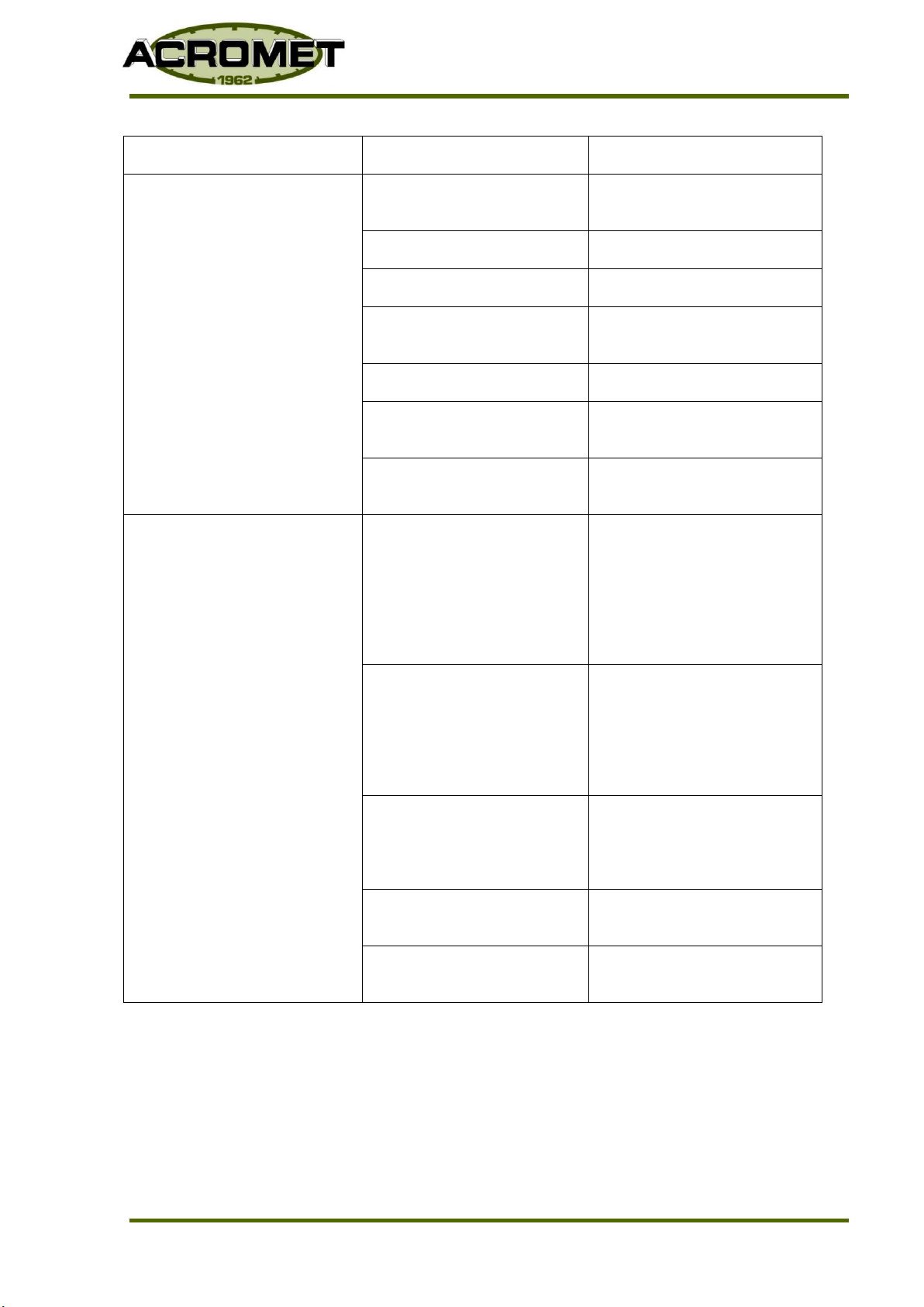
8. TROUBLESHOOTING
Trouble
Cause
Corrections
(A) Pump does not start.
Blown electrical. Fuse.
Check cause and change to
suitable capacity fuse
Electrical overload relay
trips.
Change relay capacity to
correct value.
Electrical wiring breakdown
or defective contact.
Change or reconnect.
Low voltage.
Difference in supply
voltage and rated voltage
of motor.
Find cause and correct.
Defective motor.
Check and replace.
Excessive pressure in
discharge line.
Reduce pressure.
Valve in discharge line
closed.
Open valve
Pump discharge valve
incorrectly reassembled
during maintenance.
Ballstop cushion missing.
Reassemble correctly.
Air in liquid end.
Relieve pressure in
discharge line.
(B) No Flow.
Valve in discharge line
closed.
Open valve.
Pump discharge valve
incorrectly reassembled
during maintenance.
Ballstop cushion missing.
Reassemble correctly.
Overload relay
Reset the switch after
checking the cause and
correcting.
(c) Pump does not work
after operating
normally.
Overload relay
Reset the switch after
checking the cause and
correcting.
Discharge pipe clogged.
Clear the pipe.
Valve in discharge line
closed.
Open valve.
Pump discharge valve
incorrectly reassembled
during maintenance.
Ballstop cushion missing.
Reassemble correctly
MP3000PR 001 to 010 Plunger PumpUpdated January 2017
Page 10
Series 3000PR
Trouble
Cause
Corrections
(D) Reduced pump flow
rate or unstable rate.
Micrometer out of
adjustment
Re Zero.
Valve clogged.
Clean.
Worn valve seat.
Replace seat or valve.
Flow meter incorrect.
Inspect meter, repair or
change.
Leakage from relief valve.
Inspect, repair or change.
Air leaking into suction
piping
Check for leak source and
repair.
Change in pump RPM.
Correct electric power
sources, speed control etc.
(E) Reduced pump flow
rate.
Unstable flow rate.
Flow rate does not
increase as stroke
length is increased.
Cavitation noise may
be apparent.
Insufficient NPSH
available:
(a) Suction pipe
diameter too small.
(b) Suction lift too great.
Enlarge suction pipe, or
install accumulator in the
line close to pump or raise
level of tank.
Raise liquid level.
Viscosity of liquid too
high.
1. Heat or lower viscosity
by other means.
2. Increase suction pipe
diameter.
3. Increase suction
pressure.
Vapour pressure high.
1. Lower liquid
temperature at inlet
port.
2. Raise liquid level.
Suction piping and/or
valve clogged
Clean
Suction strainer clogged
or too small
Clean or replace with larger
unit.

MP3000PR 001 to 010 Plunger PumpUpdated January 2017
Page 11
Series 3000PR
Trouble
Cause
Correction
(F) Excessive pump flow
rate.
Flow continues after
pump has stopped.
Pressure difference across
pump less than 20 KPa
Increase pressure
difference (ie install back
pressure valve).
Discharge line too long or
diameter too small
Reduce length and/or
increase diameter.
Install accumulator in
discharge line.
(G) Liquid leakage from
pump adaptor drain.
Loose or worn V-Packings
Adjust or replace. See
Sec. V-Packings.
(H) Knocking sound in
gearbox.
Excessive discharge
pressure
Check discharge pressure.
(I) Liquid end noise.
Rhythmic noise of pump
valves
Normal
Clogged discharge or
suction valve
Clean valve
(J) Overheating of motor.
Improper voltage
Adjust voltage to motor
specification.
Overload
(Refer to Section K).
Inadequate ventilation
Change motor or relocate
(K) Overload.
Improper Oil
Change
Discharge pressure too
high
Lower to permissible
pressure
Erratic noise of pump
valves
1. Clean valves.
2. Increase pressure
difference (ie install
back pressure valve).
MP3000PR 001 to 010 Plunger PumpUpdated January 2017
Page 12
Series 3000PR
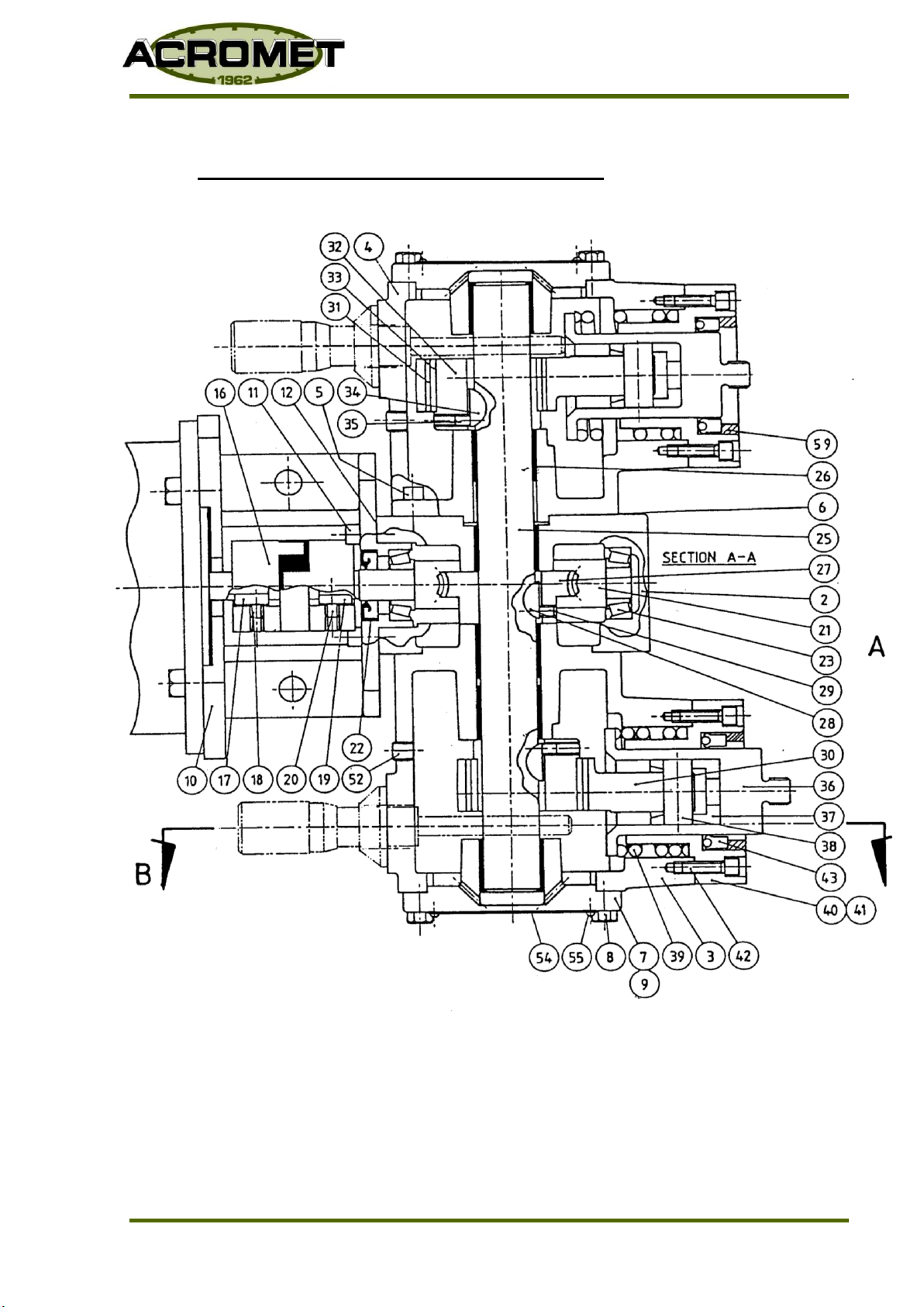
9. 3000 SERIES METERING PUMPS
9.1 Drive End –Model 3000PR Series - Section A-A

MP3000PR 001 to 010 Plunger PumpUpdated January 2017
Page 13
Series 3000PR
9.2 Drive End –Model 3000PR 001-000 Series - Section A-A –Parts List
ITEM
PART NO
DESCRIPTION
SIMP
QTY
DUP
QTY
NOTES
1
8800
Gearbox
1
A
2
8801
Gearbox
1
3
8002
Multiplex Chamber - Simplex
1
1
4
8001
Multiplex Chamber –Duplex
1
5
08-01-14
Screws Multiplex Chamber
4
8
6
8019 *
Gaskets
1
2
7
8003
End Cover
1
2
8
08-02-08
Screws End Cover
4
8
9
8019 *
End Cover Gasket
1
2
10
8802
Motor Spool
1
1
11
08-01-15
Screws Spool
4
4
12
8803 *
Motor Spool Gasket
1
1
16
9130
Coupling
1
1
17
9120
Key, Motor Shaft (supplied with motor)
1
1
18
08-13-01
Screws Motor Shaft Key
1
1
19
9121
Key Coupling (on assembly)
1
1
20
08-01-09
Screw Coupling
1
1
21
2802-
Worm Shaft
1
1
B
22
07-01-01 *
Oil Seal Worm Shaft
1
1
23
06-01-12 *
Bearing Worm Shaft
2
2
24
8804
Main Shaft - Simplex
1
A
25
8006
Main Shaft - Duplex
1
26
06-04-01
bush main Shaft
4
6
27
2021-
Worm Wheel
1
1
B
28
12-01-09
Key Worm Wheel
1
1
29
08-01-09
Screw Worm Wheel Key
1
1
30
8209
Con Rod
1
2
Notes:
A Not Shown
B State Stroking Rate (SPM)
C State Size
* Recommended Spare Parts
MP3000PR 001 to 010 Plunger PumpUpdated January 2017
Page 14
Series 3000PR
9.3 Drive End –Model 3000PR 001-000 Series –Section A-A - Parts List cont.
ITEM
PART NO
DESCRIPTION
SIMP
QTY
DUP
QTY
NOTES
31
8216
Bush Con Rod
1
2
32
8215
Eccentric 0.625”
1
2
C
33
06-05-02
Liner Eccentric
1
2
34
12-01-09
Key Eccentric
1
2
35
08-13-01
Screws Eccentric key
1
2
36
10000
Piston Primary
1
2
37
8026
Cross Head
1
2
38
8024
Pin Wrist
1
2
39
8829
Spring Return
1
2
C
40
8028
Sleeve, Piston
1
2
41
8831
Gasket, Piston Sleeve
1
2
42
08-01-17
Screw Piston Sleeve
2
4
43
07-01-02
Seal Primary Piston
1
2
51
08-12-01
Plug, Drain
2
1
A
52
08-12-02
Plug
1
2
54
9111
Plate, Name
1
2
55
08-10-01
Screw Name Plate
4
8
56
06-04-02
Wrist Pin Bush
1
2
57
09-02-03
Spring Washer, Motor
4
4
A
58
08-08-10
Thumb Screw, Barrel Lock
1
2
A
59
08-01-3
Screw, Adaptor
4
8
A
Notes:
A Not Shown
B State Stroking Rate (SPM)
C State Size
* Recommended Spare Parts
Table of contents
Other Acromet Water Pump manuals


Popular Water Pump manuals by other brands

Speck pumpen
Speck pumpen BADU Spyder I operating instructions

Stenner Pumps
Stenner Pumps SVP4L1 Installation and maintenance manual

CPA
CPA EL 7 IM Programming instructions

SAER Elettropompe
SAER Elettropompe NCB Use and maintenance manual

moyno
moyno 2000 Service manual

KISANKRAFT
KISANKRAFT KK-WPK-20 Operation manual


Varian
Varian Turbo-V 81-M Series instruction manual

GORMAN-RUPP PUMPS
GORMAN-RUPP PUMPS 0 Series Installation, operation, and maintenance manual with parts list

AquaCare
AquaCare BasiTech instruction manual

Senci
Senci SCWP-25 operation instruction

EINHELL
EINHELL GC-DP 3730 Original operating instructions

Levitronix
Levitronix PuraLev 600MU user manual