AMEC FPER Instruction Manual

1“FPER2” and “FPERSR” - Installation and Maintenance manual
1
“FPER” ,“FPER2”
and “FPERSR”
Metering Pumps
1.01
Installation and Maintenance

Attention!
GENERAL SAFETY GUIDELINES
In emergencies the pump should be switched off immediately!
Disconnect the power cable from the power supply!
When using pump with aggressive chemicals observe the regulations concerning the transport and
storage of aggressive fluids!
When installing always observe national regulations!
Manufacturer is not liable for any unauthorized use or misuse of this product that may cause injury,
damage to persons or materials.
Caution!
NORME CE
EC RULES(STANDARD EC)
NORMAS DE LA CE
Direttiva Basso Voltaggio
Low Voltage Directive
Directiva de baja tensión
Direttiva EMC Compatibilità Elettromagnetica
EMC electromagnetic compatibility directive
EMC directiva de compatibilidad electromagnética
Pump must be accessible at all times for both operating and servicing.
Access must not be obstructed in any way!
Feeder should be interlocked with a no-flow protection device.
Pump and accessories must be serviced and repaired by qualified and authorized personnel only!
Always discharge the liquid end before servicing the pump!
Empty and rinse the liquid end before work on a pump which has been used with hazardous or
unknown chemicals!
Always read chemical safety datasheet!
Always wear protective clothing when handling hazardous or unknown chemicals!
2006/95/CE
⎬
2004/108/CE
⎬

3“FPER2” and “FPERSR” - Installation and Maintenance manual
GENERAL INFORMATIONS
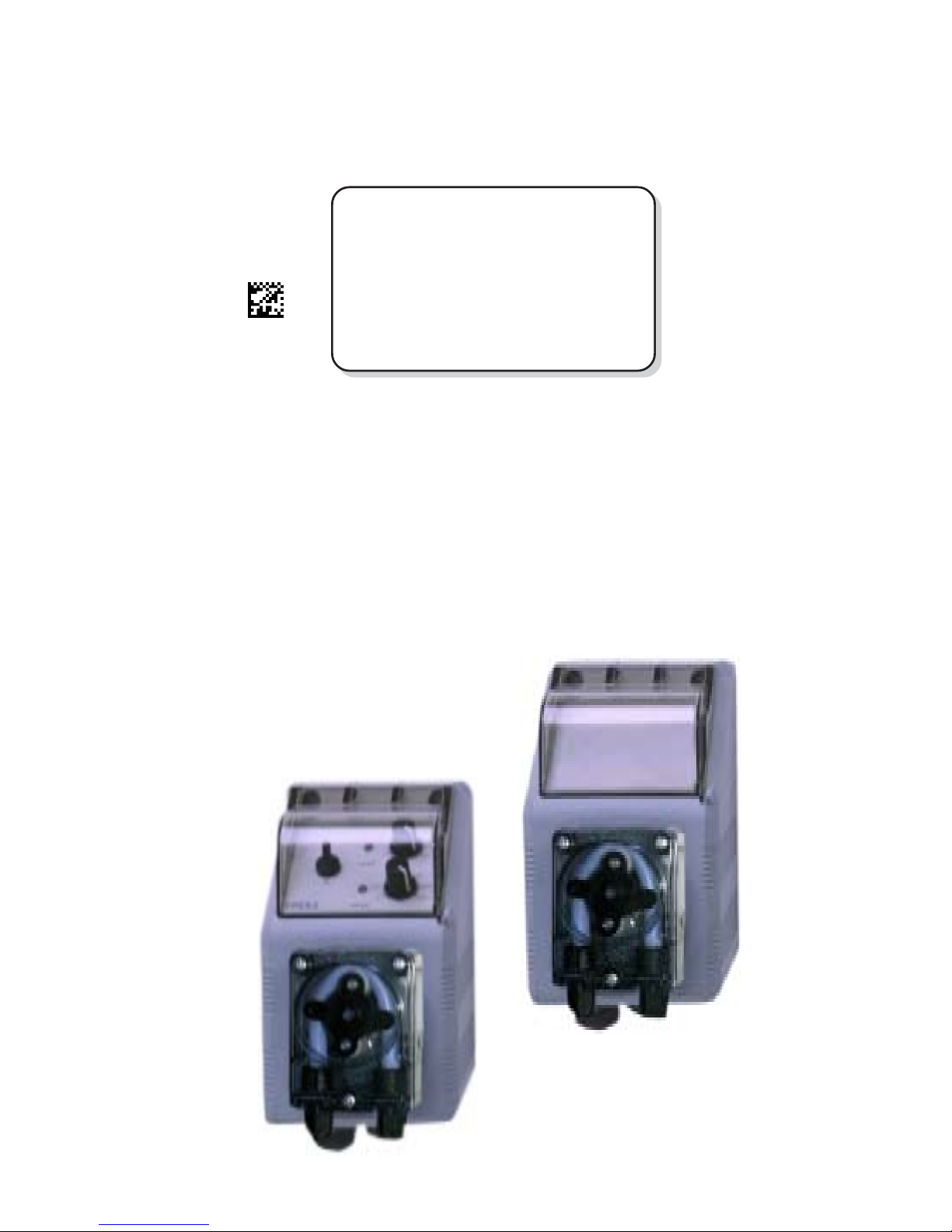
Series “FPER”, “FPER2” AND “FPERSR” peristaltic dosing pumps fits small dosing amounts of liquid
products. They are constituted of the following main assemblies:
Box
Electronic Circuitry
Peristaltic Pump
“FPER” is a peristaltic pump with adjustable electronic time.
“FPER2” is a peristaltic pump with on/off flow adjustment.
“FPERSR” is a peristaltic pump without flow regulation.
Box
Series “FPER2” AND “FPERSR” dosing pumps are assemblied in IP54(PP) plastic material boxes.
Installation is vertical with two screws at a distance of 63mm.
Electronic Circuit
The electronic circuit is made of proven quality.
Peristaltic Pump
2,4 l/h peristaltic pump with 40rpm engine with thermoplastic hose.
INSTALLATION
The pump has all the materials needed for the installation. To start up the series “FPER2” AND
“FPERSR” pump, first mount it on a wall or any other vertical surface. The distance between the
peristaltic engine and the suction filter should not be more then 1.5m. Connect the suction pipe
(transparent one). Be sure the o-ring in the suction valve is in place. Use hands to tight the fitting nut.
Place the suction filter on the bottom of product’s tank. Suction pipe should be as short as possible
in vertical position without any bendes to avoid air bubbles. Install the injection valve and connect it
to the pump head.
To avoid breaking of delivery pipe be sure that it doesn’t touch any other object.
The injection valve should never be installed lower then the product tank to avoid that injection valve
breaking lets the product flow freely into the system. It is reccommended to use an anti-syphon valve
(code 108.136.1) on the delivery side if the only way to install the injection valve is lower then the tank.
This valve prevents vacuum on the pump. Check on a regular basis the delivery valve and immediately
change it when inoperable. Do not install tanks with chemical beneath the pump to avoid the vapors
damaging the pump.
METERING
The series “FPER”, “FPER2” AND “FPERSR” pump features are located in a label on the pump
box. They include: power supply, working counterpressure (Kpa/bar) and pump capacity in
liter per hour (l/h). All the dosing information is withwith water at a 20 °C temperature, at the
maximum counterpressure reported in the label, using the injection valve and the % knob set to
the maximum. Dosing accuracy is ± 2% l/h at constant maximum counterpressure and 1 cps
flow (max viscosity : 60 cps).Warning: Counterpressure changes or viscosity changes at the
same stroke number may change the single stroke injection quantity. Check capacity charts for
further informations.

4“FPER2” and “FPERSR” - Installation and Maintenance manual
ELECTRICAL CONNECTIONS
Electrical plug provided is “SCHUKO”. Proceed with followings before make the electrical connections:
- check and verify ground system;
- install a 0.03 A breaker to prevent current peeks due to ground system
malfunctions;
- Check and ensure supplied power is as requested in the pump label;
- connect ground before proceeding with others electrical connections;
Electrical features:
Power supply range for 230 V models 198÷242 VAC
Frequency 50÷ 60 Hz; Average input power at max speed: 5W
Do not connect the pump in parallel to an inductance load, like motors, to prevent
electronic circuitry damages. Always usa a connector to cut off spikes due to other
devices switching.
Dosing pump in parallel connection with inductive loads
P - Metering Pump
R - Relay
I - Connector or Multi-Pole Safety Devide
E - Inductance Load
A - Power Supply
ELECTRICAL PROTECTION
“FPER2” circuit is protected with a fuse located beneath the back cover of the pump. Proceed as
follows to replace the fuse:
- Unplug power supply
- remove the 8 screws on the back cover of the pump
- replace fuse, use only approved fuses reported in table below
- put back cover in place, take care of seal position
Pumps are equipped with a protection against overvoltages (working voltages: 275 V), and a
voltage peek protection up to 4 KV, 50 μsec against pulses like in figure

5“FPER2” and “FPERSR” - Installation and Maintenance manual
HYDRAULIC CONNECTIONS
Use piping provided in the shipping pack to make connections:
Suction hose Delivery hose
4x6 mm PVC 4x6 mm PVC
(transparent) (transparent)
- Temperature range: -10 ÷ 60°C
- Minimum pipe degree of bending should be within 8/12 external diamters of the pipe.
MAINTENANCE
Before proceed with maintenance or service of the pump:
- wear the used chemical’s safety data sheet suggested protections (glasses,
gloves,etc )
- unplug power supply
- unload delivery pipe and vent it to ATM pressure
- unload suction pipe.and vent it to ATM pressure
To avoid damages and injuries flows the pump head with fresh water. For repair shipping pls bridge
the suction valve and the delivery valve with a pipe.
Follow chemical safety data sheet (provided by the chemical manifacturer) when
entering in direct contact with it.
“FPER”, “FPER2” AND “FPERSR” type pump need small maintenance: clear once per year all the
valves and the foot filter. If high chrystallizing products are used perform maintenance once per
month and after long non operation times cleaning all the valves and the foot valve. To remove
chrystal depositions follow below procedure:
- unscrew the injection valve connection and dip delivery pipe and foot valve in water;
- prime the pump with water and let the pump work with water for 5 min;
- replace water with a chrystal solvent product and let the pump work with it for 10 min;
- let the pump work with water again for 5 min;
- put back in place injection valve connection and prime the pump.
It’s important to tight the pipe blocking nuts to avoid chemical product leaks that can damage the
pump. If it happens tight the pipe blocking nuts and rinse the pump with fresh water.
To avoid any damage, please change pump’s hose every 500 working-hours.

6“FPER2” and “FPERSR” - Installation and Maintenance manual
TECHNICAL FEATURES
Max suction pipe lenght 1,5 meters
Environment temperature: 0 ÷ 45°C (32 ÷ 113°F)
Chemical Temperature: 0 ÷ 50°C (32 ÷ 122°F)
CONSTRUCTION MATERIALS
Case: PP
Valve Balls: GLASS, PTFE (upon demand)
Suction pipe: PVC
Delivery pipe: PVC
Valve body : PP/PVDF (upon demand)
Injection valve: PP V-706 (glass ball, HASTELLOY C276 spring).
Foot Filter: PP/PVDF (upon demand)
PROVIDED ACCESSORIES
n.2 Dibbles ø6
n.2 Screws 4,5 x 40
n.1 Fuse 5 X 20 delaied
n.1 Foot filter/valve assy
n.1 Injection valve
m 4 PVC suction and delivery hose
n.1 Instruction manual

7“FPER2” and “FPERSR” - Installation and Maintenance manual
“FPER” , “FPER2” Series Description
Turn On / Off Switch
Status Led
Pause Time
Adjustment Knob
Dosing Time
Adjustment Knob
Turn On / Off Switch
Status Led
Dosing Activity
Switch
Dosing Time
Adjustment Knob

MAURIZIO MANCINI, Presidente EMEC S.r.l.
Via Donatori di sangue, 1 - 02100 Rieti - Italy
Tel. +39 0746 2284 1 - Tel. +39 0746 1725114 - Fax +39 0746 2284 2 -
DECLARATION OF CONFORMITY
The Company EMEC s.r.l.
Company Address Via Donatori di Sangue 1 - 02100 RIETI - ITALIA
DECLARES
under its own responsibility, that the product
Description: Diaphragm metering pump, series Fxx
Serial no.: refer to the nameplate on the device
complies to the following standards:
EC RULES (STANDARD EC)
Low Voltage Directive (2006/95/CE)
EMC electromagnetic compatibility directive (2006/42/CE)
EUROPEAN HARMONIZED STANDARDS UNDER DIRECTIVE
EN 12100-1, EN 12100-2, Safety of Machinery
EN 809, Pumps and pumping units for liquids-Safety requirements
UNI 10637, Measuring instruments for temperature, pH, ORP, free and
combined chlorine and the isocyanuric acid are within the requirements of
standard UNI 10637.
D.M. 7 February 2012 n.25 – D.M. 6 April 2004 n. 174 – Regulation EU
10/2011- Equipment intended to come into contact with food.
The product passed the final test.
Date: 14/06/2012
Signature

MAURIZIO MANCINI, Presidente EMEC S.r.l.
Via Donatori di sangue, 1 - 02100 Rieti - Italy
Tel. +39 0746 2284 1 - Tel. +39 0746 1725114 - Fax +39 0746 2284 2 -
DICHIARAZIONE DI CONFORMITà
La società EMEC s.r.l.
con indirizzo Via Donatori di Sangue 1 - 02100 RIETI - ITALIA
DICHIARA
sotto la propria responsabilità, che il prodotto
Descrizione: pompa dosatrice a membrana, serie Fxx
Seriale n.: fare riferimento all’etichetta riportata sul prodotto
è conforme alle seguenti norme:
NORME CE
Direttiva Basso Voltaggio (2006/95/CE)
Direttiva EMC Compatibilità Elettromagnetica (2006/42/CE)
NORME ARMONIZZATE EUROPEE NELL’AMBITO DELLA DIRETTIVA
EN 12100-1, EN 12100-2, Sicurezza sul macchinario
EN 809, Pompe e gruppi di pompaggio per liquidi - Requisiti di sicurezza
UNI 10637, Gli strumenti di misura per la temperatura, il pH, il potenziale
redox, il cloro attivo libero, il cloro attivo combinato e l’acido isocianurico
rientrano nei requisiti della norma UNI 10637.
D.M. 7 febbraio 2012 n.25 – D.M. 6 Aprile 2004 n. 174 – Reg. UE 10/2011 -
Apparecchiature finalizzate al trattamento dell’acqua destinata al consumo
umano
Il prodotto ha superato il collaudo finale.
Data: 14/06/2012
Firma:

MAURIZIO MANCINI, Presidente EMEC S.r.l.
Via Donatori di sangue, 1 - 02100 Rieti - Italy
Tel. +39 0746 2284 1 - Tel. +39 0746 1725114 - Fax +39 0746 2284 2 -
DéCLARATION DE CONFORMITé
La societé EMEC s.r.l.
usine de production Via Donatori di Sangue 1 - 02100 RIETI - ITALIA
DéCLARE
que le produit mentionné ci-dessous
Description: pompe doseuse , serie Fxx
Série n.: veuillez Reportez-vous à l’étiquette du produit
est conforme aux normes suivantes:
NORME CE
Directive sur les basses tension (2006/95/CE)
Directive sur la compatibilité électromagnétique (2006/42/CE)
NORMES EUROPéENNES HARMONISéES
EN 12100-1, EN 12100-2, Sécurité des machines
EN 809, Pompes et groupes motopompes pour liquides - Pompes et groupes
motopompes pour liquides
UNI 10637, Le notre systèmes de contrôle de température, pH, Redox, Chlore
active libre et combinée et l‘acide hypochloreux sont conformes avec UNI
10637
D.M. 7 febbraio 2012 n.25 – D.M. 6 Aprile 2004 n. 174 –
Règlement (UE) n° 10/2011 de la Commission du 14 janvier 2011 concernant les
matériaux et objets en matière plastique destinés à entrer en contact avec des
denrées alimentaires
Le produit a passé le test final.
Date: 14/06/2012
Signé:

MAURIZIO MANCINI, Presidente EMEC S.r.l.
Via Donatori di sangue, 1 - 02100 Rieti - Italy
Tel. +39 0746 2284 1 - Tel. +39 0746 1725114 - Fax +39 0746 2284 2 -
DECLARACIÓN DE CONFORMIDAD
Sociedad EMEC s.r.l.
Dirección de la empresa Via Donatori di Sangue 1 - 02100 RIETI - ITALIA
DECLARA
bajo su responsabilidad, que el producto
Description: bombas de membrane serie de Fxx
Serial nombre: Consulte la etiqueta de producto
Se ajustan a las normas seguientes:
NORMAS DE LA CE
Directiva de baja tensión (2006/95/CE)
EMC directiva de compatibilidad electromagnética (2004/108/CE)
NORMAS EUROPEAS ARMONIZADAS CONFORME A LA DIRECTIVA
EN 12100-1, EN 12100-2, Seguridad de las màquinas
EN 809, Bombas y unidades de bombeo para liquidos-los requisitos de seguridad
UNI 10637, Instrumentos de medición de temperatura, pH, potencial redox, cloro
activo libre, cloro combinado y el ácido isocianúrico están dentro de los requisitos
de la norma UNI 10637.
Reglamento (UE) nº 10/2011 de la Comisión, de 14 de enero de 2011, sobre
materiales y objetos plásticos destinados a entrar en contacto con alimentos.
El producto ha superado la prueba final.
Data: 14/06/2012
Fecha:

8“FPER2” and “FPERSR” - Installation and Maintenance manual
This manual suits for next models
2
Table of contents
Popular Water Pump manuals by other brands

GORMAN-RUPP PUMPS
GORMAN-RUPP PUMPS J Series Installation, operation, and maintenance manual with parts list

Bosch
Bosch Rexroth A10VGT instruction manual

Shenchen Precision Pump
Shenchen Precision Pump YZ35-PPS manual

Theiling
Theiling River 2700 Operation manual

Pentair
Pentair FAIRBANKS HIJHUIS 5800 Instruction and maintenance manual

EMP
EMP WP150 quick start guide