INS
1
AllA
li
UN
ANU
Ut't:ll"
11\JIO
IVI"I~U_.L,
"1\JUcL
""~"""
GPS 1
NAV
SWITCI-IING & ANNUNCIATOR
PANEL
TABLE
OF
CONTENTS
Table
of
Contents ···············································
SECTION 1
GENERAl INFORMATION
1.1 Scope
................................................................
3
1.2
1.3
1.4
1.4. 1
1.4.2
1.4.3
1.5
1.6
1.7
2.1
2.2
2.2.1
2.2.2
2.2.3
2.2.4
2.2.5
2.3
2.4
2.4.1
2.4.2
Description ......................................................... 3
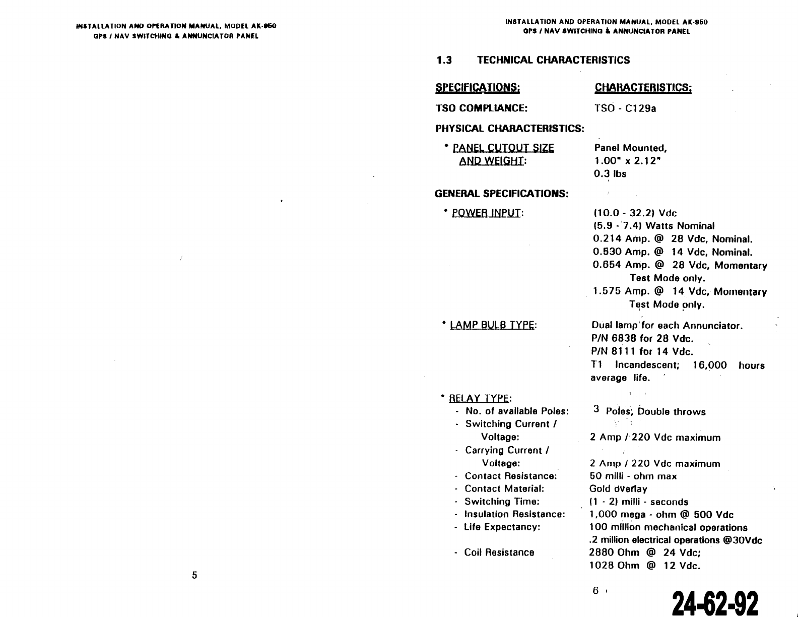
Technical Characteristics
...........
...........................
6
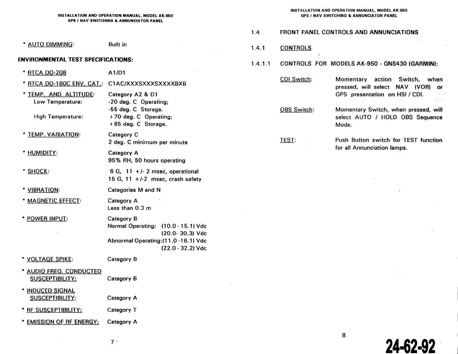
Front Panel Controls and Annunciations .................. 8
Controls
.......................................................
8
Annunciations ............................................... 9
Interface .............. ........................ ................. 10
Equipment Limitations ..........................................
11
Major Components .................. ............... ..............
11
Accessories supplied ................. ....................... ....
11
SECTION
Il
INSTAllATION
AND
TEST
Unpacking and lnspecting Equipment ...................... 1
3
Mechanical Installation .............. .. ..........................
13
Equipment Location ........ ...... ....................... ... 13
Cooling
.........................................................
13
Additional Annunciations .............. ................... 15
Additional
Re
lays ........................................... . 15
Routing
of
Ca
bles ............ ...... ......................... 15
Electrical Installation ............................................. 15
Post Installation Test ....... .. .. ..
..
......... ....................
21
Pre
Installation Tests
.......................................
21
Operating Instructions ............ .. ............ ...........
21
1
3.1
3.2
4.1
4.2
4.3
1.1
2.1
3.1
3.2
3.3
INS
1
AllA
li
UN
ANU
UP~HA
liON
MANUAl,
MUUI:l
AK·!lbU
GPS 1
NAV
SWITCHINO & A'NNUNCIATOR PANEL
TABLE OF CONTENTS (CONT'D)
SECTION
Ill
OPERATION
General
..............................................................
23
Operation
SECTION
IV
WARRANTY
AND
SERVICE
23
Limited Warranty .................................................
25
Repair Service .....................................................
27
Factory Comprehensive Test Service
......................
27
liST
OF FIGURES
Outline Drawing
for
ali Series ...............................• 4
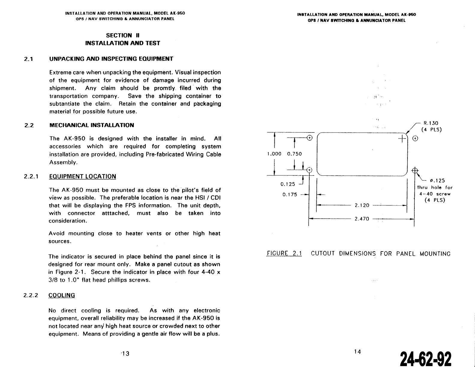
Cutout
Dimensions
for
Panel
Mounting
...................
14
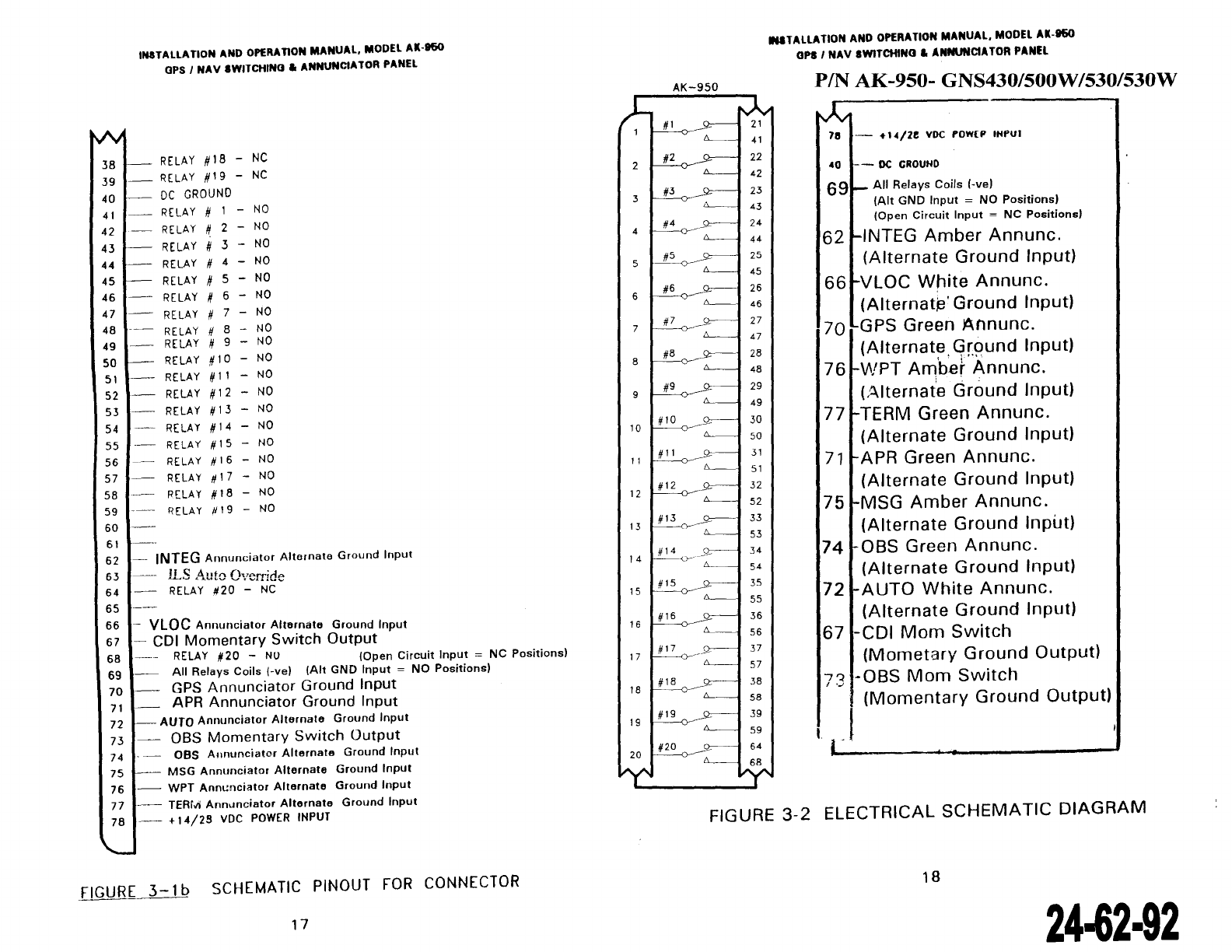
Schematic
Pin
out
for
Connecter ..
_,.......................
16
Electrical Schematic Diagram ................................
18
Wiring Diagram
.......................................
:............ 19
APPENDIX A
Environmental Qualification
for
rn
RTCA 1DO
160C
....
28
2
24-62·92
The document reference is online, please check the correspondence between the online documentation and the printed version.