American Dream Ultra Performance Geothermal Copper Series Manual

25 MAY 2009 Page 1 000744MAN-02
IBDR inc
3960 Howard Hughes Parkway
Las Vegas, Nevada 89169
AMERICAN DREAM Freon-
Copper-Series
Triple Function ™
Installation and Service Manual
Email: info@AmericanDreamGeothermal.com
Web: www.AmericanDreamGeothermal.com
Document Number: 000744MAN-02
Freon-Copper Triple Function
Heat Pumps
REVISION DATE: 25 MAY 2009

Page 2000744MAN-02 25 MAY 2009
SAFETY PRECAUTIONS
WARNING: Ensure all access panels are in place and properly secured before applying power to the unit.
Failure to do so may cause risk of electrical shock.
WARNING: Before performing service or maintenance on the heat pump system, ensure all power sources
are DISCONNECTED. Electrical shock can cause serious personal injury or death.
WARNING: Heat pump systems contain refrigerant under high pressure and as such can be hazardous to
work on. Only qualified service personnel should install, repair, or service the heat pump.
CAUTION: Safety glasses and work gloves should be worn at all times whenever a heat pump is serviced. A
fire extinguisher and proper ventilation should be present whenever brazing is performed.
CAUTION: Venting refrigerant to atmosphere is illegal. A proper refrigerant recovery system must be
employed whenever repairs require removal of refrigerant from the heat pump.
! !
Series:
FCTP = Freon Copper
Triple Function
MODEL NOMENCLATURE
Nominal Size:
2 Ton
3 Ton
4 Ton
5 Ton
Functions:
H = Heating
AC = Active Cooling
W = Domestic Hot Water
Refrigerant:
P = R410a
Voltage Code:
1 = 230-1-60 VAC
2 = 208-3-60 VAC
6 = 220-1-50 VAC
7 = 380-3-50 VAC
Compressor Stages*:
T = 2 Stage
* 2 stage unless unavailable
due to voltage code, refer to
the Electrical Tables.
Air Coil:
S = Standard
Fan Type:
D = Direct Drive
Fan Motor:
E = ECM (Variable Speed)
Fan Discharge:
T = Top
S = Side
Case Style:
V = Vertical
Revision:
01, 02 etc.
FCTF—Size—HACW—P—1T—H—L—SDETV—xx
Extra Loop:
= No
L = Yes
Indoor Coil:
C = Copper
Z = Cupro-Nickel (CuNi)

25 MAY 2009 Page 3 000744MAN-02
APPLICATION TABLE
SIZE FUNCTION REFRIGERANT VOLTAGE STAGES EXTRA
LOOP
INDOOR
COIL
FAN/CASE REVISIONS
3 Ton HACW P
1 T
BLANK
or
H
C or Z SDETV
02
2 T 02
6 S 02
7 T 02
4 Ton HACW P
1 T
BLANK
or
H
C or Z SDETV
02
2 T 02
6 S 02
7 T 02
5 Ton P
BLANK
or
H
C or Z SDETVHACW
1 T 02
2 T 02
6 S 02
7 T 02
This manual applies only to the models and revisions listed in this table

Page 4000744MAN-02 25 MAY 2009
INSTALLATION INFORMATION: ……………….…...………….……………………………………………………………… PAGE 6
Unit description: …………………………………………………………………………………………………..…... Page 6
Unpacking the unit: …………………………………………………………………………………………………... Page 6
Optimum Placement: …………………………………………………………………………………………………. Page 6
Electrical Connections: ……….……………………………………………………………………………………… Page 6
Thermostat Requirements: ………………………………………………………………………………………….. Page 6
Aquastat Requirements: ………………….………………………………………………………………………….. Page 6
FCTF Two-Stage Control Box: ……………...…..………………………………………………………………….. Page 7
Airflow Reduction & Plenum Heater Connections: …….……………………………………………………….. Page 7
Indoor Loop Circulator Wiring: …………………………………………………………………………………….. Page 7
Fan Motor: ……………………………………………………………………………………………………………… Page 7
Control Transformer: …………………………………………………………………………………………………. Page 8
Safety Controls: ………………………………………………………………………………………………………. Page 8
Domestic Hot Water Connections (HACW only): ……………….…..…………………………………………… Page 8
UNIT OPERATION: …………………....……………………………………………………………… PAGE 11
Refrigeration: ………………….…………………………………………………………………………………..…... Page 11
Control Board: …………...………………………………………………….………………………………………... Page 11
SIZING AND DUCTWORK: ………………...…………………………………………………………………………………… PAGE 14
Heat Pump Sizing: ……………………………………………………………………………………………………. Page 14
Duct Systems - General: …………………………………………………………………………………………….. Page 14
Duct Systems - Grill Layout: ………………………………………………………………………………………… Page 14
Thermostat Location: ………………………………………………………………………………………………… Page 15
Plenum Heater (Optional): …………………………………………………………………………………………… Page 15
Condensate Drain: …………………………………………………………………………………………………….. Page 15
Hydronic Systems - General: ……………………………………………………………………………………….. Page 15
Hydronic System Connections: ……………………...…………………………………………………………….. Page 15
Duct Sizing Guide: ……………………………………………………………………………………………………. Page 17
Freon Copper LOOP CONNECTION AND CHARGING: ………..……….………………………………………… PAGE 21
Line Set Interconnect Tubing: …….………………...……………………………………………………………… Page 21
Pipe Insulation: ………………………………………………………………………………………………………… Page 21
Silver Soldering Line Sets: ……..……………………………………………………………………………………. Page 21
Pressure Testing: ……………………………………………………………………………………………………… Page 21
Vacuuming the System: ……...………………………………………………………………………………………. Page 21
Charging the System: ………...………………………………………………………………………………………. Page 21
STARTUP PROCEDURE: ………………………………………………………………………………………………………. Page 23
Pre-start Inspection: …………………………………………………………………………………………………. Page 23
Unit Startup (Air): ……….………,...…………………………………………………………………………………. Page 24
Startup Record (Air): …………………………………………………………………………………………………. Page 25
Unit Startup (Hydronic): ………..,...…………………………………………………………………………………. Page 26
Startup Record (Hydronic): ………...………………………………………………………………………………. Page 27
HEATING TXV ADJUSTMENT: ………..…………….…………………………………………………………………………. Page 28
Adjustment Procedure: ……...………………………………………………………………………………………. Page 28
Heating TXV Adjustment Record: ……….…………………………………………………………………………. Page 29
GENERAL MAINTENANCE: ……………………...…………….……………………………………………………………… PAGE 30
TROUBLESHOOTING GUIDE: ………………………………….……………………………………………………………… PAGE 31
Repair Procedures: …………………………………………………………………………………………………… Page 44
Refrigeration Circuit Diagrams: ……………………………………………………………………………………. Page 45
MODEL SPECIFIC INFORMATION: …………………..………………………………………………………………………. PAGE 48
Standard Capacity Ratings: …………..……………………………………………………………………………. Page 48
Capacity Ratings: ……………………….....…………………………………………………………………………. Page 49
Electrical Tables: ……………………………………………………………………………………………………… Page 52
Electrical Diagrams (230-1-60): ………..…………………………………………………………………………… Page 53
Case Details: ………………………...………………………………………………………………………………… Page 55
APPENDIX A: ECM Fan Airflow Tables: ……………………………………………………………………………………. PAGE 57
WARRANTY INFORMATION: ………………………………………………………………………………………………….. PAGE 60
Table of Contents

25 MAY 2009 Page 5 000744MAN-02
Tables, Diagrams and Drawings
TABLES
Table 1 - Thermostat to FCTF Control Box Signals: ………..………………………...………………..…….... Page 6
Table 2 - Aquastat to FCTF Control Box Signals: ……….…..………………… ……………………..…….... Page 6
Table 3 - Typical Aquastat Settings: …………………………..…………………………………………..…….... Page 7
Table 4 - FCTF Two-Stage Control Box to Heat Pump Signals: ………….…………………………..…….... Page 7
Table 5 - Remaining Signal Descriptions: ……………..……..…………………………………………..…….... Page 7
Table 6 - Airflow Selections: ………………………………………………………………………………………... Page 7
Table 7 - Cooling Mode Loop Sequences: ………………………………………………………………………... Page 11
Table 8 - Cooling Loop Configuration: ………………………………………….…………………………….…... Page 11
Table 9 - RS232 Port Configuration: ……………....……………………………………………….……………... Page 12
Table 10 - Control Board Commands: …………………..……….……………..…………………………….…... Page 12
Table 11 - Control Board Default Settings: …..………….………………………….……………………….…... Page 12
Table 12 - Heat Pump Size vs. Heated Area: …………………………………….………………………..……... Page 14
Table 13 - Heat Pump Size vs. Hot Air Grills: …..………………………………….……………………..……... Page 14
Table 14 - Plenum Heater Sizing: …..…………..…………………………………..……………………………... Page 15
Table 15 - Duct Sizing Guide: ………………………..…………………………...………………………………... Page 17
Table 16 - FCTF Charge Chart: …….…………………………………………………...…………………………... Page 21
Table 17 - Heating TXV Adjustment Record Column Descriptions: …….…………………………………... Page 28
Table 18 - Standard Capacity Ratings - Heating 60Hz: ………………………..…..…………………………... Page 48
Table 19 - Standard Capacity Ratings - Cooling 60Hz: …………….…………………………...……………... Page 48
Table 20 - Standard Capacity Ratings - Hydronic Heating 60Hz: …………….……………...……………... Page 48
Table 21 - Heat Pump Electrical Information (230-1-60): …..…………………….….………………………... Page 52
Table 22 - Heat Pump Electrical Information (208-3-60): …..…………………….….………………………... Page 52
Table 23 - Heat Pump Electrical Information (220-1-50): …..…………………….….………………………... Page 52
Table 24 - Heat Pump Electrical Information (380-3-50): …..…………………….….………………………... Page 52
DIAGRAMS
Case Details: ……………………..…………………….………………………………………………………….….. Page 55
DRAWINGS
000344CDG - Typical Heating Only Zone Connection Diagram (TF&FCTF-Series): …...…………..…….. Page 9
000484PDG - Single Unit Connection to DHW Pre-Heat Tank: ……………………………………………….. Page 10
000310CDG - NCB Laptop Communication Cable: ………………………….………………………………….. Page 13
000606CDG - Typical Duct and Condensate Connections (Vertical Case): ….…………….………………. Page 16
000533PDG - Typical Buffer Tank Configuration - Four Port Tank: ……..………………………………….. Page 18
000530PDG - Typical Zone Types for Hydronic Applications: ……………………………………………….. Page 19
000627PDG - Single Unit Connection to On-Demand DHW Pre-Heat Tank: ……………………………….. Page 20
000769PDG - DX Line Set Interconnect Tubing Installation (R410a): …….…..……………………………… Page 22
000268RCD - FCTF-Series Refrigeration Circuit Diagram—Heating Mode: …….…………...…..………… Page 45
000268RCD - FCTF-Series Refrigeration Circuit Diagram—Cooling Mode: …….……………….………… Page 46
000269RCD - FCTF-Series Refrigeration Circuit Diagram—Hydronic Heating Mode: …...…….………… Page 47
000737SCH - FCTF-**-HAC*-P-1T-*-*-*DE** Schematic Diagram: ………………...………...…………..…… Page 53
000738ELB - FCTF-**-HAC*-P-1T-*-*-*DE** Electrical Box Diagram: …………………..…..………..……… Page 54

Page 6000744MAN-02 25 MAY 2009
UNIT DESCRIPTION
Your American Dream Geothermal unit is a high efficiency
two stage triple function heat pump with R410a refrigerant. It
extracts and rejects heat from the earth via direct contact with
copper loops, eliminating the need for a secondary heat ex-
changer and associated components. The FCTF unit can pro-
vide air heating, air cooling, and hydronic heating.
Freon Copper units require less “loop” per ton and are
more efficient than conventional ground loop systems. The re-
duced thermal resistance between the earth and the refrigerant
circuit provides better heat transfer, resulting in a higher suction
pressure and increased output.
An electrically commutated (ECM) fan with several speed
options is standard. The motor has a soft start function for im-
proved efficiency and reduced wear.
The unit has several key features that are described in the
specifications document for the particular heat pump. Please
request a copy if desired or visit
www.AmericanDreamGeothermal.com
UNPACKING THE UNIT
When the heat pump reaches its destination it should be
unpacked to determine if any damage has occurred during
shipment. Any visible damage should be noted on the carrier's
freight bill and a suitable claim filed at once.
The heat pump is well constructed and every effort has
been made to ensure that it will arrive intact, however it is in the
customer's best interest to examine the unit thoroughly when it
arrives.
OPTIMUM PLACEMENT
For air units, to achieve the greatest efficiency, the heat
pump should be centrally located in the home with respect to the
conditioned space. This design provides the utmost in economy
and comfort and usually can be accomplished in harmony with
the design of the home. A heating system cannot be expected to
produce an even warmth throughout the household when it is
located at one end of the structure and the warm air is
transmitted with uninsulated metal ductwork.
If possible the access panels should remain clear of
obstruction for a distance of two feet to facilitate servicing and
general maintenance.
Raising the heat pump off the floor a few inches is generally
a good practice since this will prevent rusting of the bottom
panel of the unit. We recommend that the heat pump be placed
on a piece of 2'' thick styrofoam. The styrofoam will smooth out
any irregularities in the cement floor and deaden any
compressor noise emitted from the bottom of the cabinet.
AMERICAN DREAM Ultra Performance® heat pumps have
an air-filter rack which can be installed with the removable end
(where the filter is inserted) on either side to facilitate changing
the filter.
ELECTRICAL CONNECTIONS
The heat pump has a concentric 1.093” / 0.875” knockout
for power supply connection to the electrical box, as well as one
for connection to the circulator pump module for ground loop
applications. There are two 1/2” openings with plastic grom-
mets (grommet hole is 3/8”) in the upper section of the electrical
box, one for the thermostat connections, and one for the op-
tional plenum heater connections.
A schematic diagram and electrical box layout diagram
(ELB) can be found inside the electrical box cover of the unit as
well as in the Model Specific section of this manual. The Electri-
cal Tables in the Model Specific section and the ELB diagram
contain information about the size of wire for the connections, as
well as the recommended breaker size. A properly qualified
electrician should be retained to make the connections to
the heat pump and associated controls. The connections to
the heat pump MUST CONFORM TO LOCAL CODES.
THERMOSTAT REQUIREMENTS
The FCTF-Series unit includes a three-stage heating and
two stage cooling thermostat with relay outputs for proper air
mode operation. Triac output thermostats are incompatible
with the control board in the heat pump. The stages are S1
= heat pump stage 1 , S2 = heat pump stage 2S3 = electric aux-
iliary (heating only). One can be purchased with the unit, or
other thermostats with the same number of stages can be used.
The thermostat signals connect to the geothermal unit Control
box as per TABLE 1.
AQUASTAT REQUIREMENTS
For water mode operation, a two stage aquastat is re-
quired to provide the appropriate control signals. The connec-
tions to the FCTF Control Box are shown in TABLE 2.
The aquastat can be placed anywhere within the range of
the probe cable. The probe should be inserted into a dry well in
or near the top of the tank for optimal operation (refer to draw-
ing 000533PDG). If a dry well is not available, it may be possi-
ble to fix the probe to the tank inside the insulation.
Installation Information
TABLE 1 - Thermostat to FCTF Control Box Signals
Signal Description
C 24VAC Common (Ground)
G Fan low speed (for air circulation)
Y1Heat Pump Stage 1 (Compressor stage 1)
RH24VAC Hot
L Fault (24VAC when fault condition)
W2Heat Pump Stage 3 (auxiliary heat) / Emer-
gency Heat
O/B/W1Cooling Mode (reversing valve)
Y2Heat Pump Stage 2 (Compressor stage 2)
TABLE 2 - Aquastat to FCTF Control Box Signals
Signal* Description
CA 24VAC Common (Ground)
RA 24VAC Hot
Y1A Heat Pump Stage 1 (Compressor stage 1)
Y2A Heat Pump Stage 2 (Compressor stage 2)
* Refer to 000139CDG (included with the FCTF Control Box)
for a complete description of the connections to the aquastat.

25 MAY 2009 Page 7 000744MAN-02
TABLE 3 shows typical settings for the aquastat. The
settings may be changed as desired; however, the setpoint
should not exceed 120°F (49°C); Exceeding this setpoint limit
will cause the heat pump operating pressures to approach the
safety control settings, possibly causing nuisance shut downs.
If only floor zones are being heated, it is highly rec-
ommended to drop each of the setpoints by 15°F (8°C) for
increased efficiency.
It is recommended that a buffer tank with electric elements
be selected to provide auxiliary / backup heat. The tank ele-
ment thermostats can be set to a low value of around 60°F
(15°C) which will prevent the hydronic system from becoming
too cold should there be a failure in the heating system.
Drawing 000344CDG shows how a typical zone system
would be setup with the FCTF unit. The zone controls and heat
pump operate independently, there are no connections between
the two systems.
TWO STAGE CONTROL BOX
The Two Stage Control Box is the interface between the
controls (thermostat and aquastat) and the heat pump. It’s main
function is to provide the signal manipulation required to operate
the fan or the Indoor Loop Circulator as required based on the
signals received from the controls. It also contains a contactor
for power connections to the Indoor Loop Circulator.
The connections between the control box and the heat
pump are shown in TABLE 4. Three documents are shipped
with the Control Box: 000739SCH, 000740CDG and
000741INF. They contain all the information required to com-
plete the Two Stage Control Box connections, as well as infor-
mation on how the control box operates.
AIR FLOW REDUCTION AND
PLENUM HEATER CONNECTIONS
TABLE 5 lists the remaining four terminals on the heat
pump terminal strip. These signals are separate from the Con-
trol Box. The AR1and AR2terminals are the airflow reduction
signal. See the FAN MOTOR section for more information on
therm. The I and 1 terminals are the dry contacts for the plenum
heater. Connect these to the C and 1 terminals of the plenum
heater. Refer to the electrical box diagram (ELB) of the heat
pump or the diagram on the cover of the plenum heater for more
information.
NOTE: Some models are not available in two-stage at the pre-
sent time (see Electrical Tables). The Y2 signal is not used for
these units
INDOOR LOOP CIRCULATOR WIRING
The Indoor Loop circulator provides flow between the heat
pump and the buffer tank. The Two Stage Control Box has pro-
visions for connecting the Indoor Circulator so that it will be
turned on whenever the heat pump is in water heat mode and
the compressor operates. Connect line voltage (115 or
230VAC) to the terminals marked L1 and L2 of the Indoor Circu-
lator Contactor. Connect the Indoor Loop circulator to the termi-
nals marked P1 and P2. Ensure that the line voltage and circu-
lator voltage rating are the same.
FAN MOTOR
The unit is equipped with a direct drive ECM fan motor for
maximum efficiency. The motor features a soft start which fur-
ther improves efficiency by eliminating inrush current and pro-
vides a smooth, quiet ramp up to speed . The motor will main-
tain the programmed air flow up to the maximum external static
value. Refer to the APPENDIX A: ECM Fan Airflow Tables.
The air flow can be set to four different levels by changing
the position on the Air Flow board located in the electrical box.
The four levels are indicated in TABLE 6. The actual air flow
TABLE 6 - Airflow Selections
Position Airflow
LOW -12%
MED -6%
HIGH Nominal
MAX +6%
TABLE 4 - FCTF Two Stage Control Box to Heat
Pump Signals
Signal Description
C 24VAC Common (Ground)
G Fan low speed (for air circulation)
Y1Heat Pump Stage 1 (Compressor stage 1)
RH24VAC Hot
L Fault (24VAC when fault condition)
W2Heat Pump Stage 3 (auxiliary heat) / Emergency
Heat
O/B/W1Cooling Mode (reversing valve)
Y2Heat Pump Stage 2 (Compressor stage 2
E1 Fan Auxiliary/Emergency Speed Control (In)
E2 Fan Auxiliary/Emergency Speed Control (Out)
FC Fan Contactor
TABLE 5 - Remaining Signal Descriptions
Signal Description
AR1Airflow Reduction*
AR2Airflow Reduction*
I Plenum Heater dry contact
1 Plenum Heater dry contact
* Connect AR1to AR2with a dry contact to reduce the airflow
by 15%. Refer to the Fan Motor sub-section for more infor-
mation.
TABLE 3 - Typical Aquastat Settings
Stage 1** Stage 2**
Item °F °C °F °C
Setpoint 115 46 105 41
Delta 5 3 5 3
Activation * 110 43 100 38
*Activation is indirectly set by the Setpoint and Delta values
** All values must be set identical for both stages

Page 8000744MAN-02 25 MAY 2009
values can be found in APPENDIX A.
Units are shipped with the MED position selected for
nominal air flow. The air flow can be further reduced by 15% by
making a dry contact across AR1and AR2on the terminal strip.
This can be used for applications that have multiple zones, or
retrofits with undersized ductwork, to help reduce air flow noise
in the ductwork. It is recommended that airflow reduction only
be used with the High or Max air flow setting. Care should be
taken to ensure that the unit does not trip a safety control in
heating or cooling mode if the 15% reduction is used in conjunc-
tion with the Med or Low air flow setting.
CONTROL TRANSFORMER
The low voltage controls for all models are powered by a
100VA transformer with primary and secondary fuses for circuit
protection. Should a fuse blow, determine the problem and rec-
tify it before replacing the fuse.
SAFETY CONTROLS
The heat pump has two built in safety controls which are
designed to protect the unit from situations which could damage
it should the operation of the refrigeration circuit fall outside the
allowable operating range.
A. Low Pressure Control
The low pressure control monitors the compressor suction
pressure and will shut the compressor down if the refrigerant
evaporating pressure becomes too low.
There only reason this control would activate in response
to the operating conditions of the unit in the heating mode
would be due to a ruptured loop, causing a low refrigerant
charge. Any other low pressure trips would be due to a fault in
the unit.
B. High Pressure Control
The high pressure safety control monitors the compressor
discharge pressure and will shut the compressor down if the
condensing pressure becomes too high.
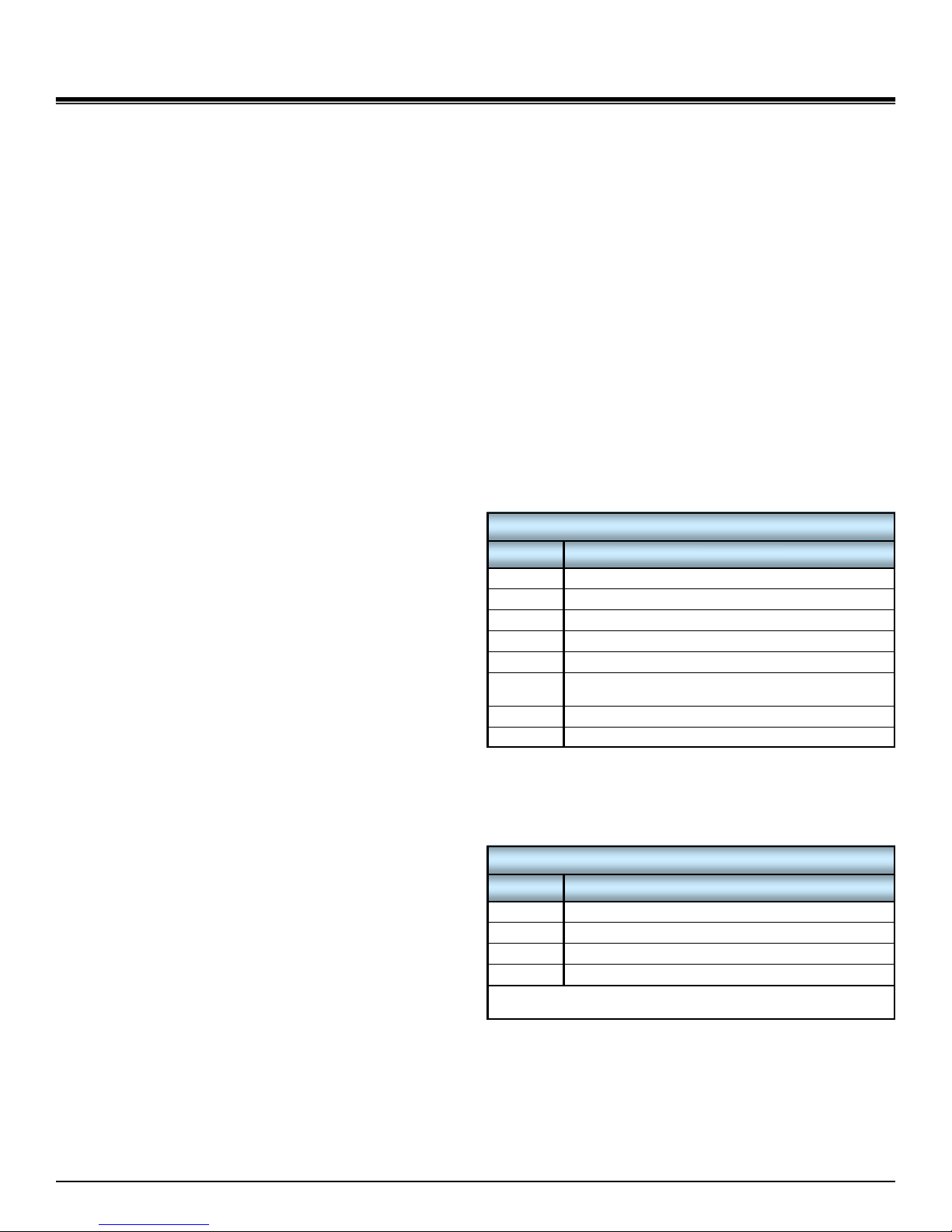
There are (3) main reasons why this control would activate
in response to the operating conditions of the unit while operat-
ing in heating mode:
1. Low or no airflow (or water flow).
2. High return air temperature (or water temperature).
3. Dirty air coil due to poor filter maintenance.
Each of the controls are auto-reset controls. There is also
a manual reset high pressure control should the control board
be faulty and fail to disengage the compressor. It can be reset
by pressing the rubber button on the end of it. It is electrically
located between the Y output of the control board and the com-
pressor contactor coil.
The control board (see next section) monitors the pressure
controls and shuts the compressor off immediately for a set pe-
riod of time (adjustable) should there be a fault. The counter for
the safety control in question will be increased by 1. The LED
indicator for the control will flash until the control is reset as the
pressures equalize in the unit. The unit may restart after the
timer period has expired. Should the unit trip on the safety con-
trol again , the compressor will once again shut down and the
counter will be incremented by one again. Each time this occurs
the count is incremented until the counter reaches the max
value (default is 3) at which point a permanent lockout will occur
if this occurred within a set period of time (default 6 hours) and
the compressor cannot be started again until the control board is
reset by shorting the reset pins together or turning the power off
and on again. The lockout count is decreased after a set period
of time (default 6 hours) if there are no more occurrences.
If the control board enters permanent lockout mode there
is a serious problem with the system and it must be rectified if
the unit is to maintain good service.
DOMESTIC HOT WATER
CONNECTIONS
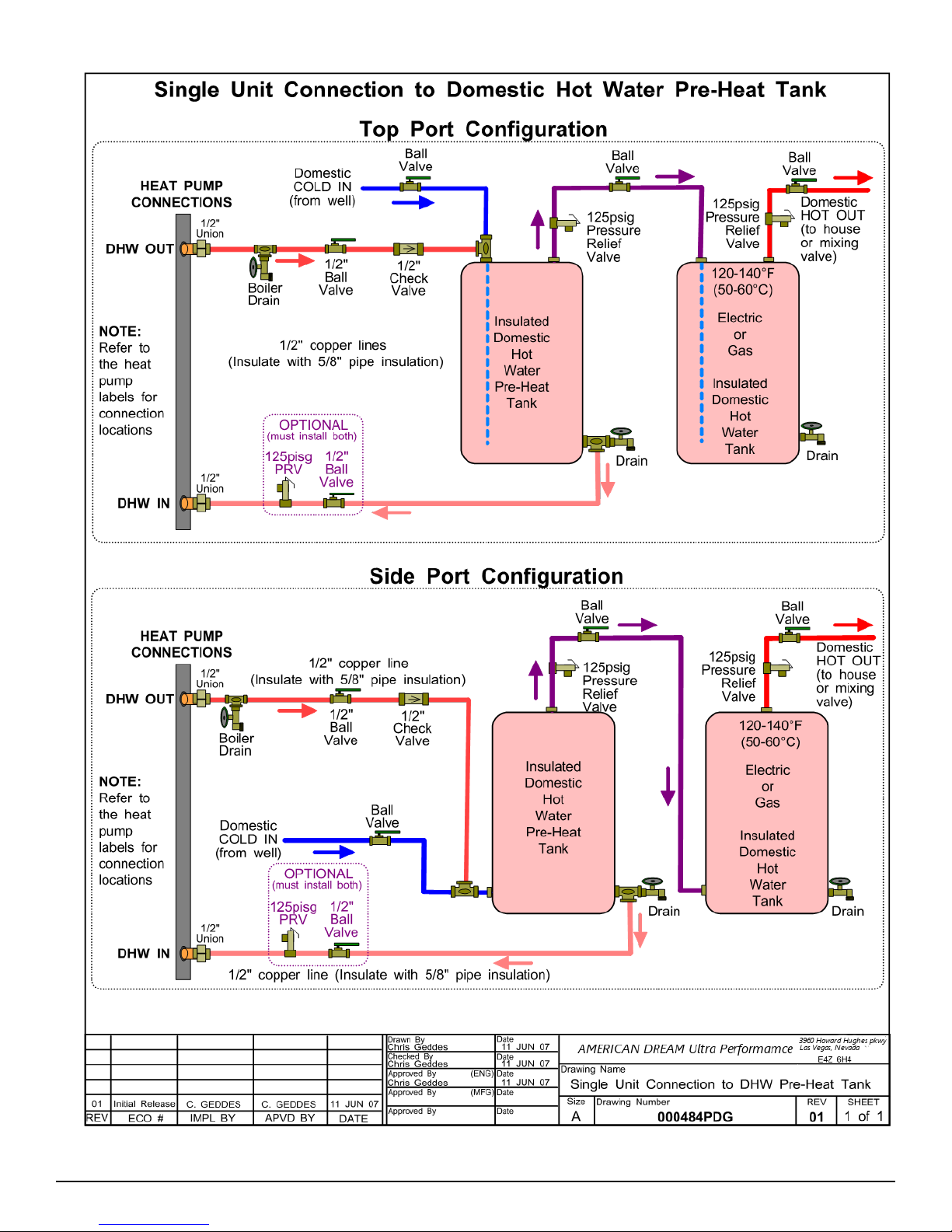
A typical piping diagram for a pre-heat tank configuration
can be found in drawing 000484PDG at the end of this
section. Be sure to note the position of the check valve
and the direction of water flow. Other configurations are possi-
ble, and there may be multiple units tied together in larger build-
ings.
WARNING: USE ONLY COPPER LINES TO
CONNECT THE DESUPERHEATER. TEMPERATURES
COULD REACH 200F SHOULD THE DHW
CUTOUT SWITCH FAIL, POTENTIALLY RUPTURING
PEX PIPING.
Ensure the tank is filled with water and under pressure
before activating the heat pump. Slightly loosen the boiler
drain on the DHW Out pipe to allow air to escape from the
system before the unit is started. This step will make certain that
the domestic hot water circulator in the unit is flooded with water
when it is started.
CAUTION: the domestic hot water pump is water lubricated;
damage will occur to the pump if it is run dry for even a
short period of time.
Connect the brown wire with the blue insulated terminal to
L1 of the compressor contactor. Ensure the power is off
when connecting the wire.
The DHW loop may have to be purged of air several times
before good circulation is obtained. A temperature difference
between the DHW In and DHW Out can be felt by hand when
the circulator pump is operating properly.
For the pre-heat tank setup, the final tank should be set to
140°F(60°C), unless local code requires a higher setting. The
pre-heat tank does not require electric elements. This setup
takes full advantage of the desuperheater as it is the sole heat
provider to the pre-heat tank. The desuperheater remains active
during the compressor runtime until the pre-heat tank has been
completely heated by the desuperheater alone. This setup is
more energy efficient than a single tank setup.
CAUTION: If two (2) shut-off valves are located on the do-
mestic hot water ines as shown in the diagram, a pressure
relief valve must be installed to prevent possible damage to
the domestic hot water circulator pump should both valves
be closed.
!
!

25 MAY 2009 Page 9 000744MAN-02

Page 10000744MAN-02 25 MAY 2009

25 MAY 2009 Page 11 000744MAN-02
REFRIGERATION
Freon Copper operation is essentially the same as any
other heat pump. The main difference is in the outdoor loop
section. Freon Copper heat pumps eliminate the intermediate
ground loop exchanger and pumping equipment by using cop-
per loops to interact directly with the earth. For each ton of ca-
pacity, the evaporator (heating mode) consists of one three-way
valve, one heating thermostatic expansion valve (TXV), a pair of
check valves and one outdoor copper loop with one vapour and
one liquid connection to the heat pump. For each additional ton
of capacity, there is a parallel evaporator circuit added to the
unit.
In heating mode, all loops are used simultaneously to cre-
ate a large evaporator. This allows maximum heat transfer from
the loop field. Since each loop has it’s own TXV, its superheat
can be individually tailored, allowing each loop to obtain the
same superheat even it may have different soil conditions. The
loop select valves default to open in heating mode, and as such
none of the loop select valve solenoid coils are energized.
In cooling mode, running all loops at the same time would
create far too large a condenser and the unit would have very
low head pressure, causing the suction pressure to fall off until
the low pressure safety control was reached. To circumvent this
problem, the direct expansion unit will begin cooling mode by
using only Loop 1.
Loops are selected by activating the solenoid on the loop
select valve for the loop in question. The remaining loops are
scavenged to the suction line.
Using one loop greatly reduces the size of the condenser,
allowing the unit to operate properly. As the ground tempera-
ture warms up, rejecting the heat to the ground becomes more
difficult, causing the head pressure to increase. When the loop
is sufficiently hot enough to reach the Loop Switch set point
(480psig), the unit will switch to Loop 2. This starts the cycle
over with a new loop and allows the previous loop time to re-
cover. Heat pump operation will continue, switching through the
loops as required.
The time between loop changes is monitored and should it
fall below the adjustable threshold (default 15 minutes), indicat-
ing that the loops are sufficiently hot, the heat pump will begin
using two loops at a time, and continue cycling. If the loop
switch time falls below the threshold on two loop mode, the
soaker hose will be turned on (if installed). The soaker hose
cools the loops down with water. The loop sequences are
shown in TABLE 7.
As the transition from summer to fall begins and the cool-
ing load is greatly reduced, the loops begin to cool down on their
own. Eventually a point is reached at which the loops are
cooled down enough that two loops becomes too large a con-
denser. This may occur naturally or there may be a few heating
days and then a warm spell again (the loops settings are not
affected by a switch to heating mode). Two loop operation can
no longer be sustained and the unit will trip the low pressure
safety control. This occurrence will set the heat pump back to
one loop mode and allow the unit to run properly when it auto-
matically restarts after the lockout timer expires.
CONTROL BOARD
All heating / cooling units contain a control board that
monitors the thermostat signals, safety controls and loop pres-
sures. It controls the operation of the compressor, fan and aux-
iliary / emergency heat. It also activates the reversing valve and
controls the loop sequencing when in cooling mode. Heating
only units do not have a control board.
The number of cooling loops must be configured (done at
the factory). There are two jumpers to the top right of the micro-
controller. The configuration is shown in TABLE 8.
There is also a jumper marked DEFAULT that should be
left in place. The jumper marked IF NO B TERMINAL should be
left place as well unless the thermostat used has a B terminal
that is constantly powered in heating mode.
The control board has 4 connectors: one for the thermostat
connections; one for the heat pump component connections;
one for the loop solenoid connections; and one for the safety
control and loop pressure switch connections. There are also
several LEDs to indicate the status of the control board. Refer
to drawing 000301CDG for the location of the connectors and
LEDs.
The Heart Beat LED flashes once every second. This indi-
cates that the control board is operational. An on-board COP
watchdog timer resets the microprocessor should anything af-
fect code execution.
The high and low pressure control LEDs flash once per
second when a control is open. They will stay on if there is a
permanent lockout.
The loop switch LED will come on when the loop pressure
switch is activated. Note that the loop switch is only for cooling
mode, it does not affect heating mode operation.
There is a compressor short-cycle timer (default 2 minutes)
and also a mode switch timer (default 5 minutes). Both are ad-
justable through the control board communications port.
TABLE 8 - Cooling Loop Configuration
# of Loops Left Jumper Right Jumper
2 OFF OFF
3 ON OFF
4 OFF ON
5 ON ON
AMERICAN DREAM Geothermal Unit Operation
TABLE 7 - Cooling Mode Loop Sequences
# of
Loops 1 2 3 4 5 6
2 1 & 2
3 1 & 2 2 & 3 1 & 3
4 1 & 2 3 & 4
5 1 & 2 3 & 4 1 & 5 2 & 3 1 & 3 4 & 5

Page 12000744MAN-02 25 MAY 2009
The high pressure, low pressure and loop switch are 5VDC
signals. The low pressure control connects to L and L on the
control board. The high pressure control connects to H and H.
The loop switch connects to S and S. All other inputs and out-
puts are 24VAC.
When the thermostat calls for heat, the compressor will
start (Stage 1), as will the fan after a short delay (adjustable).
The unit will run until the thermostat is satisfied and the unit
shuts off (the fan will continue to run for an adjustable period);
or, a set period of time elapses (default 40 minutes). Should the
set period elapse, the auxiliary heat (Stage 2) will be engaged to
help the unit on cold days when the load is too large for the unit.
When the thermostat calls for cooling, the compressor will
start (Stage 1), as will the fan after a short delay (adjustable).
The unit will run until the thermostat is satisfied and the unit
shuts off (the fan will continue to run for an adjustable period).
During operation, the control board will cycle through the loops
as required.
The control board has an RS-232 communications port on
board. A simple program such as Hyper Terminal and an
adapter cable can be used to communicate with the control
board. Drawing 000301CDG shows how to build the communi-
cations cable. The port settings are shown in TABLE 9. The
commands available are listed in TABLE 10. Note that the COP
must be unlocked by command U before using command C to
change system settings. The list of settings for command C is
shown in TABLE 11. It is recommended that the settings be left
at the defaults values.
TABLE 9 - RS232 Port Configuration
Item Setting
Baud 9600
Data Bits 8
Parity None
Stop Bits 1
Flow Control Xon / Xoff
TABLE 10 - Control Board Commands
Command Description
H Help - displays the list of commands
U Lock / unlock the COP watchdog
L Display loop status
M Display loop history
S Display system status
D Display system configuration
C Change system settings (use U first)
T System runtimes
! Advance system time by 59 minutes
Z Reset loop timers to zero
TABLE 11 - Control Board Default Settings
Command Air Unit
Blower wait time after comp. start 2sec
Blower run time after comp. stops 5sec
Blower run time after aux. heat off 59sec
Aux. heat on time after comp. on 40min
Comp. off if low lockout (HEAT) 5min
Comp. off if low lockout (COOL) 30min
Comp. off if high lockout (HEAT) 5min
Comp. off if high lockout (COOL) 30min
Comp. off time between heat & cool 5min
Comp. delay since being off 2min
Min. loop time before mode increase 15min
Loop pressure testing wait time 7sec
Soaker start after comp. on time 2hrs
Soaker hose run time (maintenance) 4hrs
Soaker hose run time (emergency) 12hrs
System check interval 2sec
Low pres. lockout counter reduce time 6hrs
High pres. lockout counter reduce time 6hrs
Low pres. lock ignore counter 3 times
High pres. lock ignore counter 3 times
Reset mode = 1 and loop memory time 2 weeks
Maximum mode to be allowed 2
Ignore low pres. for 5min
Ignore low pres. for 0sec

25 MAY 2009 Page 13 000744MAN-02

Page 14000744MAN-02 25 MAY 2009
A duct system capable of supplying the required air flow is of
utmost importance. AMERICAN DREAM Geothermal
recommends that the static pressure be kept below 0.2 inches
of water total. In some instances the number of floor diffusers
will actually double when compared to the number that would be
used for a hot air oil-fired furnace. Refer to TABLE 15 at the
end of this section.
1. Generally allow 100 cfm for each floor grill.
2. All leads to the grills should be 6'' in diameter (28sq.in. each).
3. The main hot air trunks should be at least 75% of the square
surface area of leads being fed at any given point.
4. Return air grills should have a minimum of the same total
square surface area as the total of the supply grills.
5. The square surface area of the return trunks should equal
the square surface area of the grills being handled at any
given point along the trunk.
It is VERY IMPORTANT that all turns in both the supply
trunks and the return trunks be made with TURNING RADII. Air
act like a fluid and, just like water, pressure drop is increased
when air is forced to change direction rapidly around a sharp or
irregular corner.
It is recommended that flexible collars be used to connect the
main trunks to the heat pump. This helps prevent any vibrations
from travelling down the ductwork. If a plenum heater is in-
stalled, the collar should be at least 12” away from the heater
elements.
The first 5-10 feet of the main supply trunks should be insu-
lated with acoustical duct insulation to further inhibit any noise
from the unit from travelling down the ductwork. If a plenum
heater is installed, insulation should not be placed within 12” of
the heater elements.
Drawing 000606CDG shows a typical installation.
DUCT SYSTEMS - GRILL LAYOUT
Most forced air heating systems in homes have the floor grills
placed around the perimeter of the room to be heated. Supply
grills should be placed under a window when possible to help
prevent condensation on the window. As mentioned in the pre-
vious sub-section, supply grill leads should be 6'' in diameter (28
sq.in. each) to allow 100cfm of air flow.
In a typical new construction, there should be one supply
grill for every 100sq.ft. of area in the room. When rooms require
more than one grill, they should be placed in a manner that pro-
motes even heat distribution, such as one at each end of the
room. It is always a good idea to place a damper in each grill
supply or place adjustable grills so that any imbalances in the
heat distribution can be corrected.
HEAT PUMP SIZING
TABLE 12 depicts averages *WILL VARY WITH ENVELOP
EFFICIENCY* as a rough guideline to the size of home
each heat pump size can handle.
THE TABLE ABOVE IS FOR INFORMATION ONLY, IT
SHOULD NOT BE USED TO SELECT A UNIT SIZE. It simply
shows on average what size unit is required for a typical two-
level home (main level and below grade basement) with R-20
walls, R-40 ceiling and average size and number of windows.
The Heated Area is the area of the main level, The tables ac-
count for a basement the same size as the heated area.
AMERICAN DREAM Geothermal HIGHLY RECOMMENDS
THAT A PROPER HEAT LOSS/GAIN ANALYSIS BE PER-
FORMEDE BY A PROFESSIONAL INSTALLER WITH CSA
APPROVED SOFTWARE BEFORE SELECTING THE SIZE OF
UNIT REQUIRED FOR THE APPLICATION. For heating
dominant areas, we recommend sizing the unit to 100% of
the heating design load for maximum long term efficiency
with minimal supplementary heat. The unit should be in-
stalled as per CSA 448.2-02.
There are many factors to consider when sizing the heat
pump. Some of these factors include the number of levels, the
size of the windows, the orientation of the home, attached ga-
rage, bonus rooms, walk-in basement, coldest outdoor tempera-
ture, etc. The heat loss program will take all of these factors into
consideration in its calculations. An undersized installation will
not be as efficient and will require expensive supplementary
heat to maintain a comfortable temperature in the home, and the
cost savings of having a geothermal heat pump are greatly re-
duced.
Once the total heat loss has been calculated, the unit can
be sized using the performance tables (from the specifications
document) in conjunction with the minimum expected entering
liquid temperature of the ground loop (well water temperature for
ground water system). The heat pump output must be able to
match the total heat loss at the selected entering water tempera-
ture in order to provide a comfortable environment with minimal
auxiliary heat.
DUCT SYSTEMS - GENERAL
Ductwork layout for an AMERICAN DREAM heat pump will
differ from traditional hot air furnace design in the number of
leads and size of main trunks required. Air temperature leaving
the heat pump is normally 95º -105ºF (35-40ºC),much cooler
than that of a conventional warm air furnace. To compensate for
this, larger volumes of lower temperature air must be moved
and consequently duct sizing must be able to accommodate the
greater air flow without creating a high static pressure or high
velocity at the floor diffusers.
Sizing and Ductwork
TABLE 13 - Heat Pump Size vs. Hot Air Grills
Size (tons) # of Grills (@100cfm)
2 11
3 14
4 17
5 21
TABLE 12 - Heat Pump Size vs. Heated
Area
Size (tons) Sq.ft. Sq.m.
2 1,000 100
3 1,400 130
4 2,000 185
5 2,600 240

25 MAY 2009 Page 15 000744MAN-02
The total number of supply grills available is based on the
heat pump nominal airflow. TABLE 13 shows the number of
grills available per heat pump size.
Return grills should be mounted on the floor. At minimum
they should be the same size as the supply grill, it is highly
recommended that they be 25% to 50% larger than the total
supply. They should be placed opposite the supply grills when
possible to ensure distribution across the room. For rooms re-
quiring more than one supply grill, it may be possible to use one
larger return grill if it can be centrally positioned opposite of the
supply grills, however it is preferred to have one return for each
supply to maximize heat distribution across the room.
THERMOSTAT LOCATION
Most homes are a single zone with one thermostat. The ther-
mostat should be centrally located within the home, typically on
the main floor. It should be placed away from any supply grills,
and should not be positioned directly above a return grill. Most
installations have the thermostat located in a hallway, or in the
inner wall of the living room. It should be noted that most
homes do not have any supply ducts in the hallway. This can
lead to a temperature lag at the thermostat if there is very little
air movement in the hallway, causing the home to be warmer
than indicated by the thermostat.
PLENUM HEATER (OPTIONAL)
For installations that do not already have a backup heat
source such as electric baseboard, wood stove, propane etc, it
is recommended that a plenum heater be installed. This pro-
vides two functions.
The first function of the plenum heater is to act as an auxiliary
heat source. As such it will provide additional heat on extremely
cold days if the heat pump is unable to bring the home tempera-
ture up quickly enough, eliminating any discomfort to the home-
owner.
The second function of the plenum heater is to provide emer-
gency heat should a problem occur that causes the heat pump
to be locked out. This can be engaged by setting the thermostat
to emergency heat, allowing the plenum heater to function while
preventing the heat pump from operating. Should the heat
pump fail while the home is vacant, the auxiliary function of the
thermostat will maintain the temperature setting of the thermo-
stat.
The plenum heater is powered separately from the heat
pump. Only two control wires are needed to connect the ple-
num heater to the heat pump. Refer to the label on the plenum
heater or the electrical box diagram on the inside of the electri-
cal box cover of the unit for details on the connections.
The plenum heater should be mounted in the supply duct in a
manner that allows all of the airflow to pass through it to prevent
any hot spots in the heater elements.
TABLE 14 shows the recommended size plenum heater, as
well as the wire size and breaker size needed to provide power
to the plenum heater.
CONDENSATE DRAIN
The unit comes equipped with a 3/4” PVC socket fitting
(female) labeled “Condensate Drain”.This drain allows the con-
densate which forms during the air-conditioning cycle to be re-
moved from the unit. The drain should be connected as per
local codes. During high humidity weather, there could be as
much as 25 gallons of water formed per day.
Care should be taken in the spring to ensure that this pipe is
not plugged with dust that has collected during the winter caus-
ing the condensate to overflow into the bottom of the heat pump
and onto the floor. The condensate drain is internally
trapped; however, proper venting is required external to
the heat pump. Refer to local codes to ensure the installa-
tion is done properly. Drawing 000606CDG shows a typical
installation.
HYDRONIC SYSTEMS - GENERAL
The most common applications for the hydronic heating are:
(see drawing 000530PDG for typical zone types)
radiant in-floor heating
On-demand domestic hot water
Swimming pool or spa
The radiant in-floor areas of the home may be sectioned into
several areas called zones. Each zone has its own thermostat,
allowing simple separate temperature control of the individual
areas in the home. A typical system consists of the heat pump,
the buffer tank and the zones. The sole purpose of the heat
pump is to maintain the buffer tank set point. Its operation is
independent of the zone operation.
HYDRONIC SYSTEM CONNECTIONS
The unit has 1” copper pipe connections for the hydronic sys-
tem, labeled INDOOR IN and INDOOR OUT. Flow through the
unit is provided by an external circulator powered by the control
box.
NOTE: Depending on how the system is connected, an ex-
ternal water valve may be required in the INDOOR OUT line
to prevent draw through the water coil while in air heating
mode. The 24VAC coil of the water valve can be connected
across Y1A and CA in the heat pump.
Drawing 000533PDG shows a typical piping configuration for
a single unit with a buffer tank. This is a guideline for a simple
installation. There are many other configurations, such as, mul-
tiple units connected to one buffer tank, on-demand domestic
only, etc… It is recommended that the hydronic system be de-
signed by a qualified system designer to ensure proper function-
ality.
Drawing 000627PDG shows two typical on-demand domestic
hot water systems, dedicated and zoned. For a dedicated
setup, there are no zones and the home is heated solely by air.
The unit can very easily be switched between air or hydronic
priority during installation.
TABLE 14 - Plenum Heater Sizing
Heat
Pump Plenum Heater (230-1-60)
Size
(Tons)
Size
(kW)
Current
(A)
Breaker
(A)
Wire
Size
2 6 28 40 #6
3 10 42 60 #6
4 15 62 100 #3
5 20 84 125 #3

Page 16000744MAN-02 25 MAY 2009

25 MAY 2009 Page 17 000744MAN-02
TABLE 15 - Duct Sizing Guide (external static of 0.20”H2O)
Airflow
(CFM)
Diameter
(in) Rectangular Equivalents (in)
Return Air
Diameter
(in)
Airflow
(L/s)
Minimum
Duct Area
(sq.in)
37 5 2.25 x 10 3 x 8 3.5 x 6 4 x 5.5 5 x 5 ` 5 1720
63 5 2.25 x 10 3 x 8 3.5 x 6 4 x 5.5 5 x 5 6 3020
100 6 3.25 x 10 4 x 8 5 x 6 5.5 x 5.5 6 x 6 7 4728
152 7 3.25 x 14 4 x 11 5 x 8.5 6 x 7 6.5 x 6.5 8 7238
212 8 4 x 15 5 x 12 6 x 10 7 x 8 8 x 8 9 10050
226 8 4 x 15 5 x 12 6 x 10 7 x 8 8 x 8 10 10750
277 9 5 x 15 6 x 12 7 x 10 8 x 9 8.5 x 8.5 10 13164
304 9 5 x 15 6 x 12 7 x 10 8 x 9 8.5 x 8.5 12 14364
393 10 6 x 15 7 x 13 8 x 11 9 x 10 9.5 x 9.5 12 18579
411 12 7 x 18 8 x 16 9 x 14 10 x 12 11 x 11 12 194113
655 12 7 x 18 8 x 16 9 x 14 10 x 12 11 x 11 14 309113
680 14 8 x 22 9 x 19 10 x 17 11 x 15 12 x 14 13 x 13 14 321154
995 14 8 x 22 9 x 19 10 x 17 11 x 15 12 x 14 13 x 13 16 470154
1325 16 8 x 30 10 x 22 12 x 18 14 x 16 15 x 15 18 625201
1450 16 8 x 30 10 x 22 12 x 18 14 x 16 15 x 15 20 684201
1750 18 8 x 40 10 x 30 12 x 24 14 x 20 16 x 17 16.5 x 16.5 20 826254
2000 18 8 x 40 10 x 30 12 x 24 14 x 20 16 x 17 16.5 x 16.5 22 944254
2250 20 10 x 38 12 x 30 14 x 26 16 x 22 18 x 19 18.5 x 18.5 22 1062314
2600 20 10 x 38 12 x 30 14 x 26 16 x 22 18 x 19 18.5 x 18.5 24 1227314
2900 22 12 x 36 14 x 30 16 x 26 18 x 23 20 x 20 24 1369380
3400 22 12 x 36 14 x 30 16 x 26 18 x 23 20 x 20 26 1605380
3600 24 14 x 38 16 x 32 18 x 28 20 x 25 22 x 22 26 1699452
4300 24 14 x 38 16 x 32 18 x 28 20 x 25 22 x 22 28 2029452
5250 26 16 x 38 18 x 32 20 x 30 22 x 24 24 x 24 30 2478531
6125 28 18 x 38 20 x 34 22 x 30 24 x 28 26 x 26 32 2891616
6500 28 18 x 38 20 x 34 22 x 30 24 x 28 26 x 26 34 3068616
7250 30 20 x 40 22 x 38 24 x 32 26 x 30 28 x 28 34 3422707
7800 30 20 x 40 22 x 38 24 x 32 26 x 30 28 x 28 36 3681707
8500 32 22 x 40 24 x 38 26 x 34 28 x 32 30 x 30 36 4012804
9200 32 22 x 40 24 x 38 26 x 34 28 x 32 30 x 30 38 4342804
9800 34 24 x 42 25 x 40 26 x 38 28 x 34 30 x 32 31 x 31 38 4625908
10900 34 24 x 42 25 x 40 26 x 38 28 x 34 30 x 32 31 x 31 40 5144908
28 x 40 30 x 36 32 x 34 33 x 33
30 x 42 32 x 38 34 x 36 35 x 35
30 x 45 34 x 40 36 x 38 37 x 37

Page 18000744MAN-02 25 MAY 2009

25 MAY 2009 Page 19 000744MAN-02

Page 20000744MAN-02 25 MAY 2009
Table of contents
Popular Heat Pump manuals by other brands

Mitsubishi Electric
Mitsubishi Electric ecodan EHPT20Q-VM2EA installation manual

Ferroli
Ferroli OMNIA HYBRID C Installation, maintenance and user manual

CLIMAVENETA
CLIMAVENETA AW HT user manual

Dantherm
Dantherm calorex AW834 Owners & installation manual

Lennox
Lennox TSA042H4N4 installation instructions

Thermia
Thermia Atlas user guide