manuals.online logo
Brands
  1. Home
  2. •
  3. Brands
  4. •
  5. Trane
  6. •
  7. Heat Pump
  8. •
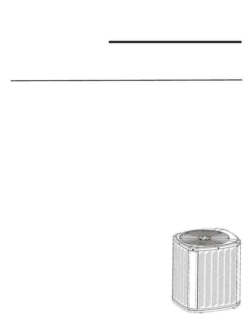
  9. Trane 4TWR2036A1000AA User manual

Trane 4TWR2036A1000AA User manual

HAZARDOUS VOLTAGE - DISCONNECT POWER BEFORE SERVICING
WARNING:
IMPORTANT — This document contains a wiring diagram, a parts list, and service information.This is customer property
and is to remain with this unit. Please return to service information pack upon completion of work.
Service Facts
4TWR2036-SF-1
Split System
Heat Pump
4TWR2036A1000AA
E - SPLIT HEAT
PUMP
Page E-757-000
P.I. 10/01
© 2001 American Standard Inc. All Rights Reserved
NOTICE: Since The Trane Company has a policy of continuous product and product data improvement,
it reserves the right to change design and specifications without notice.
▲CAUTION
!
UNIT CONTAINS R-410A REFRIGERANT!
R-410A OPERATING PRESSURE EXCEEDS THE
LIMIT OF R-22. PROPER SERVICE EQUIPMENT IS
REQUIRED. FAILURE TO USE PROPER SERVICE
TOOLS MAY RESULT IN EQUIPMENT DAMAGE OR
PERSONAL INJURY.
SERVICE
USE ONLY R-410A REFRIGERANT AND
APPROVED POE COMPRESSOR OIL.
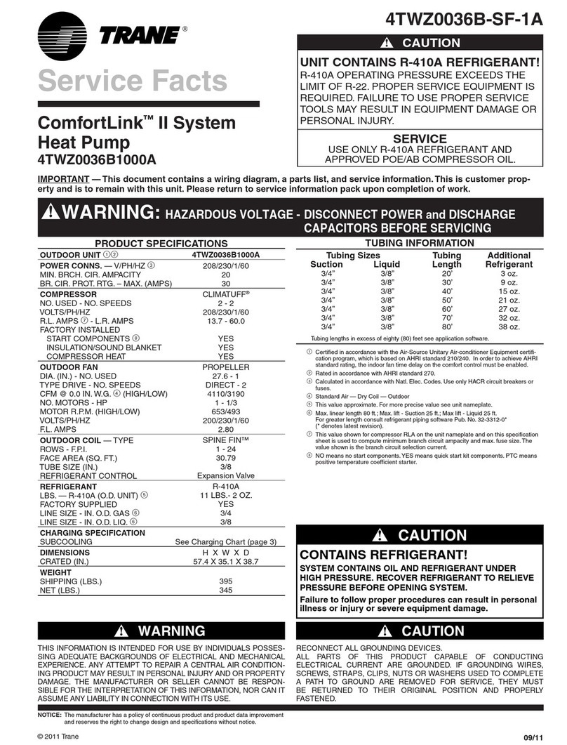
PRODUCT SPECIFICATIONS
OUTDOOR UNIT 12 4TWR2036A1000AA
POWER CONNS. — V/PH/HZ 3208/230/1/60
MIN. BRCH. CIR. AMPACITY 21
BR. CIR. MAX. (AMPS) 35
PROT. RTG. }MIN. (AMPS) 30
COMPRESSOR CLIMATUFF®- SCROLL
NO. USED - NO. SPEEDS 1 - 1
VOLTS/PH/HZ 208/230/1/60
R.L. AMPS 7- L.R. AMPS 15.4 - 83
FACTORY INSTALLED
START COMPONENTS 8NO
INSULATION/SOUND BLANKET YES
COMPRESSOR HEAT NO
OUTDOOR FAN PROPELLER
DIA. (IN.) - NO. USED 23 - 1
TYPE DRIVE - NO. SPEEDS DIRECT - 1
CFM @ 0.0 IN. W.G. 43300
NO. MOTORS - HP 1 - 1/6
MOTOR SPEED R.P.M. 825
VOLTS/PH/HZ 200/230/1/60
F.L. AMPS 1.4
OUTDOOR COIL — TYPE SPINE FIN™
ROWS - F.P.I. 1 - 24
FACE AREA (SQ. FT.) 23.70
TUBE SIZE (IN.) 5/16
REFRIGERANT CONTROL EXPANSION VALVE
REFRIGERANT
LBS. — R-410A (O.D. UNIT) 56 LBS. - 8 OZ.
FACTORY SUPPLIED YES
LINE SIZE - IN. O.D. GAS 63/4
LINE SIZE - IN. O.D. LIQ. 63/8
FCCV
RESTRICTOR ORIFICE SIZE .063
DIMENSIONS H X W X D
CRATED (IN.) 46 x 30.1 x 33.8
WEIGHT
SHIPPING (LBS.) 257
NET (LBS.) 227
1Certified in accordance with the Air-Source Unitary Heat Pump Equipment
certification program, which is based on A.R.I. standard 210/240.
2Rated in accordance with A.R.I. standard 270.
3Calculated in accordance with Natl. Elec. Codes. Only use HACR circuit breakers
or fuses.
4Standard Air -- Dry Coil -- Outdoor
5This value approximate. For more precise value see unit nameplate.
6Max. linear length 60 ft.; Max. lift - Suction 60 ft.; Max lift - Liquid 60 ft.
For greater length consult refrigerant piping software Pub. No. 32-3312-01.
7This value shown for compressor RLA on the unit nameplate and on this
specification sheet is used to compute minimum branch circuit ampacity and
max. fuse size. The value shown is the branch circuit selection current.
8No means no start components. Yes means quick start kit components.
PTC means positive temperature coefficient starter.
TUBING INFORMATION
Tubing Sizes Tubing Additional
Suction Liquid Length Refrigerant
Tubing lengths in excess of sixty (60) feet see application software.
20'
30'
40'
50'
60'
3/4"
3/4"
3/4"
3/4"
3/4"
3/8"
3/8"
3/8"
3/8"
3/8"
3 oz.
9 oz.
15 oz.
21 oz.
27 oz.
CONTAINS REFRIGERANT!
SYSTEM CONTAINS OIL AND REFRIGERANT UNDER
HIGH PRESSURE. RECOVER REFRIGERANT TO RELIEVE
PRESSURE BEFORE OPENING SYSTEM.
Failure to follow proper procedures can result in personal
illness or injury or severe equipment damage.
▲CAUTION
!
▲WARNING
!
THIS INFORMATION IS INTENDED FOR USE BY INDIVIDUALS POSSES-
SING ADEQUATE BACKGROUNDS OF ELECTRICAL AND MECHANICAL
EXPERIENCE. ANY ATTEMPT TO REPAIR A CENTRAL AIR CONDITION-
ING PRODUCT MAY RESULT IN PERSONAL INJURY AND OR
PROPERTY DAMAGE. THE MANUFACTURER OR SELLER CANNOT BE
RESPONSIBLE FOR THE INTERPRETATION OF THIS INFORMATION,
NOR CAN IT ASSUME ANY LIABILITY IN CONNECTION WITH ITS USE.
▲CAUTION
!
RECONNECT ALL GROUNDING DEVICES.
ALL PARTS OF THIS PRODUCT CAPABLE OF CONDUCTING
ELECTRICAL CURRENT ARE GROUNDED. IF GROUNDING
WIRES, SCREWS, STRAPS, CLIPS, NUTS OR WASHERS
USED TO COMPLETE A PATH TO GROUND ARE REMOVED
FOR SERVICE, THEY MUST BE RETURNED TO THEIR
ORIGINAL POSITION AND PROPERLY FASTENED.
HOT SURFACE!
DO NOT TOUCH TOP OF COMPRESSOR.
May cause minor to severe burning.
▲CAUTION
!
70
75
80
85
90
95
SUPERHEAT ˚F
OUTDOOR TEM
50
45
40
35
30
25
20
15
10
5
55 60 65 70 75 80
EXAMPLE: SUC
WHICH GIVES A
OD TEMP=90˚F➀
INTERSECTION
12˚F SUPERHE
ADD CHARGE T
CHART BASED ON 400 CFM/T
50% RELATIVE HUMIDITY, USE ON S
SUPERHEAT CHA
INDOOR
DRY BULB
TEMPERATURE ˚F
LIMIT LINE
Measure suction pressure, suction temperature at O
table what superheat should be for the ID & OD tem
operating superheat with stabilized running conditio
If operating superheat is:
●
within 5˚ chart value charge is OK
●
●
more that 5˚ above chart value add refrigerant
●
2
4
4TWR2036A1000AA
From Dwg. 21D152756 Rev. 1
REFRIGERANT CIRCUIT
SCHEMATIC DIAGRAM
T
DOOR TEMPERATURE ˚F
0
75 80 85 90 95 100 105 110 115
EXAMPLE: SUCTION PRESSURE=65#. SUCTION TEMP=70˚F
WHICH GIVES AN ACTUAL SUPERHEAT OF 32˚F.
OD TEMP=90˚F➀ID TEMP=80˚F➁
INTERSECTION OF ID AND OD TEMPS➂OCCUR ON THE
12˚F SUPERHEAT LINE➃.
ADD CHARGE TO OBTAIN 12˚SUPERHEAT.
E
D ON 400 CFM/TON INDOOR AIRFLOW AND
M
IDITY, USE ON SYSTEMS THAT COOL WITH FCCV
R
HEAT CHARGING CHART
LIMIT LINE
t
ion temperature at OD quick attach, ID & OD temps. Determine from
for the ID & OD temp. Example indicates 12˚superheat. Determine
z
ed running conditions.
s
OK
●
more than 5˚below chart value remove refrigerant
e
add refrigerant
●
if below 5˚limit line, do not add refrigerant
From Dwg. 21C141108 Rev. 0
1
3
Dwg. No. 4TWR2036-SF-1 Page E-757-000
WIRING DIAGRAM
A150999P05 REV.0
LOWER CURVE
MIDDLE CURVE
UPPER CURVE
2010 3025 40 8060
60
50
40
30
25
20
15
10
0
REFRIGERANT
LINE LIFT
(FEET)
TOTAL REFRIGERANT LINE LENGTH (FEET)
CHARGING CURVE SELECTION CHART
TXV REFRIGERANT CHARGING CURVE
For charging outdoor units with R-410A refrigerant at above 65˚F
outdoor temperature in cooling mode and with indoor TXV.
LIQUID PRESSURE (PSIG.)
130120110100908070
600
550
500
450
400
350
300
250
200
LIQUID TEMPERATURE (˚F.)
ADD REFRIGERANT
REMOVE REFRIGERANT
1.
2.
3.
4.
5.
6.
Measure Liquid Line Temperature and
Refrigerant Pressure at service valves.
Determine total refrigerant pipe length
and height (lift) if indoor section is above
the condenser. Plot the intersection of
the two points on the Curve Selection
Chart to determine which curve to use.
Plot the pressure and temperature on
the TXV Charging Curve.
If the lines cross above the curve remove
refrigerant, if below curve add refrigerant.
Whenever charge is removed
or added, the system must
be operated for a minimum
20 minutes to stabilize before
additional measurements can
be made.
When system is correctly
charged refer to System
Performance Curves to verify
charge and performance.
▲
▲
▲
▲
PRESSURE CURVES FOR 4TWR2036A1000AA
TXC037C4 4TEP3F36A1 4TEP3F36A1
Cooling with FCCV Cooling with Thermal Expansion Valve Heating
DISCHARGE PRESSURE (PSIG)
OUTDOOR TEMPERATURE (Degree F)
SUCTION PRESSURE (PSIG)
OUTDOOR TEMPERATURE (Degree F)
COOLING PERFORMANCE CAN BE CHECKED WHEN THE OUTDOOR TEMP IS ABOVE 65 DEG F.
TO CHECK COOLING PERFORMANCE, SELECT THE PROPER INDOOR CFM, ALLOW PRESSURES TO STABILIZE. MEASURE INDOOR WET BULB
TEMPERATURE, OUTDOOR TEMPERATURE, DISCHARGE AND SUCTION PRESSURES. ON THE PLOTS LOCATE OUTDOOR TEMPERATURE (1);
LOCATE INDOOR WET BULB (2); FIND INTERSECTION OF OD TEMP. & ID W.B. (3); READ DISCHARGE OR SUCTION PRESSURE IN LEFT
COLUMN (4).
EXAMPLE: (1) OUTDOOR TEMP. 82 F.
(2) INDOOR WET BULB 67 F.
(3) AT INTERSECTION ACTUAL:
(4) DISCHARGE PRESSURE @ 1200 CFM IS 330 PSIG DISCHARGE PRESSURE SHOULD BE +/- 10 PSI OF CHART
(5) SUCTION PRESSURE @ 1200 CFM IS 134 PSIG. SUCTION PRESSURE SHOULD BE +/- 3 PSIG OF CHART
INTERCONNECTING LINES
GAS - 3/4" O.D.
LIQUID - 3/8" O.D.
DWG.NO. 4TWR2036A1
100
105
110
115
120
125
130
135
140
145
150
155
160
165
170
40 60 80 100 120
100
105
110
115
120
125
130
135
140
145
150
155
160
165
170
40 60 80 100 120
250
300
350
400
450
500
40 60 80 100 120
250
300
350
400
450
500
40 60 80 100 120
(1)
(1)
(3)
(3)
(5)
(4)
(2)
(2)
INDOOR ENTERING
WET BULB CURVES
TOP TO BOTTOM 71,
67, 63 AND 59 DEG F.
INDOOR ENTERING
WET BULB CURVES
TOP TO BOTTOM 71,
67, 63 AND 59 DEG F.
INDOOR ENTERING
WET BULB CURVES
TOP TO BOTTOM 71,
67, 63 AND 59 DEG F.
INDOOR ENTERING
WET BULB CURVES
TOP TO BOTTOM 71,
67, 63 AND 59 DEG F.
30
40
50
60
70
80
90
100
110
120
130
140
-5 5 152535455565
200
250
300
350
400
450
500
-5 5 152535455565
INDOOR ENTERING
DRY BULB CURVES
TOP TO BOTTOM 80,
70, AND 60 DEG F.
INDOOR ENTERING
DRY BULB CURVES
TOP TO BOTTOM 80,
70, AND 60 DEG F.
TU/DD060R9V3+TXH033A4 1200 0 0 0 12
TU/DD060R9V3+TXH041A4 1200 3 5 0 -11
TU/DD080R9V3+TXH033A4 1125 -1 -2 1 21
TU/DD080R9V3+TXH041A4 1140 2 3 0 -5
TU/DD100R9V5+TXH033A4 1130 -1 -2 1 20
TU/DD100R9V5+TXH041A4 1200 3 5 0 -11
TDY060R9V3+TXH033A4 1080 -2 -4 1 26
TDY060R9V3+TXH041A4 1070 0 1 0 2
TDY080R9V3+TXH033A4 1100 -2 -3 1 24
TDY080R9V3+TXH041A4 1100 1 2 0 -1
TDY100R9V4+TXH033A4 1050 -3 -5 1 30
TDY100R9V4+TXH041A4 1050 0 0 0 5
TUY060R9V3+TXH033A4 1070 -2 -4 1 28
TUY060R9V3+TXH041A4 1025 -1 -1 0 8
TUY080R9V3+TXH033A4 1000 -4 -7 1 38
TUY080R9V3+TXH041A4 1025 -1 -1 0 8
TUY100R9V4+TXH033A4 1050 -3 -5 1 30
TUY100R9V4+TXH041A4 1050 0 0 0 5
TVF030A14 1125 0 0 0 3
TVF036A14 1200 3 5 -1 -17
TWE030C14 949 -9 -14 2 65
TWE036C14 1200 -2 -3 0 15
TWE042C14 1350 3 6 0 -14
TWE048C14 1350 5 9 -1 -29
TXA,TXC030C4,D4 1100 -4 -7 1 45
TXA,TXC031C4,D4 1100 -3 -5 0 14
TXA,TXC035C4,D4 1100 -4 -7 1 45
TXA,TXC036C4,D4 1200 0 0 0 -10
* TXA,TXC037C4 1200 0 0 0 -10
TXA,TXC042C4 1200 1 2 -1 -16
TXA,TXC043C4 1350 3 6 -1 -29
TXA,TXC048C4 1350 5 10 -1 -39
TXA,TXC049C4 1350 5 10 -1 -39
TXA,TXC050C4 1350 5 10 -1 -39
TXH033A4 1125 -1 -2 0 14
TXH041A4 1350 5 9 -1 -29
ALTERNATE INDOOR UNITS
PRESSURE CURVE CORRECTION PSIG
WITH FCCV OR TXV —COOLING——HEATING—
SUCT. HEAD SUCT. HEAD
INDOOR UNIT CFM PRESS PRESS PRESS PRESS
ALTERNATE INDOOR UNITS
PRESSURE CURVE CORRECTION PSIG
WITH THERMAL EXPANSION VALVE —COOLING——HEATING—
SUCT. HEAD SUCT. HEAD
INDOOR UNIT CFM PRESS PRESS PRESS PRESS
4TEE3F31A 1220 0 0 0 13
4TEE3F37A 1160 0 0 0 4
4TEE3F40A 1200 8 4 -1 -39
4TEP3F30A 940 -5 -3 1 51
* 4TEP3F36A 1200 0 0 0 0
4TEP3F42A 1350 6 3 -1 -29
4TEP3F48A 1350 11 6 -2 -59
RXC031S3 1110 0 0 0 0
RXC036S3 1200 5 3 -1 -28
RXC037S3 1200 5 3 -1 -28
RXC054S3 1350 7 4 -1 -45
TDD060R9V3+RXC031S3 1200 2 1 0 -4
TDD060R9V3+RXC036S3 1200 5 3 -1 -23
TDD080R9V3+RXC031S3 1120 0 0 0 4
TDD080R9V3+RXC036S3 1130 3 2 -1 -16
TDD100R9V5+RXC037S3 1180 4 2 -1 -21
TDY060R9V3+RXC031S3 1090 0 0 0 8
TDY060R9V3+RXC036S3 1085 3 1 0 -12
TDY080R9V3+RXC031S3 1050 -1 -1 0 13
TDY080R9V3+RXC036S3 1050 2 1 0 -8
TDY100R9V4+RXC037S3 1050 2 1 0 -8
TUD060R9V3+RXC031S3 1200 2 1 0 -4
TUD060R9V3+RXC036S3 1200 5 3 -1 -23
TUD080R9V3+RXC031S3 1200 2 1 0 -4
TUD080R9V3+RXC036S3 1200 5 3 -1 -23
TUD100R9V5+RXC037S3 1200 5 3 -1 -23
TUY060R9V3+RXC031S3 1050 -1 -1 0 13
TUY060R9V3+RXC036S3 1050 2 1 0 -8
TUY080R9V3+RXC031S3 1040 -1 -1 0 14
TUY080R9V3+RXC036S3 1040 2 1 0 -7
TUY100R9V4+RXC037S3 1060 2 1 0 -9
* BASE INDOOR UNIT(S) CURVES ON 4TWR2036A1
NOTES:
1
For a field installed TXV kit, apply the factor listed with the FCCV model to the TXV curve.
▲

Other Trane Heat Pump manuals

Trane SSC-APG002-EN User guide

Trane

Trane SSC-APG002-EN User guide

Trane 5TTX5018 User manual

Trane

Trane 5TTX5018 User manual

Trane 5TWX5 User manual

Trane

Trane 5TWX5 User manual

Trane WFS-IR 1 Quick start guide

Trane

Trane WFS-IR 1 Quick start guide

Trane Ultra-Low NOx Series Assembly instructions

Trane

Trane Ultra-Low NOx Series Assembly instructions

Trane CAUC-C20 Owner's manual

Trane

Trane CAUC-C20 Owner's manual

Trane RAUS 040 Owner's manual

Trane

Trane RAUS 040 Owner's manual

Trane 4TWR3 Installation instructions

Trane

Trane 4TWR3 Installation instructions

Trane ComfortLink 4TWZ0024A1000A User manual

Trane

Trane ComfortLink 4TWZ0024A1000A User manual

Trane SSC-APG002-EN User guide

Trane

Trane SSC-APG002-EN User guide

Trane XL14i User manual

Trane

Trane XL14i User manual

Trane 13.4 SEER2 J4PH4 Series User manual

Trane

Trane 13.4 SEER2 J4PH4 Series User manual

Trane RAUS 040 Owner's manual

Trane

Trane RAUS 040 Owner's manual

Trane 4TWR6 Assembly instructions

Trane

Trane 4TWR6 Assembly instructions

Trane 4TTR4018L Assembly instructions

Trane

Trane 4TTR4018L Assembly instructions

Trane 4WCY4024 Operation manual

Trane

Trane 4WCY4024 Operation manual

Trane 2TWZ9 Assembly instructions

Trane

Trane 2TWZ9 Assembly instructions

Trane Axiom EXW Series Installation and operating instructions

Trane

Trane Axiom EXW Series Installation and operating instructions

Trane Precedent WSC User manual

Trane

Trane Precedent WSC User manual

Trane XL Series Weathertron Installation instructions

Trane

Trane XL Series Weathertron Installation instructions

Trane 2TTA0030AD000A Assembly instructions

Trane

Trane 2TTA0030AD000A Assembly instructions

Trane 4WCC4024E1000A User manual

Trane

Trane 4WCC4024E1000A User manual

Trane WSC036A Owner's manual

Trane

Trane WSC036A Owner's manual

Trane GETB User manual

Trane

Trane GETB User manual

Popular Heat Pump manuals by other brands

Daikin Altherma EAVH16S23DA6V Installer's reference guide

Daikin

Daikin Altherma EAVH16S23DA6V Installer's reference guide

Danfoss OPTYMA Plus Series manual

Danfoss

Danfoss OPTYMA Plus Series manual

Daikin UWL-B5 Series Catalogue/Engineering Data

Daikin

Daikin UWL-B5 Series Catalogue/Engineering Data

Bard Q24H2-A installation instructions

Bard

Bard Q24H2-A installation instructions

Baxi Geoflo Operation, installation & maintenance instructions

Baxi

Baxi Geoflo Operation, installation & maintenance instructions

T.I.P. STEAM 25000 Translation of original operating instructions

T.I.P.

T.I.P. STEAM 25000 Translation of original operating instructions

LG Therma V 5BPM5-01B Product data book

LG

LG Therma V 5BPM5-01B Product data book

Bard QH242D installation instructions

Bard

Bard QH242D installation instructions

Hitachi RAS-8FSXNS2E Installation & operation manual

Hitachi

Hitachi RAS-8FSXNS2E Installation & operation manual

Carrier 38BQ Installation, Start-Up and Service Instructions

Carrier

Carrier 38BQ Installation, Start-Up and Service Instructions

Bryant 548J*D Series installation instructions

Bryant

Bryant 548J*D Series installation instructions

Daikin EWAT016CZN-A1 Installation, maintenance and operation manual

Daikin

Daikin EWAT016CZN-A1 Installation, maintenance and operation manual

Carrier 25HCA installation instructions

Carrier

Carrier 25HCA installation instructions

Daikin FWE03D Series installation manual

Daikin

Daikin FWE03D Series installation manual

TTI FABRICATION ECOLO 50 Installation and operation manual

TTI FABRICATION

TTI FABRICATION ECOLO 50 Installation and operation manual

WarmFlow G Series manual

WarmFlow

WarmFlow G Series manual

WarmPool OPTIMUS E7 quick start

WarmPool

WarmPool OPTIMUS E7 quick start

Airrex AHSC-18 user manual

Airrex

Airrex AHSC-18 user manual

manuals.online logo
manuals.online logoBrands
  • About & Mission
  • Contact us
  • Privacy Policy
  • Terms and Conditions

Copyright 2025 Manuals.Online. All Rights Reserved.