American LED-gible AF-2720-912 User manual

Model AF-2720-912
The Production Cycle Timer
Owners Manual
2”, 4 Digit, 2 Line, Goal / Actual Marquee with 4x3 Matrix Key ad
Firmware: PP-2110-543D Hardware: AB-2486-224D
Manual PB-2149-610
Revision F
A ril 6, 2016
American LED-gi le® Inc.
1776 Lone Eagle St.
Columbus, OH 43228
(614) 851-1100 Phone
(614) 851-1121 Fax
www.ledgible.com www
ledgible@ledgible.com e-mail


Ta le of Contents
1.0 Getting Started........................................................................................................................1
1.1 Product Descri tion............................................................................................................1
1.2 Un acking the Unit.............................................................................................................2
1.3 Mounting the PCT Enclosure.............................................................................................2
1.4 Introduction to the PCT Circuit Board................................................................................3
1.4.1 120VAC Power Connectors........................................................................................5
1.4.2 Logic In ut Connectors...............................................................................................6
1.4.3 Serial Port Connectors................................................................................................7
1.4.4 Relay Out ut Connectors............................................................................................8
1.4.5 Status Indicator Lam s...............................................................................................9
1.4.6 Configuration Di -Switches......................................................................................10
1.4.7 Selecting the PCT Timing Mode...............................................................................11
1.4.8 Selecting Time Minus or Time Plus Stack light Mode..............................................12
1.5 120VAC Power Installation..............................................................................................13
1.6 Logic In ut Installation.....................................................................................................14
1.7 Serial Communications Installation..................................................................................16
1.8 Pro er use of the PCT Key ad........................................................................................16
2.0 Basic O eration....................................................................................................................17
2.1 Adjusting Register Values................................................................................................17
2.2 Basic O eration Exam le.................................................................................................18
3.0 In Case of Difficulties............................................................................................................19
3.1 Contacting American LED-gible® Inc..............................................................................19
4.0 Product S ecifications..........................................................................................................20
5.0 Limited Warranty..................................................................................................................21
6.0 ASCII Chart...........................................................................................................................22
7.0 Connection Labels................................................................................................................24


The Production Cycle Timer
Owners Manual
1.0 Getting Started
Thank you for your urchase of an AMERICAN LED-gible® roduct. We take ride in the equi ment we build, and
we a reciate your su ort. We will do everything we can to kee you ha y with your urchase for many years
to come. Please review this manual carefully, and if you have any questions, call, e-mail, or fax us and we will be
glad to hel you. American LED-gible su ort can be reached at:
1.1 Product Description
The roduction cycle timer (PCT) is a s ecial ur ose numeric marquee designed to ace the roduction rate of a
manual rocess with long cycle times. The PCT GOAL line dis lays the o erator entered goal cycle time. This
field does not change unless adjusted by the o erator via the key ad. The PCT ACTUAL line starts at the
rogramed goal cycle time, and times down to zero. Once zero has been reached, the ACTUAL line begins to
flash and time u to dis lay the amount of cycle time overage. The PCT can be configured to time in tenths of
seconds, seconds, tenths of minutes, minutes, tenths of hours, or hours. See section 1.4.7 for directions on how
to select the timing mode.
If the PCT has the o tional RED / YLW stack light installed, then PCT o erator may s ecify a yellow time length,
and a red time length in addition to the goal cycle time. Initially when the PCT is reset, the stack light starts out off.
After some time has ela sed the stack light will switch from off to yellow. Then after the rogrammed yellow time
has ela sed the stack light will switch from yellow to red. Then after the rogrammed red time has ela sed the
stack light will switch from red to flashing red.
By default, the stack light switches from off to yellow when the actual time remaining reaches zero (Time Minus
Mode). However the PCT can be configured so that the stack light transitions from red to flashing red when the
actual time remaining reaches zero (Time Plus Mode). See section 1.4.8 for directions on how to select time
minus mode or time lus mode.
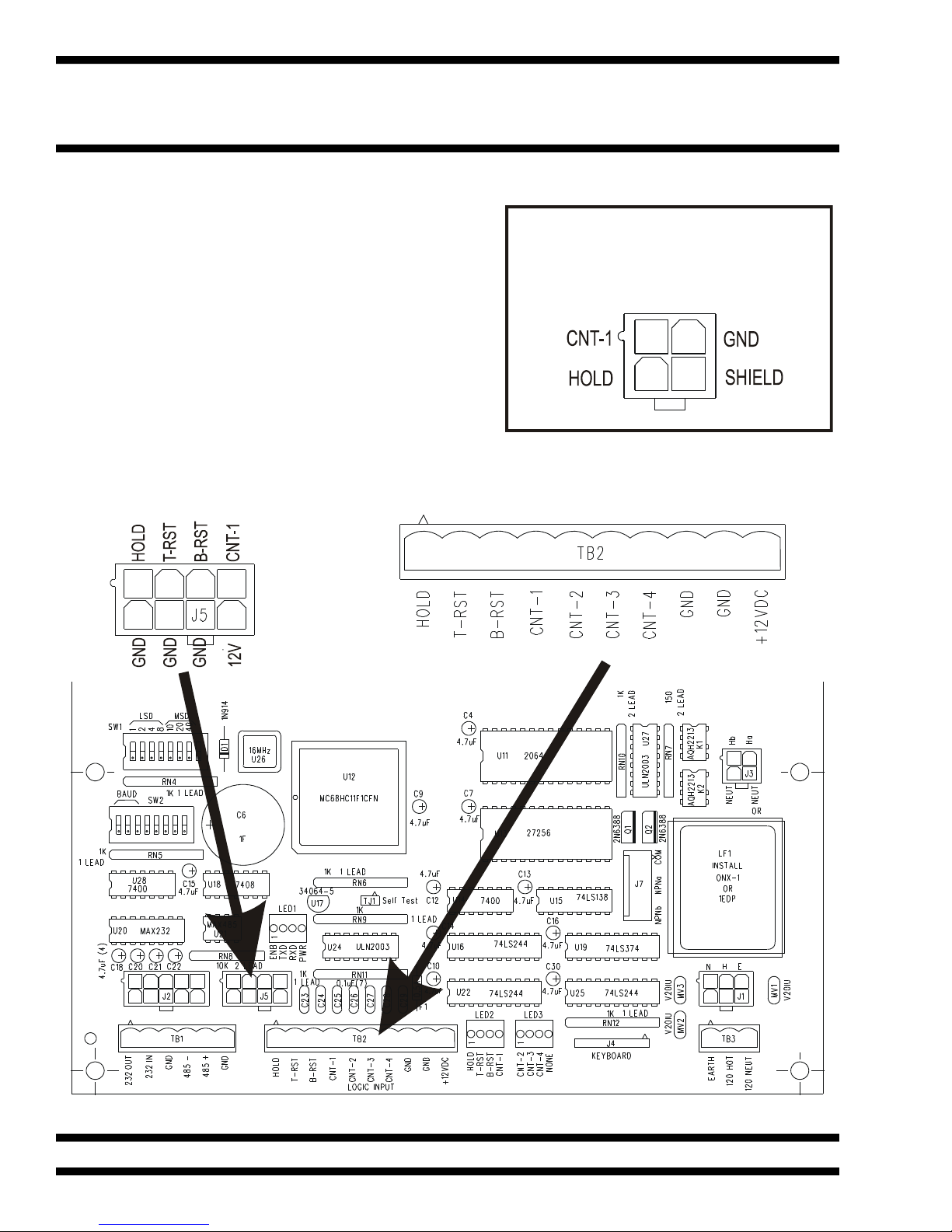
The PCT has seven logic in uts (HOLD, T-RST, B-RST, CNT-1, CNT-2, CNT-3, CNT-4). The HOLD in ut auses
the PCT timer for as long as the in ut is activated. Both the T-RST and the B-RST reset in uts reset the actual
timer to the rogrammed goal cycle time. All four CNT-x count in uts also reset the actual timer to the
rogrammed goal cycle time. During breaks activate the HOLD in ut to ause the actual timer. At the start of
each cycle, ulse one of the reset or count in uts to reset the actual timer back to the rogrammed goal cycle
time.
A 1 Farad Su er-Ca backs u the CCTs memory. The Su er-Ca allows the PCT to retain o erational values for
five days without ower. Unlike batteries, Su er-Ca s do not require s ecial recharge circuitry and have an
ex ected life s an in excess of 10 years.
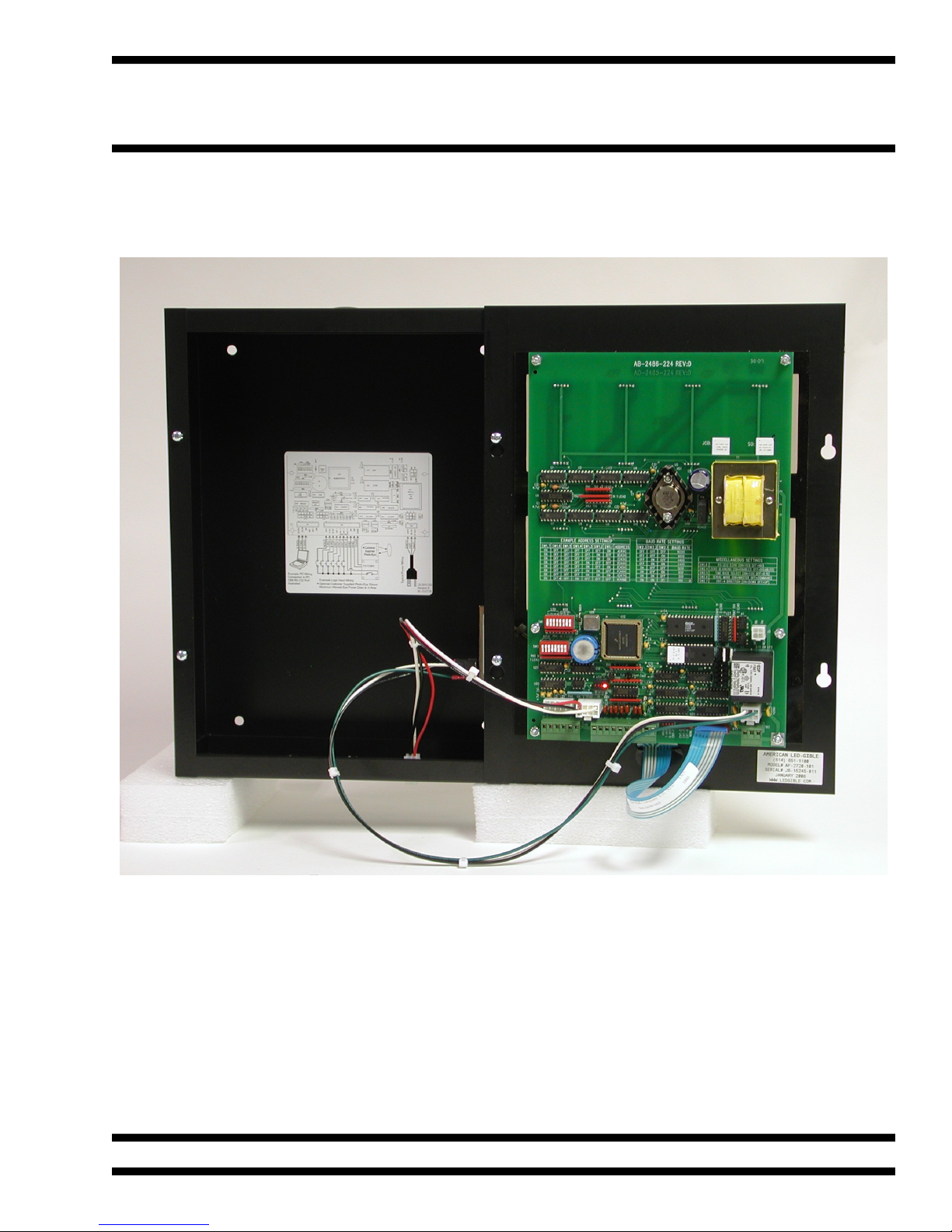
The PCT is enclosed in a NEMA-1 black satin ainted 16-gauge steel enclosure with a 1/8” thick, acrylic dis lay
lens. The enclosure is designed to be mounted to a wall by four holes in the back of the enclosure.
Page 1
American LED-gi le® Inc.
1776 Lone Eagle St.
Columbus, OH 43228
(614) 851-1100 Phone
(614) 851-1121 Fax
www.ledgible.com www
su ort@ledgible.com e-mail

The Cycle Timer
Owners Manual
1.2 Unpacking the Unit
Every PCT is carefully tested, both mechanically and electrically, before shi ment. Ins ect the marquee for
damage, which may have occurred in transit. If there is evidence of damage, file a claim with the shi er and
notify American LED-gible.® Save the shi ing materials for ins ection.
If there are no signs of damage, carefully remove the PCT from the shi ing carton. Then mount, hang, or set the
PCT in a location where the unit is readily visible.
1.3 Mounting the PCT Enclosure
The PCT is designed to be mounted to a wall by four screw holes in the back of the enclosure. When choosing
the location to mount the PCT, kee in mind the o erator will need access to the key ad on the front of the unit.
The PCT should be moved to its o erating osition and mounted to the wall using the four holes in the back of the
enclosure. A drawing of the box ortion of the enclosure is shown below.
Page 2
Mounting
Holes
Mounting
Holes

The Production Cycle Timer
Owners Manual
1.4 Introduction to the PCT Circuit Board
A convenient way to work on the PCT is to loosen the front anel, fli it over, and then tem orarily su ort the font
anel by hanging it on two of the box screws as shown in the icture below.
Page 3

The Cycle Timer
Owners Manual
A diagram of the PCT circuit board is shown below. Take note of the indicated connectors, switches, and indicator
lam s. Other sections of this manual will direct the customer to wire to these connectors, set di switch o tions,
and observe indicator lam behavior. If you are having difficulty locating a referenced connector, switch, or lam ,
referring back to this age may hel you locate it.
Most of the electrical connections to the PCT are available on both a customer connector, and a factory connector.
Customer connectors rovide sim le screw terminal termination for 22 to 16 gage wires for use by the customer.
Factory connectors rovide crim ed in termination for 20 gage wires. The rimary ur ose of the factory
connectors is to rovide American LED-gible with an alternate location to terminate factory installed wiring that will
not consume customer screw terminals.
Indicator lam s rovide real time feedback on the status of the PCT to aid debugging roblems. The ower
indicator lam illuminates when ower is a lied to the PCT. The TXD, RXD, and ENB lights blink during serial
communications, and the remaining lam s illuminate when the associated logic in ut is activated.
Page 4
120VAC Relay Out uts Connector
Firmware EPROM in Socket
Configuration Di Switch Blocks
DC Sink Relay Out uts Connector
Factory 120VAC Power Connector
Customer 120VAC Power Connector
Key ad Connector
Exam le Di Switch Settings
Serial Port Status Indicator Lam s
Factory Serial Port Connector
Customer Serial Port Connector
Factory Logic In ut Connector
Customer Logic In ut Connector
In uts Status
Indicator Lam s

The Production Cycle Timer
Owners Manual
1.4.1 120VAC Power Connectors
The PCT requires 120VAC at ½ Am current draw to o erate (without the o tional stack light installed). However,
If custom devices are connected to the silicon relay out uts, the maximum current draw could be as high as 1½
Am s. If you have the o tional stack light, assume a ower draw of 120VAC at 1 ½ Am . The PCT can o erate
from either 60Hz or 50Hz ower.
If your unit was urchased with the ower cord o tion, the factory will have already installed an industry standard
three rong line cord, and connected it to the factory 120VAC ower connector. If this is the case, do not connect
any wires to the customer 120VAC ower connector.
Page 5
Customer 120VAC
Power Connector
Factory 120VAC
Power Connector

The Cycle Timer
Owners Manual
1.4.2 Logic Input Connectors
The PCT has seven digital logic in uts. Each in ut is activated
by connecting the in ut terminal to the GND terminal with a dry
contact or an NPN (current sinking) out ut.
If your PCT was urchased with the o tional logic in ut
extension cable, the factory will have already installed wiring
that rovides the CNT-1 and HOLD in uts on a six foot
extension cable terminated in a four in Molex Minifit Jr
connector as diagrammed to the right.
Even if the logic in ut extension cable is installed, it is still
ermissible to use the customer logic in ut connector to
connect other devices to the PCT. The CNT-1 wire of the
extension cable is connected in arallel with the CNT-1 screw
terminal on the customer logic in ut connector.
Page 6
O tional Logic In ut
Extension Cable Pinout
Customer Logic
In ut Connector
Factory Logic
In ut Connector

The Production Cycle Timer
Owners Manual
1.4.3 Serial Port Connectors
The PCT has one serial communications channel that can be configured for RS-232 or RS-485 communications.
Se arate wiring terminals are rovided for RS-232 and RS-485 wiring, on both the customer and the factory
connectors.
Page 7
Customer Serial
Port Connector
Factory Serial
Port Connector

The Cycle Timer
Owners Manual
1.4.4 Relay Output Connectors
The PCT rovides two 120VAC silicon relay out uts or two DC Sink (NPN) relay out uts. These connectors are
not intended to be used by the customer. They are used by ALI to control various o tional PCT add ons, such as
the red / yellow stack light.
When the PCT is ordered with the o tional red / yellow stack light, the Ha 120VAC relay out ut controls the red
light, and the Hb 120VAC relay out ut controls the yellow light.
The DC Sink relay out uts are reserved by ALI for future feature ex ansions to the PCT.
Note: Do not connect any wiring to the 120VAC or DC Sink relay output connectors unless directed to do
so y American Led-gi le Inc.
Page 8
Factory 120VAC
Silicon Relay Out uts
Factory DC Sink
NPN Relay Out uts

The Production Cycle Timer
Owners Manual
1.4.5 Status Indicator Lamps
The PCT has several indicator lam s that are quite hel ful for debugging wiring roblems.
To debug ower wiring, a ly 120VAC ower to the PCT and then make sure the PWR indicator is illuminated. If
it does not, then the 120VAC ower wiring is robably incorrect.
To debug logic in ut wiring, activate the switch or sensor while observing the LED2 and LED3 indicator lam s.
The indicator corres onding to the activated in ut should illuminate. If it does not, try activating the in ut with a
few inches of wire. When you connect the in ut screw terminal to the ground screw terminal, the in ut should
activate, and the indicator lam should illuminate.
To debug serial communications wiring, observe the ENB, TXD, and RXD lam s while attem ting to communicate
with the PCT. The RXD lam should illuminate if the PCT is receiving commands. The TXD lam should
illuminate when the PCT is res onding.
Page 9
Logic In ut Status
Indicator Lam s
Serial Port / Power
Status Indicator Lam s

The Cycle Timer
Owners Manual
1.4.6 Configuration Dip-Switches
The configuration di switch blocks are used to configure semi- ermanent PCT settings. These are settings that
are likely to be decided u on when the PCT is first installed, and then never changed. PCT settings that are likely
to change from week to week are set using the key ad on the front of the unit.
As of revision D of the PP-2110-543 firmware, the only di -switches with significant im act on the o eration of the
PCT are Switches 4 and 5 on the SW2 switch block.
Page 10
SW2 Configuration
Switch Block
SW1 Configuration
Switch Block
Shown with switches
1, 7, and 8 ON
Shown with switches
1, 7, and 8 ON

The Production Cycle Timer
Owners Manual
1.4.7 Selecting the PCT Timing Mode
The PCT can be configured to time in tenths of seconds, seconds, tenths of minutes, minutes, tenths of hours, or
hours. The timing mode is selected by three switches on SW2.
SW2.8 SW2.7 SW2.6 Timing Mode
OFF OFF OFF XXX.X Seconds
OFF OFF ON XXXX Seconds
OFF ON OFF XXX.X Minutes
OFF ON ON XXXX Minutes
ON OFF OFF XXX.X Hours
ON OFF ON XXXX Minutes
Page 11
Shown with switches
1, 7, and 8 ON

The Cycle Timer
Owners Manual
1.4.8 Selecting Time Minus or Time Plus Stack light Mode
If you don't have the o tional Red / Yellow stack light, this switch setting has no effect on your unit.
By default, the factory sets switch SW2.5 to the OPEN or OFF osition which selects Time Minus stack light
mode.
In the Time Minus mode, the stack light remains off until the actual time remaining reaches zero. Then the stack
light will switch from off to yellow, the actual time remaining will begin flashing and timing u the overage. When
the overage time exceeds the rogrammed yellow time, the stack light will switch from yellow to red. When the
overage exceeds the rogrammed yellow time lus the rogrammed red time the stack light will switch from red to
flashing red.
In the Time Plus mode, the stack light remains off until the actual time remaining reaches the rogrammed yellow
time lus the rogrammed red time. Then the stack light switches from off to yellow. When the actual time
remaining reaches the rogrammed red time, the stack light will switch from yellow to red. When the actual time
remaining reaches zero, the stack light will switch from red to flashing red, and the actual dis lay will begin
flashing and timing u the overage.
To set the PCT to Time Plus Mode, turn switch SW2.5 ON. To return the PCT to Time Minus mode, turn SW2.5
back OFF.
Page 12

The Production Cycle Timer
Owners Manual
1.5 120VAC Power Installation
If your PCT was ordered with the o tional American 120VAC line cord o tion, you will sim ly need to rovide a
standard 120VAC du lex near the PCT. However if your unit does not have the o tional line cord, you will need to
connect 120VAC ower to screw terminals inside the PCT as shown below.
Connect the ower wiring to the customer 120VAC ower screw terminal connector on the PCT circuit board.
Power wires should be American Wire Gauge #16 with a 600 volt insulation rating. The PCT requires 120VAC
ower at less than ½ Am of current. However, if equi ment is connected to the 120VAC out ut relays (such as a
stack light), the PCT ower draw can be as great as 1 ½ Am s. Both 60Hz and 50Hz line frequencies are
acce table.
Page 13
Ty ical Power Wiring

The Cycle Timer
Owners Manual
1.6 Logic Input Installation
If your PCT was ordered with the o tional count ush button kit, or the o tional hoto-eye kit, some / all of the logic
wiring you need may have already been com leted by the factory. However you may still wish to review this
section for information on how the PCT logic in uts are o erated.
The PCT's logic in uts are designed to be activated by connecting an in ut screw terminal (HOLD, T-RST,B-RST,
or CNT) to a ground screw terminal (GND). Ty ically this is accom lished with a ush button switch, whisker
switch, or mechanical relay contact. However it can also be done with an NPN or CURRENT SINKING hoto-eye,
roximity sensor, or solid state relay.
The digital logic in uts are sam led once every 10mS, and then rocessed by a sim le software debounce
algorithm. Transient conditions lasting less than 30mS are rejected as noise. Due to this filtering, the maximum
allowed count rate is 10Hz, with a 50% duty cycle waveform (50mS On Time, 50mS Off Time), and the minimum
width of a reset ulse is 50mS.
If your PCT was urchased with the o tional logic in ut extension cable, the factory will have already installed
wiring that rovides the CNT-1 and HOLD in uts on a six foot extension cable terminated in a four in Molex
Minifit Jr connector as diagrammed below.
Even if the logic in ut extension cable is installed, it is still ermissible to use the customer logic in ut connector to
connect other devices to the PCT. The CNT-1 wire of the extension cable is connected in arallel with the CNT-1
screw terminal on the customer logic in ut connector.
Page 14
1K 1K
+12VDC +12VDC
0.1uF 0.1uF
2003 2003INPUT INPUT
GND GND
PPT Logic In ut PPT Logic In utCustomer Wiring Customer Wiring
Push Button
Switch NPN
Transister
O tional Logic In ut
Extension Cable Pinout

The Production Cycle Timer
Owners Manual
If you are using a 12VDC hoto-eye or roximity sensor, the PCT can su ly u to ½ am of ower to the sensor.
Be careful when connecting the +12VDC out ut to your sensor. If the sensor draws too much current, the fuse
(F1) soldered to the PCT board will blow to rotect the PCT ower su ly.
Exam le logic in ut wiring is shown in the diagram below. Kee in mind, that for your a lication, you may chose
to not use some of the logic in uts. The minimum requirement is one switch or sensor that is used to activate one
of the count in uts each time a unit of roduction is com leted. All of the other in uts (HOLD, T-RST, B-RST)
functionality can be re licated by ressing buttons on the PCT key ad.
Connecting the HOLD in ut to GND auses the ACTUAL timer. Connecting the T-RST in ut to GND resets the
actual timer to the rogrammed goal cycle time. Connecting the B-RST in ut to GND resets the ACTUAL timer to
the rogrammed goal cycle time. Connecting any of the CNT in uts to GND resets the actual timer to the
rogrammed goal cycle time.
Page 15
Exam le Logic In ut Wiring
O tional Customer Su lied Photo-Eye Shown
Maximum Allowed Eye Power Draw is ½ Am
*
*
HOLD
T-RST
B-RST
CNT-1
CNT-2
CNT-3
CNT-4
GND
GND
12VDC

The Cycle Timer
Owners Manual
1.7 Serial Communications Installation
As of May 12 2014, the PCT firmware (PP-2110-543B) does not make use the PCT serial ort hardware. Future
revisions of the PCT firmware may activate the serial ort for use as a su ervisor interface, or ossibly to transmit
data to slave dis lays, but at this time the serial ort is not used.
1.8 Proper use of the PCT Keypad
The PCT key ad is designed for o eration by a human finger, and when ro erly used, each key is rated for over
1,000,000 o erations. However, if a hard object, such as a en, encil, or wood / steel rod is used to o erate the
key ad, it will severely decrease its o erational lifes an. We have observed key ads failing in as little as three
months when abused. Key ad failures due to abuse are not covered under the 1 year warranty.
The hoto below shows the ty ical damage cased by using a hard object such as a encil to de ress the [RUN]
key. The olycarbonate overlay has warn through ex osing the 12oz tri-dome. Additionally the tri-dome has
colla sed, causing the key to “stick on”. When this ha ens, all of the keys on the key ad become non-functional.
To re air the PCT, the key ad must be ealed off of the PCT front anel and re laced.
Re lacement key ads may be urchased and shi ed to your factory for you to install. Contact American LED-
gible and order art number, KB-2659-003 which has a list rice of $25 each.
Page 16
Table of contents