EMKO EZM-4450 User manual

EZM-4450 48x48 1/16 DIN Programmable Timer & Counter
- 6 digits Process (PV) and 6 digits Set (SV) Value Display
- Operation with 2 Set Value
- Reset , Pause and ChA-ChB Counting Inputs
- Configurable Counter / “Totalizer Counter”, Batch Counter ,
Timer, Chronometer , Frequencymeter and Tachometer Functions
- Programmable Time Bases for Timer and Chronometer (Second ,
Minute , Hour )
- Operation with Automatic and Manual Reset
- Output Module System
- NPN/PNP Type Operation
- INC , DEC , INC / INC , INC / DEC , UP / DOWN , x1 / x2 / x4
Counting with Phase Shifting Property in Counter Function
- Multiplication Coefficient and Decimal Point Position
- Different Alarm Alternatives in Frequencymeter and Cycle
Measuring Functions
- Absolute or Offset Operation in Counter Function
- RS-232 (standard) or RS-485 (optional) Serial Communication
with Modbus ASCII or RTU Protocol
EZM-4450 48 x 48 1/16 DIN
Universal Input Programmable Timer &
Counter with Output Module System
Instruction Manual. ENG EZM-4450 02 V14 07/14

ABOUT INSTRUCTION MANUAL
2
Instruction manual of EZM-4450 Programmable Timer&Counter consists of two main
sections. Explanation of these sections are below. Also, there are other sections which include
order information and technical specifications of the device. All titles and page numbers in
instruction manual are in “CONTENTS” section. User can reach to any title with section number.
Installation:
In this section, physical dimensions of the device, panel mounting, electrical wiring,
module mounting in the device, physical and electrical installation of the device to the system are
explained.
Operation and Parameters:
In this section, user interface of the device, how to access to the parameters, description
of parameters are explained.
Also in these sections, there are warnings to prevent serious injury while doing the
physical and electrical mounting or using the device.
Explanation of the symbols which are used in these sections are given below.
a
c
i
This symbol is used to determine the dangerous situations as a result of an electric
shock. User must pay attention to these warnings definitely.
This symbol is used for safety warnings. User must pay attention to these
warnings.
This symbol is used to determine the important notes about functions and usage of
the device.

1.PREFACE..................................................................................................................
1.1 GENERAL SPECIFICATIONS
1.2 ORDERING INFORMATION
1.3 WARRANTY
1.4 MAINTENANCE
2.INSTALLATION.........................................................................................................
2.1 GENERAL DESCRIPTION
2.2 DIMENSIONS
2.3 PANEL CUT-OUT
2.4 ENVIRONMENTAL RATINGS
2.5 PANEL MOUNTING
2.6 INSTALLATION FIXING CLAMP
2.7 REMOVING FROM THE PANEL
2.8 SELECTION OF OPERATION FUNCTION AND INPUT TYPE WITH DIP
SWITCH
3.ELECTRICAL WIRINGS...........................................................................................
3.1 TERMINAL LAYOUT AND CONNECTION INSTRUCTION
3.2 ELECTRICAL WIRING DIAGRAM
3.3 CONNECTION OF DEVICE SUPPLY VOLTAGE INPUT
3.4 COUNTING INPUT CONNECTION
3.4.1 PROXIMITY & SWITCH CONNECTION
3.4.2 INCREMENTAL ENCODER & SWITCH CONNECTION
3.4.3 SWITCH CONNECTION
3.5 GALVANIC ISOLATION TEST VALUES OF EZM-4450 PROGRAMMABLE
TIMER&COUNTER AND OUTPUT MODULES
4.DEFINITIONS AND SPECIFICATIONS OF OUTPUT MODULES...........................
4.1 EMO-400 RELAY OUTPUT MODULE
4.2 EMO-410 SSR DRIVER MODULE
4.3 EMO-420 DIGITAL (TRANSISTOR) OUTPUT MODULE
4.4 INSTALLING AND PULLING OUT OUTPUT MODULES
4.5 TO STICK OUTPUT MODULES’ LABELS TO THE DEVICE
5.CONNECTION TERMINALS OF OUTPUT MODULES AND CONNECTION
WIRING.....................................................................................................................
5.1 EMO-400 RELAY OUTPUT MODULE CONNECTION
5.2 EMO-410 SSR DRIVER MODULE CONNECTION
5.3 EMO-420 DIGITAL (TRANSISTOR) OUTPUT MODULE CONNECTION
6.CONNECTIONS FOR RS-232 / RS-485 SERIAL COMMUNICATION.....................
6.1 CABLE CONNECTION BETWEEN RS-232 TERMINAL OF THE DEVICE
AND PC
6.2 CONNECTION FOR RS-485 SERIAL COMMUNICATION
6.3 INSTALLING RS-232 / RS-485 SERIAL COMMUNICATION MODULES TO
THE DEVICE
7.DEFINITION OF FRONT PANEL AND ACCESSING TO THE PARAMETERS.......
7.1 DEFINITION OF FRONT PANEL
7.2 POWER ON OBSERVATION OF EZM - 4450 PROGRAMMABLE TIMER &
COUNTER AND SOFTWARE REVISION ON THE DISPLAY
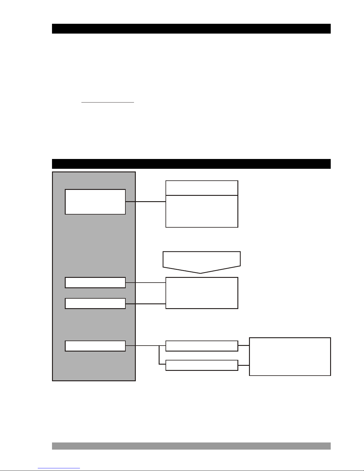
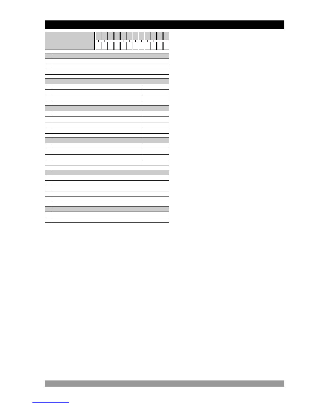
CONTENTS
3
Page 6
Page 9
Page 15
Page 22
Page 27
Page 29
Page 32

4
7.3 ADJUSTMENT OF SET1 AND SET2 VALUES
7.4 RESETTING COUNT VALUE AND OBSERVING TOTAL COUNT VALUE IN
COUNTER / “TOTALIZER COUNTER” FUNCTION
7.5 COUNTER / “TOTALIZER COUNTER” PARAMETERS
7.5.1 COUNTER / “TOTALIZER COUNTER” APPLICATIONS EXAMPLES
7.6 BATCH COUNTER PARAMETERS
7.6.1 BATCH COUNTER APPLICATIONS EXAMPLES
7.7 TIMER PARAMETERS
7.7.1 TIMER APPLICATIONS EXAMPLES
7.8 FREQUENCYMETER / TACHOMETER PARAMETERS
7.8.1 FREQUENCYMETER / TACHOMETER APPLICATIONS EXAMPLES
7.9 CHRONOMETER PARAMETERS
7.9.1 CHRONOMETER APPLICATIONS EXAMPLES
7.10 ACCESSING TO THE PROGRAM PARAMETERS
8.PROGRAM PARAMETERS.....................................................................................
9.FAILURE MESSAGES IN EZM-4450 PROGRAMMABLE TIMER & COUNTER ..
10.SPECIFICATIONS.................................................................................................
11.OTHER INFORMATION.........................................................................................
Page 102
Page 67
Page 100
Page 103

5
Manufacturer’s Name : EMKO ELEKTRONIK A.S.
Manufacturer’s Address : DOSAB, Karanfil Sk., No:6,
16369 Bursa, TURKEY
The manufacturer hereby declares that the product:
Product Name : Programmable Timer & Counter
Type Number : EZM-4450
Product Category : Electrical equipment for measurement, control and
laboratory use
Conforms to the following directives :
2006 / 95 / EC The Low Voltage Directive
2004 / 108 / EC The Electromagnetic Compatibility Directive
has been designed and manufactured to the following specifications:
EN 61000-6-4:2007 EMC Generic Emission Standard for Industrial Environments
EN 61000-6-2:2005 EMC Generic Immunity Standard for Industrial Environments
EN 61010-1:2001 Safety Requirements for electrical equipment for measurement, control
and laboratory use
When and Where Issued Authorized Signature
nd
16 October 2009 Name : Serpil YAKIN
Bursa-TURKEY Position : Quality Manager
EU DECLARATION OF CONFORMITY

6
EZM Series Programmable Timer & Counter can be used in package machines,
production and quality control rollers, in cutting and processing machine of glass, plastic, marble,
sheet, iron, fabric all measuring and controlling of dimension, count, total c unt, speed, cycle,
productivity, time and can be adapted easily to all mechanical construction and automation
system. They can be used in many application with their control outputs, serial communication
unit and output modules.
o
Some application fields which they are used are below:
1.Preface
Output Module-1
Supply Voltage
Input
Optional
1.1 General Specifications
EZM-4450
Optional
Standard
Standard
Universal Supply Input
100-240 VV, 50/60Hz
Output Module-2
Serial Communication RS-232
RS-485
Low Voltage (optional)
Supply Input
24VV50/60Hz, 24VZ
Application Fields
Glass
Plastic
Marble
Sheet iron
Automative
Machine production industries
Control Output
Alarm Output
Optional
Relay, SSR Driver, Digital
(Transistor) Output
Module
Baud Rate from 1200
to 19200
Modbus ASCII or RTU
Protocol

7
EzM-4450 ( 48x48 1/16 DIN)
Supply Voltage
100-240VV(- ) 50/60Hz15%;+10%
24 VV(- 50/60Hz 24VZ(-15%;+10%) 15%;+10%)
A
A
1
00
0
01
1
02
2
03
3
0
1
2
None -
Counter / “Totalizer Counter”
Relay Output Module(3A@250VVResistive Load ) EMO-400
Batch Counter
SSR Driver Output Module EMO-410
Frequencymeter and Tachometer
Digital(Transistor) Output Module EMO-420
Timer
None
RS-232
RS-485
2
BC D E FG HI /
/
U V W Z/
/
Serial CommunicationD
-
EMC-400
EMC-410
Product Code
1.2 Ordering Information
0
Customer (Maximum 240VV(- ))50/60Hz15%;+10%9
c
00 0 0
4 Chronometer
0
1
NPN
PNP
Product Code
Module-1FG
00
01
02
03
None -
Relay Output Module(3A@250VVResistive Load ) EMO-400
SSR Driver Output Module EMO-410
Digital(Transistor) Output Module EMO-420
Product Code
Module-2HI
Function of DeviceU
Input TypeV
VSymbol means Vac,
ZSymbol means Vdc
WSymbol means Vac and Vdc
All order information of EZM-4450
Programmable Timer&Counter are given on
the table at left. User may form appropriate
device configuration from information and
codes that at the table and convert it to the
ordering codes.
Firstly, supply voltage then output
modules and other specifications must be
determined. Please fill the order code blanks
according to your needs.
Please contact us, if your needs are
out of the standards.

8
1.3 Warranty
EMKO Elektronik warrants that the equipment delivered is free from defects in material and
workmanship. This warranty is provided for a period of two years. The warranty period starts from
the delivery date. This warranty is in force if duty and responsibilities which are determined in
warranty document and instruction manual performs by the customer completely.
1.4 Maintenance
Repairs should only be performed by trained and specialized personnel. Cut power to the device
before accessing internal parts.
Do not clean the case with hydrocarbon-based solvents (Petrol, Trichlorethylene etc.). Use of
these solvents can reduce the mechanical reliability of the device. Use a cloth dampened in ethyl
alcohol or water to clean the external plastic case.

9
In package ,
- One piece unit
- Two piece mounting clamp
- One piece instruction manual
A visual inspection of this product for possible damage occured during shipment is
recommended before installation. It is your responsibility to ensure that qualified
mechanical and electrical technicians install this product.
If there is danger of serious accident resulting from a failure or defect in this unit, power
off the system and separate the electrical connection of the device from the system.
The unit is normally supplied without a power switch or a fuse. Use power switch and fuse
as required.
Be sure to use the rated power supply voltage to protect the unit against damage and to
prevent failure.
Keep the power off until all of the wiring is completed so that electric shock and trouble
with the unit can be prevented.
Never attempt to disassemble, modify or repair this unit. Tampering with the unit may
results in malfunction, electric shock or fire.
Do not use the unit in combustible or explosive gaseous atmospheres.
During the equipment is putted in hole on the metal panel while mechanical installation
some metal burrs can cause injury on hands, you must be careful.
Montage of the product on a system must be done with it’s fixing clamps. Do not do the
montage of the device with inappropriate fixing clamp. Be sure that device will not fall
while doing the montage.
It is your responsibility if this equipment is used in a manner not specified in this
instruction manual.
Before beginning installation of this product, please read the instruction
manual and warnings below carefully.
2.Installation
c

2.1 General Description
2.2 Dimensions
10
Panel surface
(maximum thickness 5mm / 0.2 inch)
48 mm / 1.89 inch
48 mm /1.89 inch
Maximum 5mm / 0.2 inch
104.5 mm/ 4.11 inch11.5 ± 1 mm /0.45 inch
Terminal protection cover
Product Label
Front Panel
IP65 protection
Mounting Clamp
O1
O2
S1
S2
EZM-4450
TOTAL
PRESET
SET1 SET2
Timer & Counter

2.3 Panel Cut-Out
11
65 mm / 2.56 inch (min)
46 mm / 1.81 inch (min)

c
12
Operating Temperature : 0 to 50 °C
Max. Operating Humidity : 90% Rh (non-condensing)
Altitude : Up to 2000m.
Operating Conditions
Forbidden Conditions:
Corrosive atmosphere
Explosive atmosphere
Home applications (The unit is only for industrial applications)
During installation into a metal panel, care should be taken to avoid injury from
metal burrs which might be present. The equipment can loosen from vibration
and become dislodged if installation parts are not properly tightened. These
precautions for the safety of the person who does the panel mounting.
2.4 Environmental Ratings
2.5 Panel Mounting
c
1-Before mounting the device in
your panel, make sure that the
cut-out is of the right size.
2-Check front panel gasket
position
3-Insert the device through the
cut-out. If the mounting clamp
are on the unit, put out them
before inserting the unit to the
panel.
1
2
3

13
1-Loosen the screws.
2-Lift the locking tabs located on both
the right and left hand sides and pull the
fixing clamp from the device while
holding the unit in place.
3-Pull the unit through the front side of
the panel
Before starting to remove the unit from panel, power off the unit and the related
system.
Montage of the unit to a system must be done with it’s own fixing clamps. Do not
do the montage of the device with inappropriate fixing clamps. Be sure that
device will not fall while doing the montage.
The unit is designed for panel mounting.
1-Insert the unit in the panel cut-out from
the front side.
2-Insert the mounting clamp from the
rear side of the unit and screw up the
fixing screws until the unit completely
immobile within the panel
2.6 Installation Fixing Clamp
2.7 Removing from the Panel
c
c
1
2
3
1
2

14
1
1
1
1
1 4
4
ON
ON
ON
ON
ON ON
ON
OFF
Counter
&
Totalizer
Batch
Counter
Timer
Tacho
Chrono
PNP
NPN
OFF
OFF
OFF
OFF OFF
OFF
2
2
2
2
2
3
3
3
3
3
7
12 VZ
Max. 50mA
0 VZ
ChA
ChB
PAUSE
RESET
100 to 240 VV
1
8
2
9
MODULE-1
MODULE-2
3
10
4
11
5
12
6
N L
50/60 Hz - 6VA
DIP Switch is under cover and cover is on top side of the device
NPN PNP
Function Selection
2.8 Selection of Operation Function and Input Type with DIP Switch
Operation function and input type ( NPN / PNP ) can be changed by DIP switch
on the device.
c
1
2
3
ONOFF
1
2
3
ONOFF
1
2
3
ONOFF
1
2
3
ONOFF
1
2
3
ONOFF
4
ONOFF
4
ONOFF
Batch Counter
Timer
Frequencymeter and
Tachometer
Chronometer
Input Type Selection
1ONOFF
2
3
4
Counter /
“Totalizer Counter”

3.1 Terminal Layout and Connection Instructions
15
1
7
2
8
3
9
4
10
5
11
6
12
6 mm / 0.236 inch
Wire Size:
18 AWG / 1 mm²
Solid /Stranded
12 screws terminal
M3
0.5 Nm
a
Optional connections
Torque 0.5 Nm
Screw driver 0.8x3mm
You must ensure that the device is correctly configured for your application.
Incorrect configuration could result in damage to the process being controlled,
and/or personal injury. It is your responsibility, as the installer, to ensure that
the configuration is correct.
Parameters of the device has factory default values. These parameters must be
set according to the system’s needs.
Only qualified personnel and technicians should work on this equipment. This
equipment contains internal circuits with voltage dangerous to human life.
There is severe danger for human life in the case of unauthorized intervention.
Be sure to use the rated power supply voltage to protect the unit against
damage and to prevent failure.
Keep the power off until all of the wiring is completed so that electric shock and
trouble with the unit can be prevented.
3.Electrical Wirings
c
c
c
c

16
1
7
2
8
3
9
4
10
5
11
6
12
MODULE-1 MODULE-2
a
Communication
Scocket
Max 50mA
Ch A
Ch B
PAUSE
RESET
12 V Z
0 V Z
Counting Inputs
Optional Output Module Terminals
Relay Output Module
SSR Driver Module
Digital (Transistor) Output Module
c
Sensor
Supply Voltage
3.2 Electrical Wiring Diagram
Electrical wiring of the device must be the same as ‘Electrical Wiring Diagram’
below to prevent damage to the process being controlled and personnel injury.
Supply Voltage Input
100-240VV(- ) 50/60Hz - 6VA
24 VV(- 50/60Hz - 6VA
24VZ(-
(It must be determined in order)
15%;+10%
15%;+10%)
15%;+10%) - 6W
P/N : EZM-4450
Y
c

3.3 Connection of Device Supply Voltage Input
17
11
NL
12
Y
11
L
12
Y
c c
aa
N
Connection of Universal
Supply Voltage Input
Connection of Low Voltage
24 VWSupply Voltage Input
Supply Voltage
100 - 240 VV(-15%;+10%)
50/60Hz
Supply Voltage
24VV(-15%;+10%) 50/60Hz
or 24VZ(-15%;+10%)
Note-1
Power
Supply
Switch
External
Fuse
(1 AVT)
Note-1 :
There is internal 33R W fusible flameproof resistor in 100-240 VV50/60Hz
There is internal 4R7 W fusible flameproof resistor in 24VV50/60Hz and 24VZ
Note-2 : “L” is “+”, “N” is “-” for 24VZsupply voltage
Note-3 : External fuse is recommended.
External
Fuse
(24VV: 1 AVT)
(24VZ: 1 AZT)
Note-2
Note-1
Power
Supply
Switch
Supply voltage range must be determined in order. While installing the unit,
supply voltage range must be controlled and appropriate supply voltage must
be applied to the unit. Controlling prevents damages in unit and system and
possible accidents as a result of incorrect supply voltage.
There is no power supply switch on the device. So a power supply switch must
be added to the supply voltage input. In accordance with the safety regulations,
the power supply switch shall bring the identification of the relevant
instrument.Power supply switch shall be easily accessible by the user.
Power switch must be two poled for seperating phase and neutral. On/Off
condition of power switch is very important in electrical connection. On/Off
condition of power switch must be signed for preventing the wrong connection.
If an external fuse is used, it must be on phase connection in Vsupply input.
If an external fuse is used, it must be on (+) line connection in Zsupply input.
Make sure that the power supply voltage is the same indicated on the
instrument.
Switch on the power supply only after that all the electrical connections have
been completed.
The instrument is protected with an internal fuse (Please refer to Note1 for
information). In case of failure it is suggested to return the instrument to the
manufacturer for repair.
c
c
c
Fuse
Fuse
Note-3
Note-3

18
1 42 53 6
0 V Z
ChA
ChB
PAUSE
PROX. PROX.
RESET
NPN NPN
1 42 53 6
12 V Z
Max. 50mA
0 V Z
ChA
ChB
PAUSE
Switch
PROX. PROX.
Switch
RESET
PNP PNP
12 V Z
Max. 50mA
NOTE-1
Switch
Switch
DIP SWITCH ADJUSTMENT : PNP
NOTE-1
3.4.1 Proximity & Switch Connection
3.4 Counting Input Connection
DIP SWITCH ADJUSTMENT : NPN
NOTE-1 : Auxiliary power supply for external transmitter
12VZ± 10%, 50 mA maximum with short circuit protection
NOTE-2 : Reset and Pause inputs have protection time against electrical contact
debounce. Protection time can be set with parameter. (2-250 msec.)
NOTE-2
NOTE-2

19
1 42 53 6
ChA
ChB
PAUSE
INCREMENTAL ENCODER
10 to 30V Z
RESET
1 42 53 6
ChA
ChB
PAUSE
INCREMENTAL ENCODER
10 to 30V Z
RESET
Switch
Switch
NOTE-1
Switch
Switch
NOTE-1
0 V Z
12 V Z
MaX. 50mA
0 V Z
12 V Z
Max. 50mA
3.4.2 Incremental Encoder & Switch Connection
DIP SWITCH ADJUSTMENT : PNP
DIP SWITCH ADJUSTMENT : NPN
NOTE-1 : Auxiliary power supply for external transmitter
12VZ ± 10%, 50 mA maximum short circuit protection
NOTE-2
NOTE-2
NOTE-2 : Reset and Pause inputs have protection time against electrical contact
debounce. Protection time can be set with parameter. (2-250 msec.)

20
3.4.3 Switch Connection
1 42 53 6
ChA
ChB
PAUSE
RESET
Switch
Switch
1 42 53 6
ChA
ChB
PAUSE
RESET
Switch
Switch
NOTE-1
Switch
Switch
Switch
Switch
NOTE-1
NOTE-1 : Auxiliary power supply for external transmitter
12VZ± 10%, 50 mA maximum short circuit protection
0 V Z
12 V Z
Max. 50mA
0 V Z
12 V Z
Max. 50mA
DIP SWITCH ADJUSTMENT : PNP
DIP SWITCH ADJUSTMENT : NPN
NOTE-2
NOTE-2
NOTE-2 : Reset and Pause inputs have protection time against electrical contact
debounce. Protection time can be set with parameter. (2-250 msec.)
Other manuals for EZM-4450
1
Table of contents
Other EMKO Timer manuals