Page 1 of 2 11775 E. 45th Ave. Denver, CO 80239 Ph: 1-800-880-1180 Fax: 303-695-7633©2023 American Lighting, Inc. REV2324 www.AmericanLighting.com
SPEKTRUM+ SMART RECEPTACLE120V
INSTALLATION INSTRUCTIONS
SPKPL-OUTLETW-2S-WH
SAFETY INFORMATION
• Read all installation instructions before beginning; if not qualified, do not attempt
installation. Contact a qualified electrician.
• To reduce the risk of fire, electric shock, or injury to persons, pay close attention
to this manual and stay within its guidelines when using this product. Save these
instructions for future use.
• This product is suitable for indoor use in dry locations only.
• Do not submerge in liquids nor use the product in the vicinity of standing water or
other liquids, or where water can accumulate.
• Do not use if there is any damage to the product; inspect periodically.
• Do not install in tanks or enclosures of any kinds.
• This product utilizes Bluetooth® 2.4Ghz wireless technology.
• The rated input power for this unit is 100-120V AC 60Hz.
• The maximum rated current for this unit is 10A.
• The standby power consumption of this unit is ≤0.5W.
• This unit is not intended to be used in conjuction with a any dimmer.
These products may represent a possible shock or fire
hazard if improperly installed or attached in any way.
Products should be installed in accordance with these
instructions, current electrical codes, and/or the current
National Electric Code (NEC).
Do not exceed maximum recommended loads! 10A total.
Electricity can cause personal injury and property
damage if handled improperly.If you are not sureabout
any part of these instructions,please seek professional
assistance from a qualified electrician. Ensure all work
meets applicable local and national codes.
WARNING
WARNING
WARNING: RISK OF ELECTRIC SHOCK
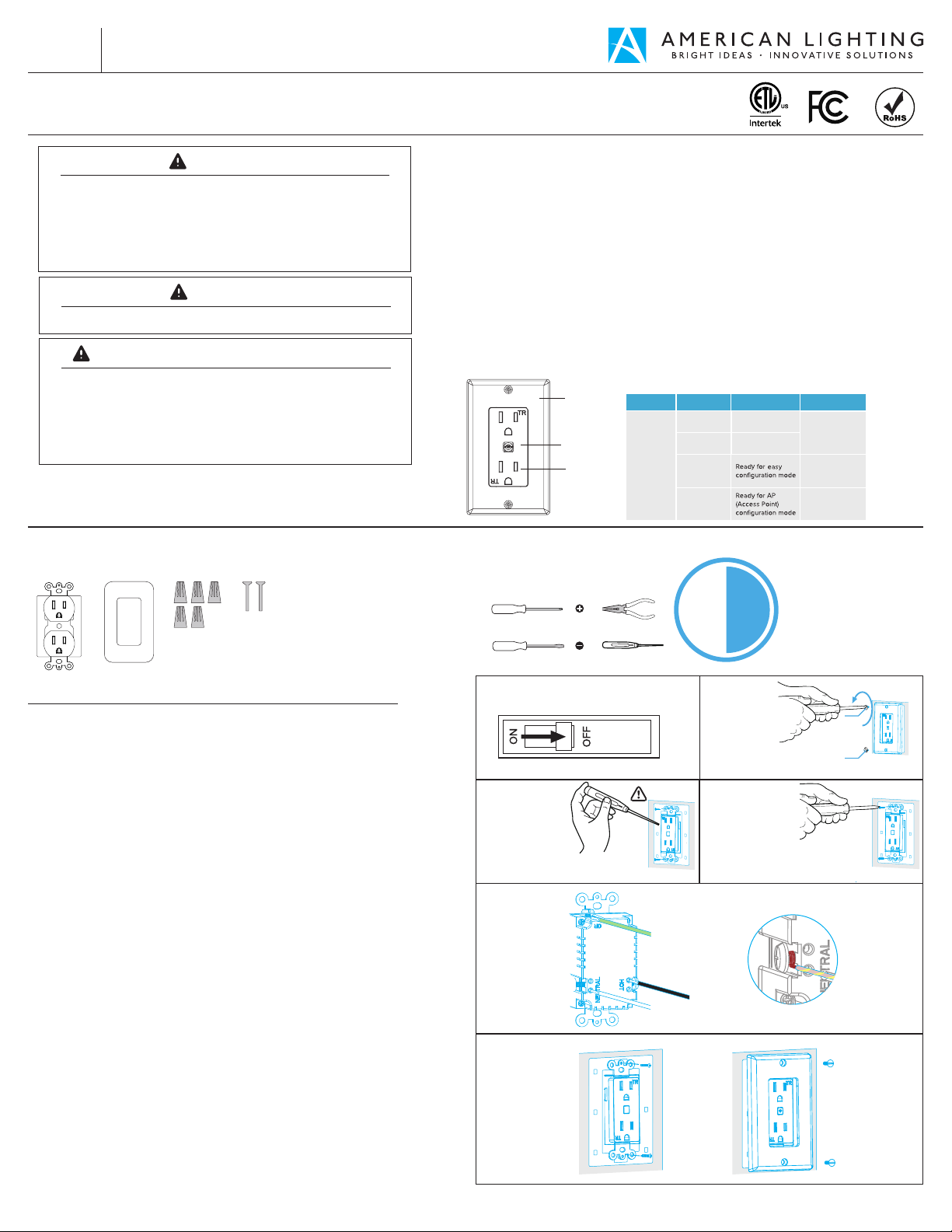
FIGURE 1 FIGURE 2
FIGURE 3
FIGURE 5
FIGURE 4
Tools Needed:
Approximately
30 minutes to install
and setup receptacle
Receptacle Cover Panel Wire Nuts Screws
Phillips Head Screwdriver
Bluetooth Pairing
Button
Power Socket
Pliers
Flat-Head Screwdriver Voltage Tester
CONTENTS: CONSIDERATIONS:
INSTALLATION:
Disconnect power from source prior to attempting installation.
Make all connections and mount in place prior to providing power to system. This
product is designed to be installed in a single gang junction box.
1. Locate the circuit breaker panel and turn o the power to each switch being
replaced/installed. More than one circuit breaker may need to be turned o.
See Figure 1.
2. Remove the existing faceplate by unscrewing the mounting screws and pull it
away from the wall. See Figure 2.
3. Verify power is o. Once the faceplate is removed from the existing receptacle,
use an electrical voltage tester to test all wires connected to the switch to ensure
there is no voltage in the circuit. See Figure 3.
4. Unscrew the mounting screws from the junction box and pull out the existing
receptacle. See Figure 4.
5. Connect Smart Receptacle to wires from home wiring. Note which wire goes to
which terminal (Green/Ground, White/Neutral, Black/Hot) See Figure 5.
- Note: The color of your wire may be dierent from the color shown in Figures.
6. Use two long screws to connect Smart Receptacle to junction box.
See Figure 6.
7. Use two short screws to connect faceplate to Smart Receptacle. See figure 6.
8. To set up device once installed, press the bluetooth connectivity button in the
middle of the receptacle for 8 seconds. A blinking light will indicate the device is
in pairing mode.
9. Open the Spektrum+ Smart App and click the “+” button to add a device.
10. Add the Smart Plug device from the auto-add menu. If the device does not
show up automatically, use the “add manually” option to add the device manually.
11. Follow the pairing instructions on screen.
12. Once device is paired, utilize the Spektrum+ App to configure settings for
device.
30min
Switch Status RemarksLight StatusLight Color
OFF
ON
Power OFF(Default)
Power ON(Default)
Blink Quickly
(0.5s )
Blink Slowly
(1s )
Cover Panel
FIGURE 6
1
2
GREEN / GROUND
BLACK / HOT
WHITE / NEUTRAL
Blue