American Magnetics 150 User manual

1 August 18, 2003
INSTALLATION, OPERATION AND MAINTENANCE
INSTRUCTIONS FOR THE AMI
MODEL 150A
LIQUID HELIUM LEVEL METER
I. INTRODUCTION
The American Magnetics, Inc. (AMI) Model 150A is a compact, fully portable Liquid Helium
Level Meter providing simple and easy operation. The instrument is battery operated and when
used in conjunction with an AMI LHe Level Sensor, provides a truly portable means of
measuring liquid helium levels at any location. The sensor connects to the instrument via a
standard DB9 connector. The instrument displays 0-100% of sensor maximum active length
immersed in LHe. The instrument can be used with AMI sensors with active lengths of up to 60
inches. The instrument is powered by sealed lead-acid batteries. A standard AC-DC adapter
(either 120VAC or 230VAC) is supplied with the unit for charging the batteries. Since battery
energy consumption is strongly dependent on the LHe level being measured, AMI has developed
a special "battery saver" circuit which reduces the power drain from the batteries as more of the
sensor becomes superconducting. Power requirements decrease as LHe level increases. A front
panel POWER LED is provided to indicate sufficient battery power exists to make an accurate
level reading.
The CE mark applies to the handheld unit and the European AC adapter. The North American
AC adapter is not CE marked.
II. SPECIFICATIONS (at 25 °C unless stated otherwise)
Input Power (instrument) Sealed lead-acid battery (6VDC)
Input Power (AC adapter) 90VAC to 132VAC 50/60 Hz, or 180VAC to 264VAC
50/60 Hz (depending on specified AC adapter model)
Operating temperature (instrument) 0 to 50 °C non-condensing
Operating temperature (AC adapter) 0 to 40 °C non-condensing
Sensor active length range 1 inch to 60 inches
Linearity 0.5% of full scale
Absolute Calibration 0.5% of full scale
2% of full scale (from 0 to 50 ºC)
Probe Current 75 mA nominal
Battery Life Typically 1,000 readings with a 60" sensor.
* Under extreme radiated electromagnetic field conditions (3V/m @ 80MHz to 1GHz) the
accuracy may be degraded by an additional +/- 1.2%

2 August 18, 2003
III. INSTALLATION
The sensor connector is potentially supplied with hazardous line voltage (~70VDC).
A. Carefully remove the instrument from the shipping carton and remove all the packing
material. Inspect the equipment for any physical damage that may have occurred during
shipment.
NOTE: If there is any shipping damage save all packing
material and contact the shipping representative to file a
damage claim. Do not return the instrument to AMI unless prior
authorization has been received. (See Section IX)
B. Install the liquid helium sensor as per the AMI document "Installation, Operation And
Maintenance Instructions for the AMI Liquid Helium Level Sensor."
C. To facilitate mobility, the Model 150A is equipped with a single standard DB9 connector
which connects the instrument to a sensor. Connect the LHe sensor wires to the DB9
connector terminals as follows:
Wire Color DB9 Pin Number Signal Name
Red 1 I+
Yellow 6 V-
Black 7 I-
Blue 8 V+
IV. OPERATION
A. Connect the instrument to the sensor via the sensor (DB9) connector. Refer to Figure 1.
B. Depress the READ push-button switch on the front panel to read the LHe level. The
button should be held for sufficient time to allow the meter reading to stabilize.
NOTE: The front panel LED should light to indicate sufficient
sensor current exists to make an accurate reading. The
instrument is calibrated to read the helium level directly on the
panel meter. If the LED does not light during the level
measurement, recharge the batteries. When the READ button is
released, the unit is automatically deenergized.
!

3 August 18, 2003
Fig. 1. Model 150A

4 August 18, 2003
V. MAINTENANCE
A. The instrument was shipped with a full charge on the batteries. Operating under a
maximum power consumption of measuring a 60" sensor in a near empty dewar, the unit
is capable of making approximately 1,000 level measurements before battery recharging
is required.
B. The failure of the front panel LED to light when a measurement is being made indicates
low battery power. If the front panel LED fails to stay lit during a measurement, the
batteries should be recharged. The supplied AC adapter plugs into a 90VAC to 132VAC
50/60Hz (or optional 180VAC to 264VAC 50/60Hz for the European model) source and
into the jack provided on the side of the instrument. The batteries should be charged for
a minimum of 1 hour before taking more readings; subsequently, as soon as it is feasible,
batteries should be charged for at least 72 hours to fully charge the battery.
NOTE: Best battery performance will be realized by charging
the Model 150A continuously whenever it is not being used.
NOTE: The AC adapter is rated for connection to Category II
mains voltages.
NOTE: Only AMI approved AC adapters should be used on the
device.
NOTE: Only an authorized service representative should replace
the factory installed batteries.
C. As part of the routine maintenance, keep the exterior surfaces of the instrument clean by
gently wiping with a damp cloth moistened with a mild detergent.
VI. CALIBRATION
The instrument is calibrated for a specific sensor length before shipping and should never
need adjustment. However, the calibration procedure is included for your information.
All AMI sensors have a resistance of 4.56 ohms/cm (active length) when in the normal
state and maintained just above the transition temperature of 10K. Thus, if you are using
a 50 cm sensor, you will need a 50 x 4.56 = 228.0 ohm resistor for calibration purposes
(ensure that the resistor power rating is sufficient and that its temperature coefficient is
adequately low such that self-heating due to the 75 mA excitation current does not cause
excessive shift in the resistor’s resistance).
NOTE: The active length of a sensor is usually 1" less than its
overall length.
NOTE: Disconnect the helium level sensor from the instrument.

5 August 18, 2003
A. CHANGING SENSOR ACTIVE LENGTH RANGE
NOTE: IF THIS STEP IS REQUIRED, IT SHOULD BE
PERFORMED BY QUALIFIED SERVICE PERSONNEL. SEE
THE QUALIFIED SERVICE PERSONNEL SECTION. There
are two sensor active length ranges — 1”-7.99” and 8”-60”. If
the instrument is currently calibrated for a sensor in a particular
range and the new sensor is in the same range, then this step
does not need to be taken—the range-setting jumpers are
already in the correct position. For example, if the instrument is
currently calibrated to an 18” sensor active length, and is being
re-calibrated to a 12” sensor active length, then the jumpers are
already both in the 8”-60” position; there is no need to open up
the unit. All needed adjustments can be made through the side
access holes in the lid.
B. ACTIVE LENGTH CALIBRATION
1. Jumper the I+ and V+ contacts (pins 1 and 8) on the SENSOR connector together
and connect to one side of the calibration resistor. Jumper the I- and V- contacts
(pins 6 and 7) on the sensor connector together and connect to the other side of
the calibration resistor. The value of the calibration resistor should be (4.56
ohms) x (the active length of the sensor in cm); remember that the active length
of AMI standard sensors is 1 inch less than the overall length.
2. Temporarily install a short circuit (using a clip lead or other means) across the
calibration resistor.
3. Depress the READ switch.
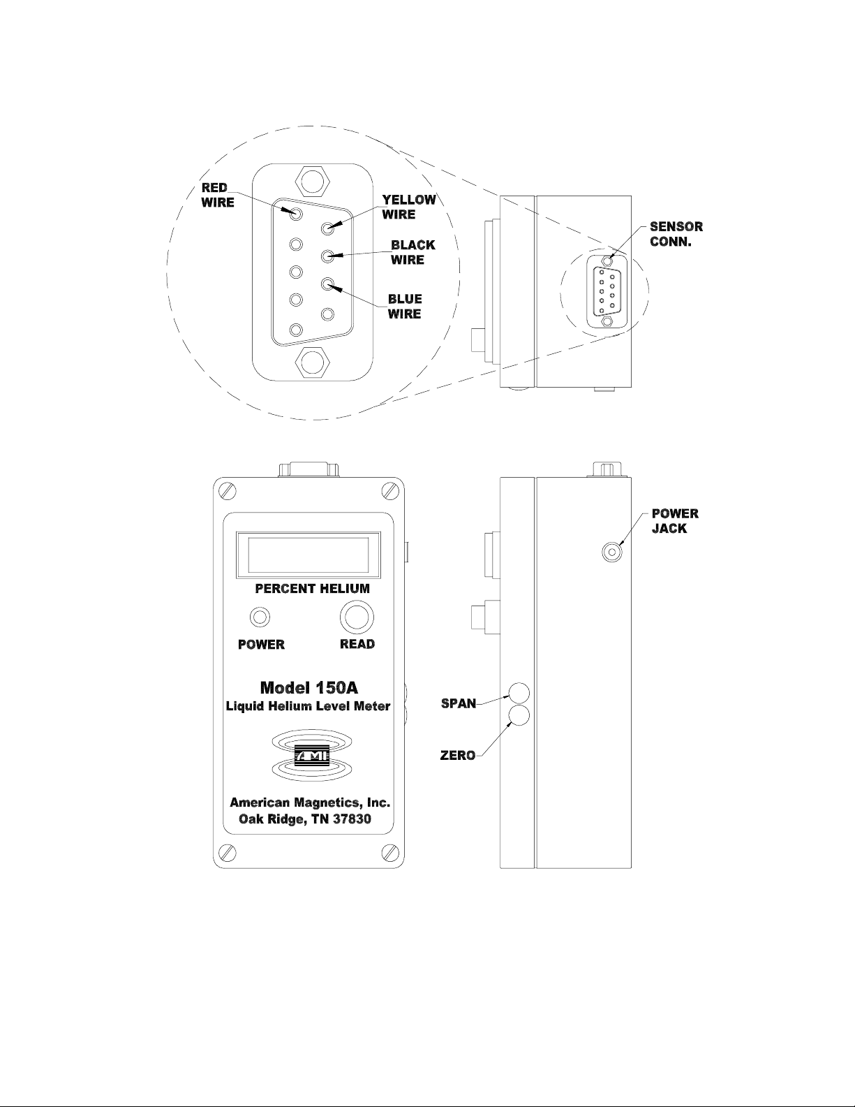
4. Adjust the SPAN potentiometer located on the circuit board through the side
access hole in the lid until the display LCD reads 100.0. Refer to Figure 1.
5. Release the READ switch.
6. Remove the short from the calibration resistor.
7. Depress the READ switch.
8. Adjust the ZERO potentiometer located on the circuit board through the side
access hole in the lid until the display LCD reads 0.0. Refer to Figure 1.
9. Release the READ switch.
10. Repeat steps 2 through 9 until neither potentiometer needs adjusting.
11. Remove the jumper wires and calibration resistor.
12. The calibration procedure is complete.
13. Reconnect the sensor to the instrument.

6 August 18, 2003
III. TROUBLESHOOTING
A. No LED power indication when the READ switch is depressed
1. Verify the sensor is properly connected to the SENSOR connector. The POWER
LED indicates proper sensor current; consequently, the POWER LED will not
light if the sensor is not connected properly even though batteries are fully
charged.
2. Recharge the batteries.
3. Qualified Service Personnel ONLY: Check the condition of the internal batteries.
Verify no corrosion exists.
B. Meter reads 100.0 when the READ switch is depressed.
1. Verify that a sensor is properly connected to the instrument.
2. Ensure the helium level is not actually at the top of the sensor.
C. Other erroneous level indications.
Most inoperative instruments are traced to improper wiring between the sensor and the
instrument. Verify the sensor is connected in accordance with the color code outlined in
the installation section (see table in installation section and Figure 1).
If the cause of the problem cannot be located, please call an AMI Technical Support
representative at (865) 482-1056. Our standard business hours are Monday through
Friday, 8:00 a.m. to 4:30 p.m. Eastern Time.
IV. QUALIFIED SERVICE PERSONNEL (QSP)
A. ESD
This instrument contains components which are susceptible to damage by Electrostatic
Discharge (ESD). Take the following precautions whenever the cover of the instrument
is removed.
1. Disassemble the instrument only in a static-free work area.
2. Use a conductive workstation or work area to dissipate static charge.
3. Use a high resistance grounding wrist strap to reduce static charge accumulation.
4. Ensure all plastic, paper, vinyl, Styrofoamtm, and other static generating materials
are kept away from the work area.
5. Minimize the handling of the instrument and all static sensitive components.
6. Keep replacement parts in static-free packaging.

7 August 18, 2003
7. Do not slide static sensitive devices over any surface.
8. Use only antistatic type desoldering tool.
9. Use only grounded-tip soldering irons.
B. CHANGING SENSOR ACTIVE LENGTH RANGE
1. Before removing cover, make sure that unit has been deenergized for at least 30
seconds.
2. ONLY IF NEEDED, remove the electronics from the enclosure to allow access
to the printed circuit board, by following the steps in this section.
NOTE: The electronics inside the instrument are
STATIC ELECTRICITY sensitive. Extreme care should
be used when handling by following static sensitive
handling procedures.
3. Open the Model 150A enclosure by loosening the four captive lid screws.
4. Record the position of the three internal cable connectors (including their
orientation) attached to the printed circuit board; then disconnect them from the
printed circuit board.
5. Remove the READ switch cap and guard (cap is pulled off and guard is
unscrewed).
6. Apply slight pressure to the POWER LED and READ switch from the front of
the Model 150A and gently remove the printed circuit board from the back.
NOTE: Gently removing the printed circuit board will
ensure that the POWER LED disengages from its
mounting socket in the front panel and the LCD display
disengages from its socket on the board with no damage
to either.
7. When recalibrating for a different sensor-length range, two jumpers (at J6 and J7)
on the circuit board must be changed. Set both jumpers to either 1”-7.99” or 8”-
60” as appropriate for the active length of the sensor to which the instrument will
be calibrated.
NOTE: The ends of J6 and J7 nearest the asterisks
(“*”) are where the jumpers should be set for the 8”-
60” range. Set the jumpers to the ends of J6 and J7
farthest from the asterisks for the 1”-7.99” range.

8 August 18, 2003
8. Carefully reinstall the printed circuit board into the front panel lid, aligning the
LCD display pins with the connector in the printed circuit board, aligning the
POWER LED with its socket in the lid, and aligning the READ switch with its
opening in the lid.
9. Reinstall the READ switch cap and guard.
10. Reconnect all the internal cable connectors to the printed circuit board with the
same orientation and position as recorded in Step 3.
11. Close up the Model 150A enclosure by retightening the four hold-down screws
in the front panel lid, attaching the lid to the base.
V. WARRANTY
All products manufactured by AMI are warranted to be free of defects in materials and
workmanship and to perform as specified for a period of one year from date of shipment. In the
event of failure occurring during normal use, AMI, at its option, will repair or replace all products
or components that fail under warranty, and such repair or replacement shall constitute a
fulfillment of all AMI liabilities with respect to its products. Since, however, AMI does not have
control over the installation conditions or the use to which its products are put, no warranty can
be made of fitness for a particular purpose, and AMI cannot be liable for special or consequential
damages. All warranty repairs are F.O.B. Oak Ridge, Tennessee, USA.
VI. RETURN AUTHORIZATION
Items to be returned to AMI for repair (warranty or otherwise) require a return authorization
number to ensure your order will receive proper attention. Please call an AMI representative at
(865) 482-1056 for a return authorization before shipping any item back to us.

Declaration of Conformity
Application of Council Directives: Low Voltage Directive 72/23/EEC
EMC Directive 89/336/EEC
Manufacturer's Name: American Magnetics, Inc.
Manufacturer's Address: 112 Flint Road,
P.O. Box 2509
Oak Ridge, TN 37831-2509
U.S.A.
Type of Equipment: Liquid Level Instruments
Model Numbers: Model 150
Standards to which Conformity is Declared:
Safety: EN 61010-1 (2001)
EMC: EN55 022 (2003) Class A
EN61326 (2002) / EN61000-4-2 (2002) 8kV AD, 4kV CD
EN61326 (2002) / EN61000-4-3 (2002) 3V/m, 80 - 1000MHz
EN61326 (2002) / EN61000-4-8 (2001) 30A/m, 50Hz
I, the undersigned, hereby declare that the equipment specified above complies with the require-
ments of the aforementioned Directives and Standards and carries the "CE" mark accordingly.
Claude H. Bernard September 10, 2003
Quality Manager
American Magnetics, Inc.
Oak Ridge, TN, U.S.A.
Table of contents