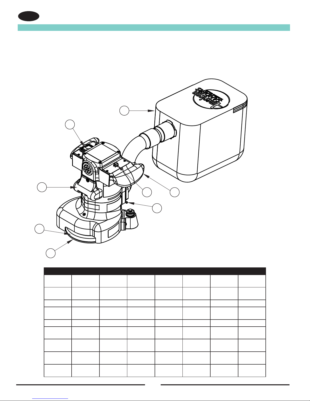
10
Machine Setup
EN
This sanding machine is designed to be operated with a remote vacuum
dust collection system or with the included dust bag.
Preparing Remote Vacuum Dust Collection Systems
To prepare the machine for remote vacuum dust collection systems that
have a 2” hose end, follow this procedure:
1. Install 2” hose end (gure 1, A) directly over the exhaust tube
(gure 1, B).
2. The exhaust tube can be rotated for optimum convenience.
To prepare the machine for remote vacuum dust collection systems that
have a 1 ½” hose end, follow this procedure:
1.
Install the 2” x 1½” hose end adaptor (Part No. 30563A) (gure 1, C)
over the exhaust tube (gure 1, B).
2. Insert 1 ½” hose end (gure 1, D) into the adaptor (gure 1, C).
NOTE: Start the remote vacuum collection system before operation.
Preparing to use the included dust bag
To prepare the machine for use with the included dust bag (Part No.
53544B), follow this procedure:
1. Install the dust bag by pressing the end onto the exhaust tube
until the ring locks into the groove (gure 2). This is best done
by pressing on the back of the bag opening with the palm of your
hand.
2. The exhaust tube can be rotated for optimum convenience.
3. To remove the dust bag from the exhaust tube, pry up the end
of the bag opening to partially release the internal rib from the
groove, then pull.
4. To empty the dust bag, unzip the disposal ap and force contents
out by inverting the bag.
NOTE: For best results, empty frequently. Follow all warnings
posted in this manual and on the dust bag.
Preparing the Machine for Operation
1. Familiarize yourself with the machine. Read all danger, warning,
and caution statements and the Owner’s Manual before operating
this machine. If you or your operator cannot read English,
have this manual explained fully before attempting to operate this
machine.
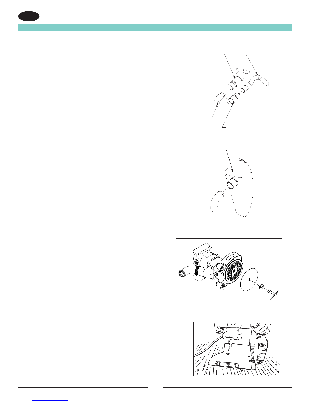
2. Remove screw and abrasive retainer. Center abrasive on pad
and secure with abrasive retainer and screw. (Figure 3)
3.
Return machine to upright position and tilt machine back on casters
until
it comes to rest on the exhaust bracket. Machine will be in a
reclined position.
Do not allow machine to rest on pad especially
after use, or compression set may take place within elastomer on
pad. This will create a at spot and bounce during use. (Figure 4)
EN ENGLISH
-8- American Sanders Operator’s Manual (EN) - Super 7R
Install the dust bag by
pressing the end onto the
exhaust tube until the ring
locks into the groove.
A
2” Hose from
vacuum system
(not included)
1.5” Hose from
vacuum system
(not included)
D
B
C
Exhaust Tube
(30563A) 2” Tube x 1.5” hose adaptor
Figure 1
Figure 2
MACHINE SET-UP
This sanding machine is designed to be operated with a remote vacuum
dust collection system or with the included dust bag.
Preparing Remote Vacuum Dust Collection Systems
To prepare the machine for remote vacuum dust collection systems that
have a 2” hose end, follow this procedure:
1. Install 2” hose end (gure 1, A) directly over the exhaust tube (gure 1,
B).
2. The exhaust tube can be rotated for optimum convenience.
To prepare the machine for remote vacuum dust collection systems that
have a 1 ½” hose end, follow this procedure:
1. Install the 2” x 1½” hose end adaptor (Part No. 30563A) (gure 1, C)
over the exhaust tube (gure 1, B).
2. Insert 1 ½” hose end (gure 1, D) into the adaptor (gure 1, C).
NOTE: Start the remote vacuum collection system before operation.
Preparing to use the included dust bag
To prepare the machine for use with the included dust bag (Part No.
53544B), follow this procedure:
1. Install the dust bag by pressing the end onto the exhaust tube until the
ring locks into the groove (gure 2). This is best done by pressing on
the back of the bag opening with the palm of your hand.
2. The exhaust tube can be rotated for optimum convenience.
3. To remove the dust bag from the exhaust tube, pry up the end of the
bag opening to partially release the internal rib from the groove, then
pull.
4. To empty the dust bag, unzip the disposal ap and force contents out
by inverting the bag.
NOTE: For best results, empty frequently. Follow all warnings posted
in this manual and on the dust bag.
Figure 1
EN ENGLISH
-8- American Sanders Operator’s Manual (EN) - Super 7R
Install the dust bag by
pressing the end onto the
exhaust tube until the ring
locks into the groove.
A
2” Hose from
vacuum system
(not included)
1.5” Hose from
vacuum system
(not included)
D
B
C
Exhaust Tube
(30563A) 2” Tube x 1.5” hose adaptor
Figure 1
Figure 2
MACHINE SET-UP
This sanding machine is designed to be operated with a remote vacuum
dust collection system or with the included dust bag.
Preparing Remote Vacuum Dust Collection Systems
To prepare the machine for remote vacuum dust collection systems that
have a 2” hose end, follow this procedure:
1. Install 2” hose end (gure 1, A) directly over the exhaust tube (gure 1,
B).
2. The exhaust tube can be rotated for optimum convenience.
To prepare the machine for remote vacuum dust collection systems that
have a 1 ½” hose end, follow this procedure:
1. Install the 2” x 1½” hose end adaptor (Part No. 30563A) (gure 1, C)
over the exhaust tube (gure 1, B).
2. Insert 1 ½” hose end (gure 1, D) into the adaptor (gure 1, C).
NOTE: Start the remote vacuum collection system before operation.
Preparing to use the included dust bag
To prepare the machine for use with the included dust bag (Part No.
53544B), follow this procedure:
1. Install the dust bag by pressing the end onto the exhaust tube until the
ring locks into the groove (gure 2). This is best done by pressing on
the back of the bag opening with the palm of your hand.
2. The exhaust tube can be rotated for optimum convenience.
3. To remove the dust bag from the exhaust tube, pry up the end of the
bag opening to partially release the internal rib from the groove, then
pull.
4. To empty the dust bag, unzip the disposal ap and force contents out
by inverting the bag.
NOTE: For best results, empty frequently. Follow all warnings posted
in this manual and on the dust bag.
Figure 2
EN
ENGLISH
American Sanders Operator’s Manual (EN) - Super 7R - 9 -
Figure 3
Figure 4
Figure 5
MACHINE SET-UP
Preparing the Machine for Operation
1. Familiarize yourself with the machine. Read all danger, warning, and caution
statements and the Owner’s Manual before operating this machine. If you or
your operator cannot read English, have this manual explained fully before
attempting to operate this machine.
2. Remove screw and abrasive retainer. Center abrasive on pad and secure with
abrasive retainer and screw. (Figure 3)
3. Return machine to upright position and tilt machine back on casters until it
comes to rest on the exhaust bracket. Machine will be in a reclined position.
Do not allow machine to rest on pad especially after use, or compression set
may take place within elastomer on pad. This will create a at spot and bounce
during use. (Figure 4)
OPERATING INSTRUCTIONS
1. Move machine to the location of your work. Set any exposed nails with ham-
mer and punch to avoid encounter with abrasive.
WARNING: Bodily injury could occur if power is applied to
the machine with the power switch already in the “ON” position. Always
check to assure that the power switch is in the “OFF” position before
applying power to the power cable.
2. Make sure the control switch is in the “Off” position then connect the supply
cable to an appropriately grounded fused circuit. Connect the supply cable to
the motor pigtail. (Figure 5)
3. With the machine in the reclined position rmly grasp both handles and ip the
control switch to the “ON” position. (Figure 4.)
4. Gradually lower pad to surface intended for sanding. Make sure the ma-
chine is in motion while the pad is engaged with the surface to be sanded.
You may use broad circular motion as you sand along the length of the
surface or your may use a combination of forward and sideward motions.
In time you will develop your own technique to optimize coverage and dust
recovery. It is advisable to not add effort to the pad as this may lead to “nos-
ing in” or “tipping” which produces grooves or lines on the surface.
5. When replacing abrasive, emptying the contents of the dust bag, or sanding
operation is completed, return machine to reclined position, ip control
switch to “Off” then disconnect the motor pigtail from the supply cable.
6. Empty dust bag whenever it becomes 1/3 full.
Figure 3
Figure 4