American Sanders CE 7 PRO+ User manual

CE7 Pro, SE7 Pro,
CE7 Pro+ & SE7 Pro+
Edgers
Operator’s Manual
Original Instructions

Contents
Operator Safety Instructions.......................................................2-5
Introduction....................................................................6
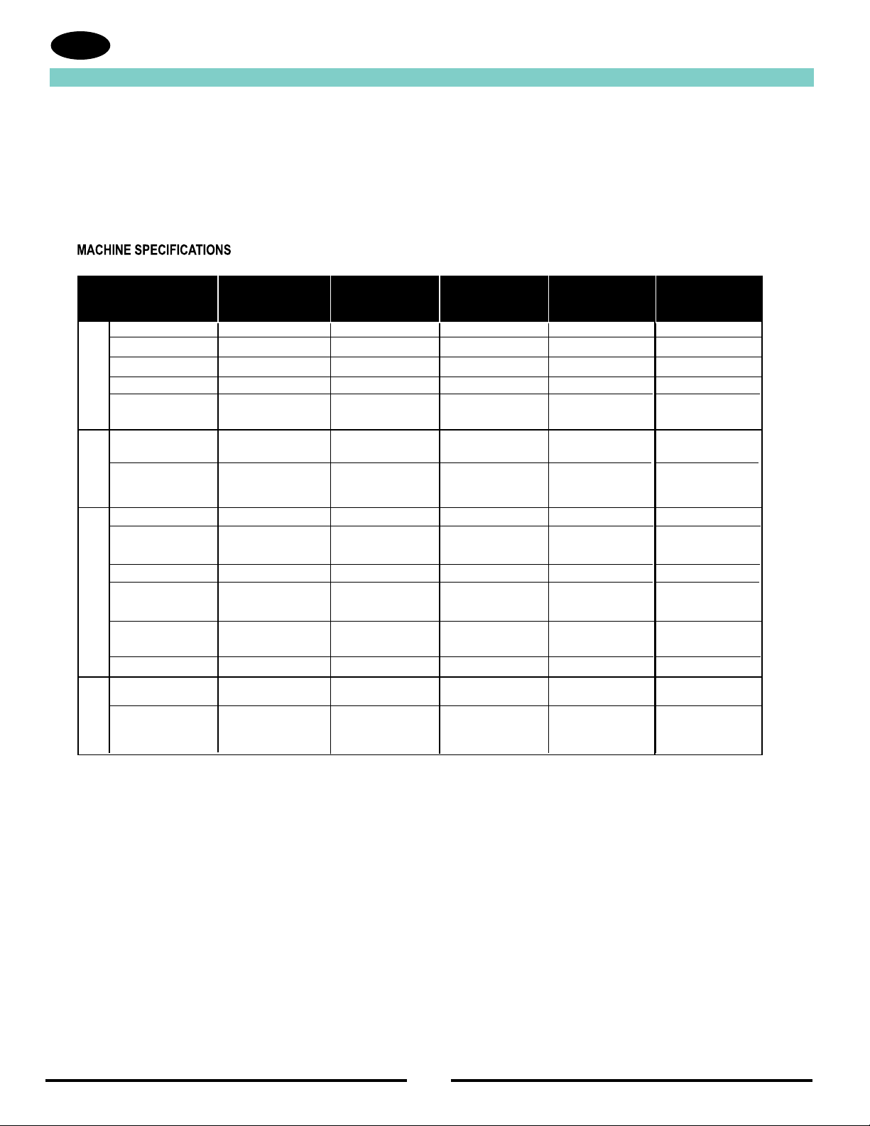
Machine Specifications..................................................................6
Machine Set-Up..........................................................................7-8
Electrical Connection Instructions................................................9
Operating Instructions..................................................................11
Maintenance.........................................................................12
Assembly Drawing..................................................................36-37
Handle Assembly....................................................................38-41
Motor Assembly............................................................................42
Wiring Diagram.......................................................................43-44
EC Declaration of Conformity.......................................................47
Serial Tag.....................................................................................48
READ THIS BOOK
This book has important information for the use and safe operation of this machine. Failure to read this book prior to
operating or attempting any service or maintenance procedure to your American Sanders machine could result in injury
to you or to other personnel; damage to the machine or to other property could occur as well. You must have training in
the operation of this machine before using it. If your operator(s) cannot read this manual, have it explained fully before
attempting to operate this machine.
All directions given in this book are as seen from the operator’s position at the rear of the machine.
***This product is intended for commercial use only***
WARNING!
The Products sold with this Manual contain or may contain chemicals that are known to certain governments (such as the State of
California, as identied in its Proposition 65 Regulatory Warning Law) to cause cancer, birth defects or other reproductive harm. In
certain locations (including the State of California) purchasers of these Products that place them in service at an employment job site
or a publicly accessible space are required by regulation to make certain notices, warnings or disclosures regarding the chemicals that
are or may be contained in the Products at or about such work sites. It is the purchaser’s responsibility to know the content of, and
to comply with, any laws and regulations relating to the use of these Products in such environments. The Manufacturer disclaims any
responsibility to advise purchasers of any specic requirements that may be applicable to the use of the Products in such environments.
In this Operation Manual you will find three statements that you must read and observe to ensure safe operation of this
machine.
DANGER means: Severe bodily injury or death can occur to you or other personnel if the DANGER statements
found on this machine or in this Operation Manual are ignored or are not adhered to. Read and observe
all DANGER statements found in this Operation Manual and on your machine.
WARNING means: Injury can occur to you or to other personnel if the WARNING statements found on your
machine or in the Operation Manual are ignored or are not adhered to. Read and observe all WARNING
statements found in this Operation Manual and on your machine.
CAUTION means: Damage can occur to the machine or to other property if the CAUTION statements found
on your machine or in this Operation Manual are ignored or are not adhered to. Read and observe all
CAUTION statements found in this Operation Manual and on your machine.
Operator Safety Instructions
EN

3
EN
DANGER: Failure to read the Owner’s Manual prior to operating or servicing your American Sanders machine could result in injury to
you or to other personnel; damage to the machine or to other property could occur as well. You must have training in the
operation of this machine before using it. If you or your operator(s) cannot read English, have this manual explained fully
before attempting to operate this machine.
DANGER: A. Sanding/nishing wood oors can create an explosive or combustible environment. Do not operate this machine around
solvents, thinners, alcohol, fuels, oor nishes, wood dust or any other ammable materials. Cigarette lighters, pilot lights,
electrical sparks and all other sources of ignition should be extinguished or avoided. Keep work area well ventilated.
B. Dust generated from sanding wood oors can spontaneously ignite or explode. Promptly dispose of any sanding dust in
a metal container clear of any combustibles. Do not dispose in a re.
DANGER: A. Electrocution could occur if the machine is being serviced while the machine is connected to a power source. Disconnect
the power supply before servicing.
B. Electrocution or re could occur if the machine is being operated with a damaged power cord. Keep the power cord clear
of the pad. Always lift the cord over the machine. Do not move the machine by the power cord.
C.Shock hazard. Do not use the machine if it has been rained on or sprayed with water.
DANGER: To avoid injury keep hands, feet, and loose clothing away from all moving parts on the machine. Disconnect the power cord
before replacing the pad, changing the abrasive, or when servicing. Do not operate the machine unless all guards are in
place. Never leave the machine unattended while connected to a power source.
WARNING: Injury can occur if protective clothing or equipment is not used while sanding. Always wear safety goggles, protective
clothing, and dust mask while sanding.
WARNING: This sander is not to be used on pressure treated wood. Some pressure treated woods contain arsenic and sanding
pressure treated wood produces hazardous dust. Inhaling hazardous dust from pressure treated wood can cause serious
injury or death. Sanding pressure treated wood decks or uneven surfaces can damage the sander which is not covered
under warranty or damage waiver.
WARNING: Any alterations or modications of this machine could result in damage to the machine or injury to the operator or other
bystanders. Alterations or modications not authorized by the manufacturer voids any and all warranties and liabilities.
WARNING: Risk of explosion. Floor sanding can result in an explosive mixture of ne dust and air. Use oor sanding machine only in a
well-ventilated area free from any ame or match.

4
EN

5
EN

6
Introduction
EN
Part No. 07170A 07176A 07180A 07220A
MODEL CE 7 PRO+ SE 7 PRO + SE7 PRO CE7 PRO+
V 120 120 120 230
A 12 12 12 6
W 1.3 kW 1.3 kW 1.3 kW 1.3 kW
Hz 60 60 60 50
Cable 25' 14-3 25' 14-3 NA H05VVF3G
Grey Rubber Grey Rubber 1.5mm sq.
Vibration Exposure 4.9 m/s24.9 m/s24.0 m/s24.9 m/s2
Sound Emissions 91 dB(A) 91 dB(A) 91 dB(A) 91 dB(A)
Pad Speed 3640/3030 rpm 3640/3030 rpm 3640 rpm 3640/3030 rpm
Abrasive (in/mm) 7/178 Hook & loop 7/178 Hook & loop 7/178 Hook & loop 7/178 Hook & loop
or 7/8" Mounting hole or 7/8" Mounting hole or 7/8" Mounting hole or 7/8" Mounting hole
Air Flow (CFM) 136 136 136 136
Effective Reach 5.24/13.31 3.76/9.55 3.76/9.55 5.24/13.31
@ 3.5" Height (in/cm)
Dimensions (in/cm) 16.61x11.78x12.69 / 15.02x11.78x12.68 / 15.02x11.78x12.68 / 16.6x11.78x12.69 /
42.2x29.932.2 38.2x29.9x32.2 38.2x29.9x32.2 42.2x29.9x32.2
Weight (lbs./kg) 36.5 / 16.6 35.5 / 16.1 33.0 / 15.0 36.5 / 16.6
Weight (lbs./kg) 47.5 / 21.6 46.5 / 21.1 39.5 / 18.0 47.5 / 21.6
Dimensions (in/cm) 20x17.25x22.75 / 20x17.25x22.75 / 20x17.25x22.75 . 20x17.25x22.75 /
51x43.8x57.8 51x43.8x57.8 51x43.8x57.8 51x43.8x57.8
Shipping Performance Environmental Electrical
Part No. 07170A 07176A 07180A 07175A
MODEL CE 7 PRO+ SE 7 PRO + SE7 PRO CE7 PRO
V 120 120 120 120
A 12 12 12 12
W 1.3 kW 1.3 kW 1.3 kW 1.3 kW
Hz 60 60 60 60
Cable 25' 14-3 25' 14-3 NA NA
Grey Rubber Grey Rubber
Vibration Exposure 4.9 m/s24.9 m/s24.0 m/s24.0 m/s2
Sound Emissions 91 dB(A) 91 dB(A) 91 dB(A) 91 dB(A)
Pad Speed 3640/3030 rpm 3640/3030 rpm 3640 rpm 3640 rpm
Abrasive (in/mm) 7/178 Hook & loop 7/178 Hook & loop 7/178 Hook & loop 7/178 Hook & loop
or 7/8" Mounting hole or 7/8" Mounting hole or 7/8" Mounting hole or 7/8" Mounting hole
Air Flow (CFM) 136 136 136 136
Effective Reach 5.24/13.31 3.76/9.55 3.76/9.55 5.24/13.31
@ 3.5" Height (in/cm)
Dimensions (in/cm) 16.61x11.78x12.69 / 15.02x11.78x12.68 / 15.02x11.78x12.68 / 16.6x11.78x12.69 /
42.2x29.932.2 38.2x29.9x32.2 38.2x29.9x32.2 42.2x29.9x32.2
Weight (lbs./kg) 36.5 / 16.6 35.5 / 16.1 33.0 / 15.0 34.0 /15.5
Weight (lbs./kg) 47.5 / 21.6 46.5 / 21.1 39.5 / 18.0 40.5 / 18.4
Dimensions (in/cm) 20x17.25x22.75 / 20x17.25x22.75 / 20x17.25x22.75 . 20x17.25x22.75 /
51x43.8x57.8 51x43.8x57.8 51x43.8x57.8 51x43.8x57.8
Shipping Performance Environmental Electrical
INTRODUCTION AND MACHINE SPECIFICATIONS
The CE and SE 7 models were designed for the sanding of oors in places where larger machines are not practical or
cannot reach. They are suitable for roughing and nishing sanding of laminated or parquet oors. They can be used for a
wide variety of wood types including pine, oak or maple. Their greater reach allows them to be used under obstacles or
endings of bases of furniture (toe-kicks). In both models, a 7" x 7/8" (17.78 x 2.2 cm) mounting hole or a 7" (17.78 cm) Hook
and Loop abrasive disc can be used.

Figure 1.1
Figure 2.1
Figure 2.2
7
Machine Set-Up
EN
UNCRATE THE MACHINE
When the machine is delivered, carefully inspect the shipping
carton and the machine for damage. If damage is evident, save
the shipping carton so that it can be inspected. Contact the
American Sanders Customer Service Department.
7" (17.78 cm) Hook and Loop
MACHINE SET-UP
Fig. 1.1 OPERATING HANDLE
The operating handle provides control and comfort to the sanding
experience (all models). On models 07170A and 07176A, the handles
may be set to a greater height depending on preference. Remove the
4 screws securing the handle to the machine. Raise the handle until
the holes align then reinstall the 4 screws.
Fig. 2.1, 2.2 ABRASIVE DRIVER
The unit will accept either 7″ (17.78 cm) hook and loop or 7″ x 7/8″
(17.78 x 2.2 cm) center hole abrasive disc. Motion is delivered to the
abrasive through a replaceable spring steel sanding disc (11226A)
having a medium hook surface (39864A). The unique geometry
provides a at nish and smooth sanding experience, reducing
objectionable scratches. The unit is equipped with a retaining screw,
washer, and onboard wrench for use with 7″ x 7/8″ (17.78 x 2.2 cm)
abrasive. When installing abrasive disc, take care to center disc on
driver.
NOTE: When using 7″ x 7/8″ (17.78 x 2.2 cm) abrasive, hold the
sanding disc while tightening the retaining screw. Do not over tighten
or removal will be difcult.
To avoid injuring the hook surface on the driver when sanding thick
paint, varnish or wax, it is recommended you stack two discs on the
driver using a course open coat abrasive.
7"x 7/8" (17.78 x 2.2 cm) Mounting Hole

8
Machine Set-Up
EN
Figure 3.1
Figure 3.2
Install the dust bag by pressing the end onto the
exhaust tube until the ring locks into the groove.
A
2" (5 cm) Hose
from vacuum
system (not
included)
1.5" (3.8 cm)
Hose from
vacuum system
(not included)
D
B
C
Exhaust Tube
(30563A) 2" (5 cm) Tube x 1.5" (3.8 cm) hose adaptor
FIG. 3.1, 3.2 DUST MANAGEMENT
This sanding machine is designed to be operated with a remote vacuum
dust collection system or with the included dust bag.
PREPARING REMOTE VACUUM DUST COLLECTION SYSTEMS
To prepare the machine for remote vacuum dust collection systems that
have a 2″ (5 cm) hose end, follow this procedure:
1. Install 2″ (5 cm) hose end (gure 3.1, A) directly over the exhaust
tube (gure 3.1, B).
2. The exhaust tube can be rotated for optimum convenience.
To prepare the machine for remote vacuum dust collection systems that
have a 1-1/2″ (3.8 cm) hose end, follow this procedure:
1. Install the optional 2″ x 1-1/2″ (5 x 3.8 cm) hose end adaptor (Part
No. 30563A) (gure 3.1, C) over the exhaust tube (gure 3.1, B).
2. Insert 1-1/2″ (3.8 cm) hose end (gure 3.1, D) into the adaptor
(gure 3.1, C).
NOTE: Start the remote vacuum collection system before
operation.
PREPARING TO USE THE INCLUDED DUST BAG
To prepare the machine for use with the included dust bag (Part No.
53544C), follow this procedure:
1. Install the dust bag by pressing the end onto the exhaust tube until
the ring locks into the groove (gure 3.2). This is best done by
pressing on the back of the bag opening with the palm of your hand.
2. The exhaust tube can be rotated for optimum convenience.
3. To remove the dust bag from the exhaust tube, pry up the end of
the bag opening to partially release the internal rib from the groove,
then pull.
4. To empty the dust bag, unzip the disposal ap and force contents
out by inverting the bag.
NOTE: For best results, empty frequently. Follow all warnings
posted in this manual and on the dust bag.

9
Electrical Connection Instructions
EN
Figure 4.1
Figure 4.2
Figure 5.1
FIG. 4.1 ELECTRICAL CONNECTION
The unit is equipped with a grounding NEMA L5-15P locking plug
(g 4.1). Connection to an electrical source is made through an
extension cord (optional 42300A). Connect the plug on the extension
cord to a wall outlet matching one of the two shown (g. 4.2). Plug the
appliance into the matching connector then twist clockwise until the
cables are locked.
NOTE: The extension cord must be sized to a minimum of 14 AWG
2 conductor with ground not exceeding 50' (15.24 m) in length and
have for ends a NEMA 5-15P plug and NEMA L5-15R connector.
An extension cord sized smaller than 14 AWG or greater than
50' (15.24 m) in length will overheat and potentially cause a re.
DANGER!
This appliance must be grounded. Should an electrical malfunction
occur, the grounding conductor provides a path to harmful charge.
Do not connect this appliance to any other wall outlet than one of
those shown in g. 4.2. Consult an electrician if there is reason to
doubt that the wall outlet is not wired correctly. Do not remove pin
on the extension cord. Do not use the appliance with a damaged
cord or connectors.
FIG. 5.1 CONTROLS
All controls are conveniently located on the handle providing comfort
and security. The master control switch (all models) is activated with
a rocking motion as shown in gure 5.1a. The switch will remain
activated until it is deliberately deactivated or if there is a loss of
power. The speed control switch (models 07170A and 07176A only)
varies the abrasive disc speed (g. 5.1b). The switch is operated with
a rocking motion. The switch will remain in a particular setting until it
is deliberately changed.
A
B
LOW HIGH
ONOFF

10
Machine Set-Up
EN
Figure 6.1
FIG. 6.1 SANDING PATTERN
The unit is factory set to sanding pattern 2.
1.
To alter the sanding pattern to 1:
a.) Loosen the locknuts on A & B.
b.) Turn stem A counter clockwise and stem B clockwise in
1/4 turn increments until the desired pattern is achieved.
c.) Tighten locknuts on A & B.
2. To alter the sanding pattern to 3:
a.) Loosen the locknuts on A & B.
b.) Turn stem A clockwise and stem B counter clockwise until
the desired pattern is achieved.
c.) Tighten locknuts on A & B.
3. To move the pattern to the outer edge of the sanding disc:
a.) Loosen locknuts on A & B.
b.) Turn stem A & B clockwise in 1/4 turn increments until the
desired pattern is achieved.
c.) Tighten locknuts on A & B.
4. To move the pattern away from the edge on the sanding disc:
a.) Loosen locknuts A & B.
b.) Turn stems A & B counter clockwise until the desired
pattern is achieved.
c.) Tighten locknuts on A & B.
FIG. 6.2 RESET CASTER SETTING
1.
To reset caster to factory setting:
a.) Loosen the locknuts on A & B (Fig. 6.1).
b.) Rotate stem with large at blade screw driver to
distance shown.
c.) Tighten locknuts on A & B.
AB
123
Figure 6.2
HEIGHT MODEL
.772 (19.61) CE 7
.872 (21.01) SE7

11
Operating Instructions
EN
Figure 7.1
Figure 7.2
Operating Instructions
1. Install the abrasive disc.
2. Connect the dust management system.
3. Connect the extension cord to a wall outlet and then to the
machine.
4. Raise the sanding disc from the surface then activate the
master control switch.
5. Lower the sanding disc to the surface and begin sanding.
Do not press down on the handle while sanding. Doing so
will promote objectionable scratches and an uneven nish.
Depending on technique and desired results, use one or a
combination of the two methods shown in gures 7.1 and 7.2.
6. For optimum dust management performance when using the
included dust bag (53544C), empty frequently. Do not overll.
Empty when dust reaches full line.
WARNING!
Follow all instructions found in this manual and on the dust bag
pertaining to the safe storage and handling of sanding dust.

12
Maintenance
EN
Figure 8.1
Figure 8.2
Wear Indicator
DRIVE BELT
Replace the drive belt every 1000 hours or on the 3rd set of carbon
brushes. Replace lower motor bearing at every drive belt change
interval. Replace upper motor bearing every 1500 hours.
MOTOR BEARINGS
Replace lower motor bearing at every drive belt change interval.
Replace upper motor bearing every 1500 hours.
ABRASIVE DRIVER BEARINGS
The bearings should not need replacement for the life of the machine.
CARBON BRUSHES (FIGURES 8.1 AND 8.2)
Replace the carbon brushes (see gure 8.1) every 350-400 hours
depending on use. Replace both brushes if either has worn to the
wear indicator (see gure 8.2). Have the commutator turned and
undercut every 3rd replacement.

LEA ESTE MANUAL
Este manual contiene información importante acerca del uso y la seguridad de la máquina. Si no lee el manual antes de utilizar su
máquina American Sanders o de intentar realizar los procedimientos de reparación o mantenimiento de la misma, usted o el resto
del personal podrían sufrir lesiones; asimismo, podrían producirse daños a la máquina o a otras propiedades. Antes de utilizar la
máquina, es necesario recibir la capacitación adecuada en la operación de la misma. Si el operador de la máquina no sabe leer en
español, explíquele el manual exhaustivamente antes de que intente utilizarla.
Todas las indicaciones incluidas en este manual se ofrecen desde la posición del operador en la parte posterior de la máquina.
ADVERTENCIA!
Los Productos a la venta en este Manual contienen, o pueden contener, productos químicos reconocidos por algunos gobiernos (como el Estado de
California, según lo indica en su Proposición 65, Ley de Advertencia Regulatoria) como causantes de cáncer, defectos de nacimiento u otros daños
reproductivos. En algunas jurisdicciones (incluido el Estado de California), los compradores de estos Productos que los coloquen en servicio en un
emplazamiento laboral o en un espacio de acceso público tienen la obligación regulatoria de realizar determinados avisos, advertencias o divulgaciones
respecto de los productos químicos contenidos o posiblemente contenidos en los Productos utilizados en tal lugar. Es la responsabilidad del
comprador
conocer y cumplir con todas las leyes y reglamentaciones relacionadas con el uso de estos Productos en tales entornos. El Fabricante niega toda
responsabilidad de informar a los compradores sobre requisitos especícos que pueden regir el uso de los Productos en tales entornos.
ES
CONTENIDO DE ESTE LIBRO
Instrucciones de seguridad para el operador ..............................14-15
Introducción y especicaciones de la máquina ................................16
Instalación de la máquina............................................................17-20
Operación de la máquina ................................................................. 21
Mantenimiento ................................................................................. 22
Sección II Repuestos y manual de servicio
Plano de montaje #1......................................................................... 36
Listado de piezas de montaje #1................................................. 37
Plano de montaje #2......................................................................... 38
Listado de piezas de montaje #2................................................. 39
Plano de montaje / Listado de piezas de montaje #3....................... 40
Plano de cableado............................................................................ 41

PELIGRO signica: Usted u otras personas pueden estar expuestos a sufrir lesiones personales, inclusive la
muerte si las indicaciones de PELIGRO que se encuentran en esta máquina o en el manual
de instrucciones se ignoran o no se tienen en cuenta. Lea y respete todas las indicaciones
de PELIGRO que se encuentran en el manual de instrucciones y en la máquina.
ADVERTENCIA signica: Usted u otras personas pueden estar expuestos a sufrir lesiones personales, si las
indicaciones de ADVERTENCIA que se encuentran en esta máquina o en el manual de
instrucciones se ignoran o no se tienen en cuenta. Lea y respete todas las indicaciones de
ADVERTENCIA que se encuentran en el manual de instrucciones y en su máquina.
PRECAUCIÓN signica:
La máquina u otros bienes pueden sufrir daños materiales si las indicaciones de PRECAUCIÓN
que se encuentran en la máquina o en el manual de instrucciones se ignoran o no se
tienen en cuenta. Lea y respete todas las indicaciones de PRECAUCIÓN que se
encuentran en el manual de instrucciones y en la máquina.
Instrucciones De Seguridad Para El Operador
ES
14

ES
15

16
Introducción
ES
INTRODUCCIÓN Y ESPECIFICACIONES DE MÁQUINA
Los modelos CE y SE 7 se diseńaron para el lijado de los pisos de aquellos lugares para los que las máquinas de mayor tamańo
no resultan prácticas o no tienen alcance. Son adecuados para el lijado de desbaste y acabado de pisos alistonados o de parquet.
Pueden usarse para una amplia variedad de tipos de madera entre ellas, pino, roble o arce. Su mayor alcance permite usarlos
debajo de obstáculos o terminaciones de bases de muebles (toe-kicks). En ambos modelos se puede utilizar un oricio de montaje
de 7” x 7/8” o un disco abrasivo de apertura y cierre rápido (Hook and Loop) de 7”.
Envio Rendimiento Ambientales Eléctricas
N° de pieza 07170A 07176A 07180A 07175A 07220A
Modelo CE 7 PRO+ CE 7 PRO + SE7 PRO + SE7 PRO CE7 PRO+
V 120 120 120 120 230
A 12 12 12 12 12
W 1,3 kW 1,3 kW 1,3 kW 1,3 kW 1,3 kW
Hz 60 60 60 60 50
Cable 25' (7.62 m) 14-3 25' (7.62 m) 14-3 NA NA H05VVF3G
Caucho gris Caucho gris 1.5mm sq.
Exposición a las 4,9 m/s
2
4,9 m/s
2
4,0 m/s
2
4,0 m/s
4,9 m/s
2
vibraciones
Emisiones sonoras 91 dB(A) 91 dB(A) 91 dB(A) 91 dB(A) 91 dB(A)
Velocidad del disco 3640/3030 rpm 3640/3030 rpm 3640 rpm 3640 rpm 3640/3030 rpm
Disco abrasivo 7/178 de apertura y cierre 7/178 de apertura y cierre
7/178 de apertura y cierre
7/178 de apertura y cierre 7/178 de apertura y cierre
(pulgada/mm) rápido (Hook and Loop) u rápido (Hook and Loop) u
rápido (Hook and Loop ) u
rápido (Hook and Loop) u rápido (Hook and Loop) u
oricio de montaje de 7/8" oricio de montaje de 7/8"
oricio de montaje de 7/8"
oricio de montaje de7/8" oricio de montaje de7/8"
Caudal de aire (CFM) 136 136 136 136 136
Alcance efectivo 5,24/13,31 3,76/9,55 3,76/9,55 5,24/13,31 5,24/13,31
a 3,5" de altura
(pulgada/cm)
Dimensiones 16,61x11,78x12,69 / 15,02x11,78x12,68 / 15,02x11,78x12,68 / 16,6x11,78x12,69 / 16,6x11,78x12,69 /
(pulgada/cm) 42,2x29,9x32.2 38,2x29,9x32,2 38,2x29,9x32,2 42,2x29,9x32,2 42,2x29,9x32,2
Peso (libras/kg) 36,5 / 16,6 35,5 / 16,1 33,0 / 15,0 34,0 /15,5 36,5 / 16,6
Peso (libras/kg) 47,5 / 21,6 46,5 / 21,1 39,5 / 18,0 40,5 / 18,4 47,5 / 21,6
Dimensiones 20x17,25x22,75 / 20x17,25x22,75 / 20x17,25x22,75 . 20x17,25x22,75 / 20x17,25x22,75 /
(pulgada/cm) 51x43,8x57,8 51x43,8x57,8 51x43,8x57,8 51x43,8x57,8 51x43,8x57,8
ESPECIFICACIONES DE LA MAQUINA

17
Figura 1.1
Figure 2.1
Figura 2.2
Oricio de montaje de 7" x 7/8" (17.78 x 2.2 cm)
CONFIGURACIÓN DE LA MÁQUINA
Fig. 1.1 EMPUŃADURA DE FUNCIONAMIENTO
La empuñadura de funcionamiento permite controlar el lijado y
resulta muy cómoda (en todos los modelos). En los modelos 07170A
y 07176A, las empuñaduras pueden regularse para lograr una
mayor altura según se preera. Extraiga los 4 tornillos que sujetan
la empuñadura a la máquina. Eleve la empuñadura hasta que los
oricios se alineen y luego coloque nuevamente los 4 tornillos.
FIG. 2.1, 2.2 MOTOR DEL DISCO ABRASIVO
La unidad puede usarse con un disco abrasivo de apertura y
cierre rápido de 7″ (17.78 cm) o un oricio de centrado de
7″ x 7/8″ (17.78 x 2.2 cm). El disco abrasivo se activa a través de
un disco de lijado de acero de resorte reemplazable (11226A) que
tiene una supercie de enganche medio (39864A). Su conguración
exclusiva permite lograr un acabado plano y un lijado suave,
lo cual reduce la posibilidad de rayas no deseadas.
La unidad está equipada con un tornillo de retención, una arandela
y una llave de a bordo que se usa con el disco abrasivo de
7″ x 7/8″ (17.78 x 2.2 cm). Cuando instale el disco abrasivo,
debe tomar la precaución de centrarlo sobre el motor.
NOTA: Cuando use el disco abrasivo de 7″ x 7/8″ (17.78 x 2.2 cm),
sostenga el disco de lijado mientras ajusta el tornillo de retención. No
lo ajuste de forma excesiva o resultará difícil extraerlo.
Para evitar dańar la supercie del enganche del motor al lijar pintura
espesa, barniz o cera, se recomienda apilar dos discos en el motor
usando granos ásperos y abiertos.
Apertura y cierre rápido de 7" (17.78 cm)
INSTALACIÓN DE LA MÁQUINA
ES
DESCRIBA LA MAQUINA
Cuando se entregue la máquina, inspeccione cuidadosamente
la caja de envío y la máquina en busca de daños. Si el daño
es evidente, guarde la caja de envío para que pueda ser
inspeccionada. Póngase en contacto con el Departamento de
Servicio al Cliente de Estados Unidos.

18
INSTALACIÓN DE LA MÁQUINA
ES
A
MANGUERA DE
2" (3.8 cm) DEL
SISTEMA DE
ASPIRACIÓN (NO
INCLUIDO)
MANGUERA DE 1.5"
(3.8 cm) DEL SISTEMA
DE ASPIRACIÓN (NO
INCLUIDO)
D
B
C
TUBO DE ESCAPE
30563A TUBO DE 2" (5 cm) X
ADAPTADOR DE MANGUERA DE 1.5" (3.8 cm)
Figura 3,1
Figura 3.2
INSTALE LA BOLSA DE RECOLECCIÓN DE POLVO PRESIONANDO
EL EXTREMO DEL TUBO DE ESCAPE HASTA QUE EL ANILLO
ENCAJE DENTRO DE LA RANURA.
FIG. 3.1, 3.2 CONTROL DE POLVO
Esta lijadora está diseńada para utilizarse con un sistema colector de
polvo remoto mediante vacío o con la bolsa de polvo incluida.
Preparación de los sistemas colectores de polvo remotos mediante vacío
Si desea preparar la máquina para sistemas colectores de polvo remotos
mediante vacío que tengan un extremo de manguera de 2″ (5 cm), siga
este procedimiento:
1. Instale e extremo de manguera de 2″ (5 cm) (gura 3.1, A)
directamante sobre el tubo de escape (gura 3.1, B).
2. El tubo de escape puede girarse para mayor comodidad.
Si desea preparar la máquina para sistemas colectores de polvo remotos
mediante vacío que tengan un extremo de manguera de 1-1/2″ (3.8 cm),
siga este procedimiento:
1. Instale el adaptador del extremo de manguera de 2″ x 1-1/2″
(5 cm x 3.8 cm) (No de pieza 30563A) (gura 3.1, C) sobre el tubo
de escape (gura 3.1, B).
2. Inserte el extremo de manguera de 1-1/2″ (3.8 cm) (opcional)
(gura 3.1, D) en el adaptador (gura 3.1, C).
NOTA: Ponga en marche el sistema colector remoto mediante vacío
antes de encender la máquina.
PREPARACIÓN PARA USAR LA BOLSA DE POLVO INCLUIDA
Si desea preparar la máquina para su uso con la bolsa de polvo incluida
(No de pieza 53544C), siga este procedimiento.
1. Instale la bolsa de recolección de polvo presionando el extremo del
tubo de escape hasta que el anillo encaje dentro de la ranura (gura
3.2). El mejor modo de hacer esto es presionando la parte posterior
de la abertura de la bolsa con la palma de su mano.
2. El tubo de escape puede girarse para mayor comodidad.
3. Para retirar la bolsa de polvo del tubo de escape, haga palanca
hacia arriba en el extremo de la abertura de la bolsa para liberar
parcialmente el saliente interno de la ranura, y después tire.
4. Para vaciar la bolsa de polvo, abra la aleta de vaciado y saque sus
contenidos dando la vuelta a la bolsa.
NOTA: Para lograr los mejores resultados, vacíe frecuentemente.
Siga todas las advertencias incluidas en el manual y en la bolsa de
polvo.

19
INSTALACIÓN DE LA MÁQUINA
ES
Figura 4.1
Figura 4.2
Figura 5.1
A
B
15A 125V
Conexión a tierra de 2
polos y 3 conductores
Conguración NEMA 5-15R
20A 125V
Conexión a tierra de 2
polos y 3 conductores
Conguración NEMA 5-20R
LOW (bajo) HIGH (alto)
OFF (apagado) ON (encendido)
30563A TUBO DE 2" (5 cm) X
ADAPTADOR DE MANGUERA DE 1.5" (3.8 cm)
FIG. 4.1 CONEXIÓN ELÉCTRICA
La unidad está equipada con un enchufe de sujeción NEMA L5-15P
de conexión a tierra (g. 4.1). La conexión al suministro de energía
eléctrica se realiza a través de un alargador (opcional 42300A). Conecte
el enchufe del alargador a una toma de corriente de la pared igual a una
de las dos que se muestran más arriba (g. 4.2). Enchufe el artefacto
al conector correspondiente y luego gírelo en sentido de las agujas del
reloj hasta que los cables queden sujetos.
NOTA: El alargador debe tener como mínimo un conductor 14 AWG
2 cuya conexión a tierra no supere 50' (15.24 m) de longitud con un
enchufe NEMA 5-15P y un conector NEMA L5-15R en el extremo. Si
el alargador tiene un conductor de menos de 14 AWG o de más de 50'
(15.24 m) de longitud se sobrecalentará y puede ocasionar un incendio.
PELIGRO!
Este artefacto debe conectarse a tierra. Si se produjese un problema
de funcionamiento eléctrico, el conductor de conexión a tierra brinda un
paso para la corriente perjudicial. Este artefacto sólo debe conectarse
a una toma de corriente de pared igual a una de las que aparecen en
la g. 4.2. Consulte a un electricista si tiene motivos para pensar que
es posible que la toma de corriente de la pared no esté conectada
correctamente. No extraiga la clavija del alargador. No utilice el artefacto
con cables o conectores dañados.
FIG. 5.1 MANDOS
Todos los mandos están ubicados convenientemente en la empuñadura
lo cual brinda comodidad y seguridad. El interruptor de mando principal
(en todos los modelos) se activa mediante un vaivén como se indica
en la gura 5.1a. El interruptor permanecerá activado hasta que se lo
desactive de forma intencional o si existe una pérdida de potencia. El
interruptor de mando de la velocidad (en los modelos 07170A y 07176A
solamente) varía la velocidad del disco abrasivo (g. 5.1b). El interruptor
se opera con un movimiento de vaivén. El interruptor permanecerá en un
ajuste en particular hasta que se lo cambie de forma intencional.

20
INSTALACIÓN DE LA MÁQUINA
ES
Figura 6.1
FIG. 6.1 PATRÓN DE LIJADO
La unidad está congurada de fábrica con el patrón de lijado 2.
1. Para cambiar el patrón de lijado a 1:
a.) Aoje las tuercas de seguridad de A y B.
b.) Gire el vástago A en sentido contrario a las agujas del
reloj y el vástago B en sentido de las agujas del reloj con
incrementos de 1/4 de giro hasta lograr el patrón deseado.
c.) Ajuste las tuercas de seguridad de A y B.
2. Para cambiar el patrón de lijado a 3:
a.) Aoje las tuercas de seguridad de A y B.
b.) Gire el vástago A en sentido de las agujas del reloj y el
vástago B en sentido contrario a las agujas del reloj hasta
lograr el patrón deseado.
c.) Ajuste las tuercas de seguridad de A y B.
3. Para desplazar el patrón hasta el borde exterior del disco de
lijado:
a.) Aoje las tuercas de seguridad de A y B.
b.) Gire el vástago A y B en sentido de las agujas del reloj
con incrementos de 1/4 de giro hasta lograr el patrón
deseado.
c.) Ajuste las tuercas de seguridad de A y B.
4. Para alejar el patrón del borde del disco de lijado:
a.) Aoje las tuercas de seguridad de A y B.
b.) Gire el vástago A y B en sentido contrario a las agujas del
reloj hasta lograr el patrón deseado.
c.) Ajuste las tuercas de seguridad de A y B.
5. Para regresar el patrón al ajuste de fábrica, consulte la
ilustración incluida en la lista de piezas 1 de la página 34.
AB
123
This manual suits for next models
7
Table of contents
Languages:
Other American Sanders Edger manuals
Popular Edger manuals by other brands

Homelite
Homelite UT13140 Operator's manual

Powermate
Powermate King Pro P-WLE-1639-E Illustrate parts book

Little Wonder
Little Wonder BedShaper Owner's manual and safety instructions

Maruyama
Maruyama E300S Owner's/operator's manual

Texas Equipment
Texas Equipment EC1400 user manual

Robin
Robin BE26 instruction manual

Echo
Echo PE-266S Operator's manual

Husqvarna
Husqvarna 327ES Operator's manual

Nidek Medical
Nidek Medical ME-1000 Service manual

GreenWorks
GreenWorks 60V Pro Series Operator's manual

Textron
Textron JACOBSEN DE160 Owner/Operator's Manual & Illustrated Parts List

Nidek Medical
Nidek Medical LE-9000SX Operator's manual