18-BC53D1-4 3
Installer’s Guide
After the brazing operation of refrigerant lines to both the outdoor
and indoor unit is completed, the field brazed connections must be
checked for leaks. Pressurize through the service valve ports, the
indoor unit and field refrigerant lines with dry nitrogen to 350-400 psi.
Use soap bubbles or other leak-checking methods to see that all field
joints are leak-free! If not, release pressure; then repair!
SYSTEM EVACUATION
NOTE:
Since the outdoor unit has a refrigerant charge, the gas and liquid
line valves must remain closed.
1. Upon completion of leak check, evacuate the refrigerant lines
and indoor coil before opening the gas and liquid line valves.
2. Attach appropriate hoses from manifold gauge to gas and liquid
line pressure taps.
NOTE:
Unnecessary switching of hoses can be avoided and complete
evacuation of all lines leading to sealed system can be accom-
plished with manifold center hose and connecting branch hose to
a cylinder of HCFC-22 and vacuum pump.
3. Attach center hose of manifold gauges to vacuum pump.
4. Evacuate until the micron gauge reads no higher than 350 microns.
5. Close off valve to vacuum pump and observe the micron gauge.
If gauge pressure rises above 500 microns in one (1) minute,
then evacuation is incomplete or system has a leak.
6. If vacuum gauge does not rise above 500 microns in one (1)
minute, the evacuation should be complete.
7. Blank off vacuum pump and micron gauge, close valves on
manifold gauge set.
NOTE:
DO NOT VENT REFRIGERANT INTO THE ATMOSPHERE.
NOTE:
A 3/16" Allen wrench is required to open liquid line service valve.
A 1/4" Open End or Adjustable wrench is required to open gas line
valve. A 3/4" Open End wrench is required to take off the valve
stem cap.
8. The liquid line shut-off valve can now be opened. Remove shut-
off valve cap. Fully insert hex wrench into the stem and
backout counterclockwise until valve stem just touches rolled
edge (approximately five [5] turns) observing WARNING
statement on page 2. See Figure 3.
9. Replace liquid service pressure tap port cap and valve stem cap.
These caps MUST BE REPLACED to prevent leaks. Replace
valve stem and pressure tap cap finger tight, then tighten an
additional 1/6 turn.
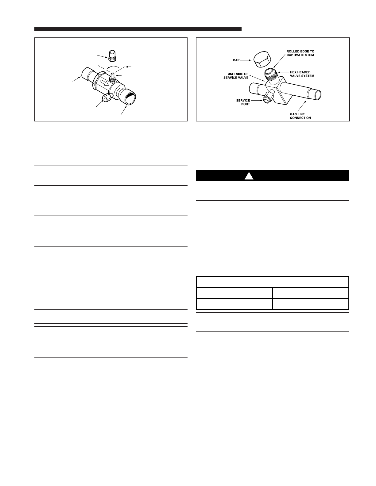
10. The gas valve can now be opened. For a ball type gas valve, open
the gas valve by removing the shut-off valve cap and turning the
valve stem 1/4 turn counterclockwise, using 1/4" Open End or
Adjustable wrench. See Figure 4. For brass gas line service valve
opening, follow 8 and 9 above. See Figure 5.
11. The gas valve is now open for refrigerant flow. Replace valve
stem cap to prevent leaks. Again, these caps MUST BE
REPLACED to prevent leaks. Replace valve stem and
pressure tap cap finger tight, then tighten an additional
1/6 turn. See Figure 4.
If refrigerant lines are longer than fifteen (15) feet and/or a different
size than recommended, it will be necessary to adjust system
refrigerant charge upon completion of installation. See unit Service
Facts.
E. ELECTRICAL CONNECTIONS
WARNING
!
When installing or servicing this equipment, ALWAYS exercise
basic safety precautions to avoid the possibility
of electric shock.
1. Power wiring and grounding of equipment must comply with
local codes.
2. Power supply must agree with equipment nameplate.
3. Install a separate disconnect switch at the outdoor unit.
4. Ground the outdoor unit per local code requirements.
5. Provide flexible electrical conduit whenever vibration transmis-
sion may create a noise problem within the structure.
6. The use of color coded low voltage wire is recommended to
simplify connections between the outdoor unit, the
ComfortLink™ II control and the indoor unit.
Table 1 – NEC Class II Control Wiring
CAP 1/4 TURN ONLY
COUNTERCLOCKWISE
FOR FULL OPEN
POSITION
VALVE STEM
GAS LINE CONNECTION
UNIT SIDE
OF VALVE
PRESSURE TAP PORT
GAS LINE BALL SERVICE VALVE
4GAS LINE SERVICE VALVE
5
NOTE:
The maximum total cable length for the entire Comfort Control
communicating system is 500 ft. 18 AWG.
7. Mount the ComfortLink™ II control in accordance with
instruction included with the ComfortLink™ II control.
Wire per appropriate hook-up diagram (included in these
instructions).
F. DEFROST CONTROL
The demand defrost control measures heat pump outdoor ambient
temperature with a sensor located outside the outdoor coil. A second
sensor located on the outdoor coil is used to measure the coil
temperature. The difference between the ambient and the colder coil
temperature is the difference or delta-T measurement. This delta-T
measurement is representative of the operating state and relative
capacity of the heat pump system. By measuring the change in
delta-T, we can determine the need for defrost. The coil sensor also
serves to sense outdoor coil temperature for termination of the
defrost cycle.
FAULT IDENTIFICATION
A fault condition is indicated by the fault LED on the control board
inside the heat pump control box.
In normal operation, the status LED will flash once each second. If
the light is flashing more than once per second or not at all, refer to
the service manual for that unit.
ComfortLink™ II Control Wiring
WIRE SIZE MAX. WIRE LENGTH
18 AWG 250 FT