SEQUENCE OF OPERATION
Heat Pump -- General
Operation of the unit heating and cooling cycles is automatic when
the system is in the HEAT or COOL functions. (The optional
automatic changeover thermostat, when in the AUTO position,
automatically changes to heat or cool with an appropriate room
temperature change.) The fan switch can be placed in the ON
position, causing continuous indoor fan operation. The fan switch
may also be placed in the AUTO position causing fan operation to
coincide with heating or cooling run cycles.
Cooling Mode
With the disconnect in the ON position, current is supplied to the
sump heater and control transformer. The sump heater supplies
heat to the compressor to prevent liquid refrigerant from accumulat-
ing in the compressor during the off cycle.
The thermostat temperature switch (TSC-1) closes completing the
24 volt circuit from terminal "R" to terminal "O" energizing the
switchover valve solenoid coil (SC). (Nothing else occurs.)
Second Stage Cooling (after a 0.7°Fto 1.5°F temperature rise): The
thermostat temperature switch (TSC=2) closes completing the 24
volt circuit from terminal "R" to terminal "Y" energizing the compres-
sor contactor (MS) and to terminal "G" to energize the fan relay (F).
The MS-1 and MS-2 contacts close simultaneously energizing the
compressor,and outdoor fan motor. The F=I contact closes and
energizes the indoor fan motor. When the (TSC=2) switch closes, the
cooling anticipator is bypassed.
Heating Mode
The thermostat heating switch (TSH-1) closes completing the 24 volt
circuit from terminal "R" to terminal "Y" energizing the compressor
contactor and to terminal "G" to energize the fan relay (F). When
(TSH-1) closes, the heat anticipator (HA)is energized. (The heat
anticipator provides heat to the thermostat bimetal during operation
of the heat pump or resistance heat cycle. The switchover valve (SO)
is not energized due to the voltage drop across the heat anticipator.)
The MS-1 and MS=2 contacts close simultaneously and energize the
compressor,and the outdoor fan motor. At the same time, the F=I
contacts close and energize the indoor fan motor and the F=2
contacts provide a fan interlock for the heater control circuit
Second Stage Heating (after a 0.7°F to 1.5° F temperature drop):
The thermostat heating switch TSH-2 closes and completes a 24 volt
circuit from terminal "R" to terminals "W" and "U" which are bussed
together and thereby energizes the blue light on the thermostat.
Emergency Heat
Positioning the emergency resistance heat switch (RHS) in the
thermostat to the ON position will de-energize the refrigerant system
and the supplementary heat will come on through the second stage
heating contact (TSH-2) of the thermostat. Prior to this, the first
stage heating contact (TSH-1) would have closed the circuit to the
indoor blower, which will continue to run through the emergency heat
cycle and will stop when TSH-1 is satisfied and opens. A red light
indicator is visible when the switch is set to emergency heat.
Electronic Time and Temperature Defrost
Defrost Cycle
The electronic defrost board is a combination time/temperature
device. It is designed to control the removal of frost and ice from the
outdoor coil of a heat pump when coil temperatures are low.
Defrosting of the coil is initiated at a pre-selected time interval,
provided the outdoor coil is below the preset initiation temperature.
One of three time intervals (50, 70, or 90 minutes) may be chosen,
allowing the installer to adjust the time for his particular climate. In
humid and northern climates, for example, the time interval may
need to be shorter than in dry climates.
The electronic defrost board terminates the defrosting cycle when
the outdoor coil temperature rises to the preset termination tem-
perature or after a preset defrost time has passed, regardless of
windvelocity. This helps ensurethatthe heat pump stays in defrost
only as long as is necessary to remove the frost and ice from the
outdoor coil.
OPERATION: Power to the defrost board (DFC) is provided when
the temperature sensing switch (DT) on the outdoor coil is closed.
Defrost time interval is accumulated with starts and stops of the wall
thermostat's call for heating. At the end of the chosen time interval,
assuming the temperature sensing switch is closed, a defrost cycle
starts. When the defrost cycle starts, the contacts on the defrost
board close thereby energizing the switchover valve relay (SOV)
and the electric heater contactor. A normally closed contact on the
defrost board opens the circuit to the outdoor fan motor (ODM).
The defrost cycle is terminated when the temperature sensing
switch opens or the 10 minute override interrupts the defrost period.
On termination of the defrost cycle, the timing period is reset.
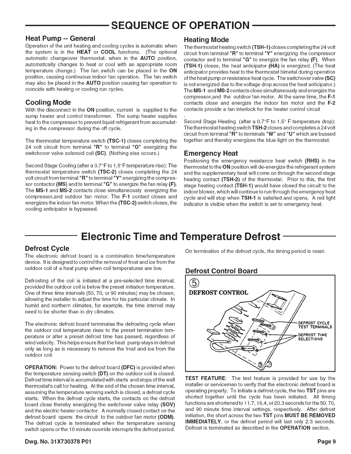
Defrost Control Board
@
DEFROST CONTROL
TEST FEATURE: The test feature is provided for use by the
installer or serviceman to verify that the electronic defrost board is
operating properly. To initiate a defrost cycle, the two TST pins are
shorted together until the cycle has been initiated. All timing
functions are shortened to 11.7, 16.4, or 20.3 seconds for the 50, 70,
and 90 minute time interval settings, respectively. After defrost
initiation, the short across the two TST pins MUST BE REMOVED
IMMEDIATELY, or the defrost period will last only 2.3 seconds.
Defrost is terminated as described in the OPERATION section.
Dwg. No. 31X730378 P01 Page 9