17
Note: Always route refrigerant hoses through the port
hole provided and have compressor access panel in
place.
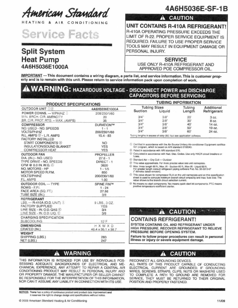
Check the suction and discharge pressures and compare
them to the normal operating pressures provided in the unit’s
Service Facts.
Note: Do not use pressures from Service Facts to
determine the unit refrigerant charge. The correct
charge is shown on the unit nameplate. To charge the
system accurately, weigh the cha
rge.
Voltage
With the compressor operating, check the line voltage at the
unit. The voltage should be within the range shown on the unit
nameplate. If low voltage is encountered, check the size and
length of the supply line from the main disconnect to the unit.
The line may be undersized for the length of the run.
Cooling Shut Down
To exit the test mode, disconnect unit power for 3-5 seconds
and reapply. When running the unit using the zone sensor as
the control, position the selector switch at “Off”. There may
be a delay of up to 3 minutes before compressors shut down
and an additional 1 minute before the fan shuts down in this
setting.
Do not de-energize main power disconnect except when unit
is to be serviced. Power is required to keep air conditioning
compressor crankcase warm and boil off refrigerant in the oil.
Exception - Circuit #1 on 181 and 211 units and both circuits
on the 200, 240 thru 301 units are not equipped with crank-
case heaters.
Compressor Overload Protection
Important: Circuit #1 on the 181 and 211 units and
both circuits of the 200,240,241,300 and 301 are
equipped with external compressor overload
protection. When an overload is detected the
breaker(s) will trip and the UCP will lock out the
compressor(s). When this happens, the breaker(s)
and the UCP must be reset.
To reset the breaker(s), open and lock unit disconnect.
Remove the compressor access panel. It is not necessary to
remove the control box cover. To reset the breaker, move the
toggle handle up. Replace the compressor access panel.
Close unit disconnect switch to resume normal operations, do-
ing this will reset the UCP.
(EDC) Evaporator Defrost Control
During low ambient operation (below 55 degree F for single
condenser fan units, and below 40 degree F for dual con-
denser fan units) compressor run time is accumulated by the
UCP. When compressor run time reaches approximately 10
minutes, an evaporator defrost cycle is initiated. The defrost
cycle lasts approximately 3 minutes.
During a defrost cycle, The compressor(s) are turned off and
the indoor motor continues to run.After completing the defrost
cycle the unit returns to normal operation, and the compressor
Starting The Unit In The Cooling Mode
IIMPORTANT NOTE:
Before starting the system in the
cooling cycle, turn the zone sensor switch to “off”
and close the unit disconnect switch. This procedure
energizes the compressor crankcase heaters,
vaporizing any liquid refrigerant in the crankcase.
This is a precaution against foaming at start-up,
which could damage the compressor bearings. Allow
the heater to operate for a minimum of eight hours.
Exception - Circuit #1 on 181 and 211 units and both circuits
on the 200, 240 thru 301 units are not equipped with crank-
case heaters.
Electrical Phasing (Scroll Compressors) If compressor
electrical phasing is incorrect , compressor and indoor fan
will operate in reverse, several symptoms will be apparent.
Compressors will draw low current.
Suction and discharge pressure will change very little.
A slight rattling or rumbling sound may be apparent.
Unit will not cool
Indoor fan (evaporator) will run backwards
If allowed to run backward for an extended period (5 minutes),
the motor windings will overheat and cause the compressor to
cycle on its thermal protector and the oil will be pumped out of
the compressor.
To correct the rotation, open unit disconnect and interchange
any two of the line wires at the high voltage terminal block, in
the control box.
Open and lock unit
disconnect switch before continuing installation.
Failure to do so could result in severe personal injury
or death due to electrical shock or contact with
moving parts.
Verify that the unit airflow rate is adjusted according to infor-
mation provided in “Determining Evaporator Fan Adjustment”
section of this manual.
Note: See “Sequence of operation” in the unit
Service Facts for a complete description of cooling
operating sequence.
To start the unit in the cooling mode, Close unit disconnect
switch and set the zone sensor system switch to COOL and
move the cooling setpoint approximately 10 degrees below
room temperature. There will be a delay of up to 5 minutes be-
fore the unit will start automatically.
To bypass time delays, and verify the operation of this unit
from the roof, use the “Test mode procedure” on page 3 and 4
of this manual.
Operating Pressures
After the unit has operated in the cooling mode for a short pe-
riod of time, install pressure gauges on the gauge ports of the
discharge and suction line valves.