American Time Wired Tone Generator User manual

Installation and Operation Manual
Part # H004464
Rev. 1
June 2010
Wired Tone Generator

© American Time
2
Safety Precautions
To prevent electrical shock, do not apply electrical power to the tone generator, signal relays or any other
equipment before completing all wiring connections.
When using additional equipment such as an AllSync Master or SiteSync IQ System Controller, refer to the
appropriate manual and instruction documentation before attempting setup.
For Masters/Signal Programmers and System Controllers
To protect against shorts between power and signal circuits, all wires connected to the power and signal
circuit terminals must be insulated to 300vac.
Relay contact voltage must not exceed 220vac to prevent damage.

3
© American Time
Multi Tone Generator Table of Contents
Specications ................................................................................................................................... 4
Physical Specications.................................................................................................................. 4
Output Signal Specications.......................................................................................................... 5
Operation .......................................................................................................................................... 6
Use with SiteSync IQ Wired System Controller ............................................................................... 7
Use with AllSync Wired Master...................................................................................................... 8
Use with YMP/YBP Clock/Signal Programmer ................................................................................ 9
Contact Information and Customer Support ................................................................................. 10
American Time
140 3rd Street South
PO Box 707
Dassel, MN 55325-0707
Phone: 800-328-8996
Fax: 800-789-1882
atsclock.com

© American Time
4
Multi Tone Generator
Contact
Information
Operation Specications
Specications
Physical Specications
• Dimensions: ............. 4.6"h x 5.6"w x 2.8"d
• Weight: ..................... 10.1 oz.
• Voltage Input: ............ 120vac power module (included)
• Enclosure................... Light gray plastic
GAIN
T1
T2
T3
T4
8 OHM
P/A
AMP
TONE SELECT
PWR
MOD
COM
COM
SPKR
SPKR
AUDIO IN
AUDIO OUT
(+)
(-)
12VDC
Multi-Tone Generator
(500 mA max)
1-800-328-8996 www.atsclock.com
5.60"
5.23"
4.60"
4.60"3.50"
2.30"
2.80"
The tone generator is compact, easy to use, light weight and versatile. This manual covers the basic
use and operation of the device. The tone generator comes in a durable gray plastic enclosure which is
designed for easy mounting.
Order Information
Part # H004291A

5
© American Time
Multi Tone Generator
Contact
Information
OperationSpecications
Specications
Output Signal Specications
Rated Output:................ Adjustable from 0-1.15 volt P-P
Load Impedance: .......... 600 ohms or higher
Power Requirements: ... 12-15vdc, 1 amp maximum; plug-in power module included
Controls:........................ Gain control - Screwdriver adjustment on the front panel
Inputs: ........................... T1-T4 four dry contact inputs for tone selection. The Audio In input
....................................... allows normal background audio to play. Pre-empted by tone selection inputs
....................................... T1-T4.
• Steady tones and Whoop last for the duration of the
contact input.
• Pulsed tones are 0.4 seconds ON and 0.4 seconds OFF
with a one second break before repeating.
• A two pulse tone repeats every 2.5 seconds for the
duration of contact input.
• A three pulse tone repeats every 3.25 seconds for the
duration of the contact input.
• The Chime sounds once when the contact is closed and
again when the contact is opened.

© American Time
6
Multi Tone Generator
Contact
Information
Operation Specications
Operation
The audio input and output can be added to any amplier, intercom or paging system. The unit can
send one of the preselected tones or background music supplied by another music source.
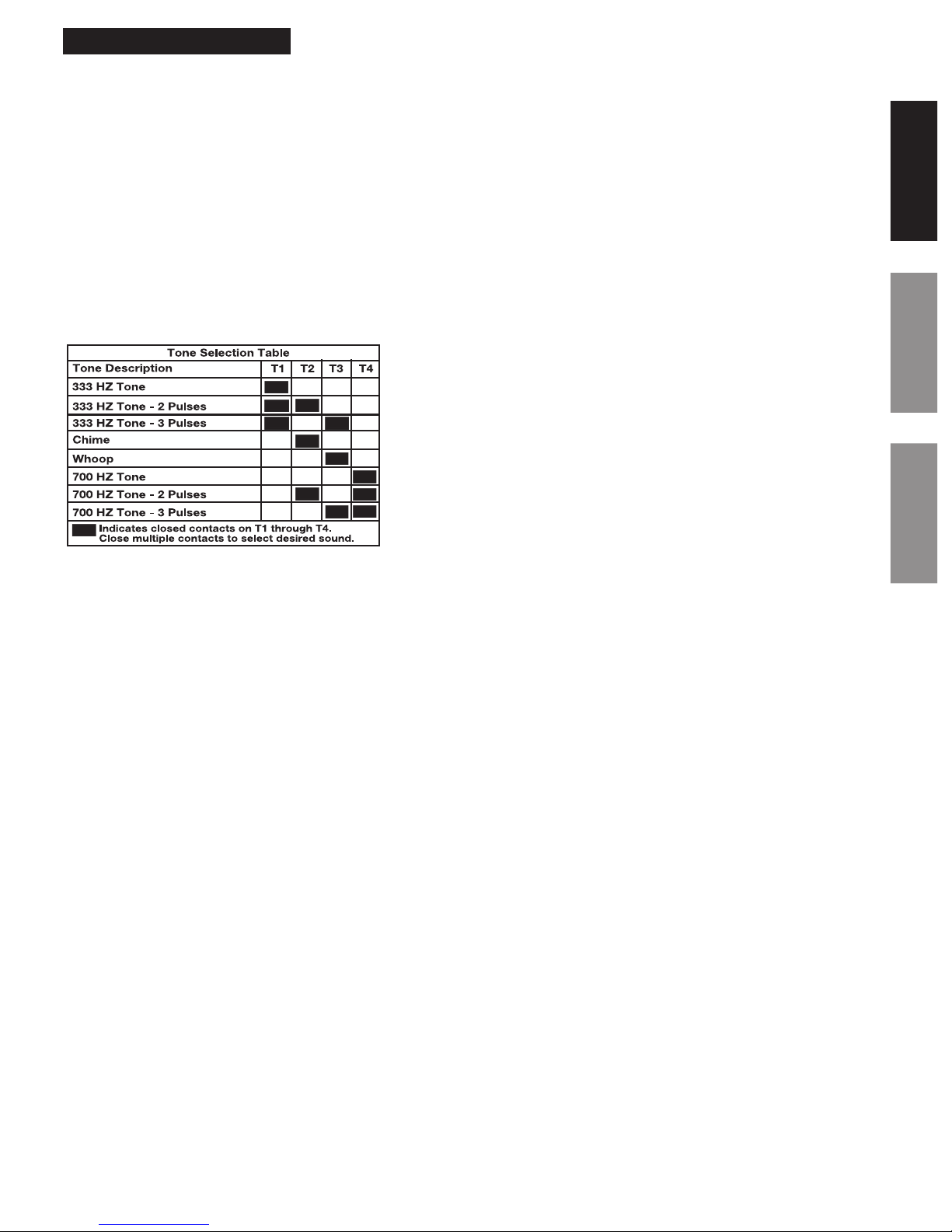
The tone generator has eight distinct tones which can be triggered by closing a wired connection
between the C (Tone Selection Common) and the proper T1, T2, T3 and T4 combination located on
the terminal block. The Tone Selection Table (see below) lists which T1 through T4 combinations are
needed for each desired tone.
The Power, Audio Input and Audio Outputs are also connected and labeled on the terminal block.
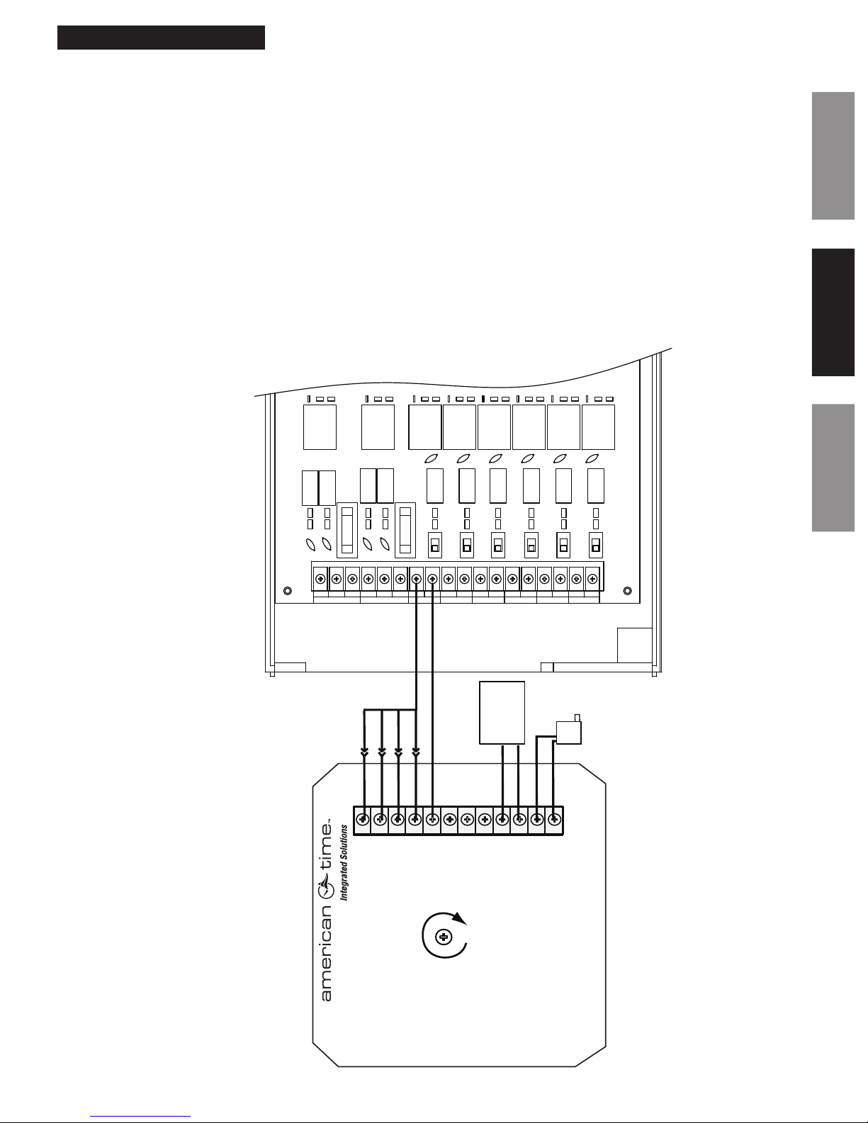
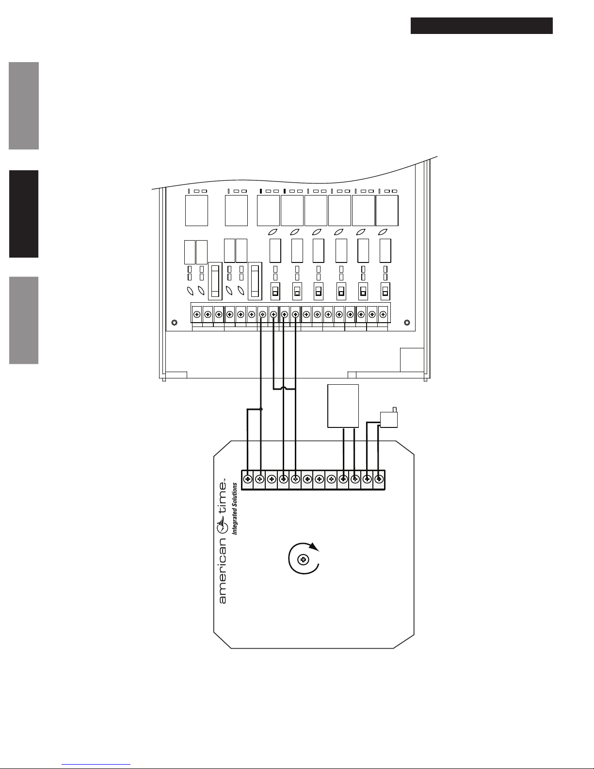
Apply a contact closure from T1, T2, T3 or T4 to C from
a time switch, master clock or push button control.
Apply jumpers to the T1, T2, T3 or T4 terminals as
required for additional tones. See the Tone Selection
Table below.
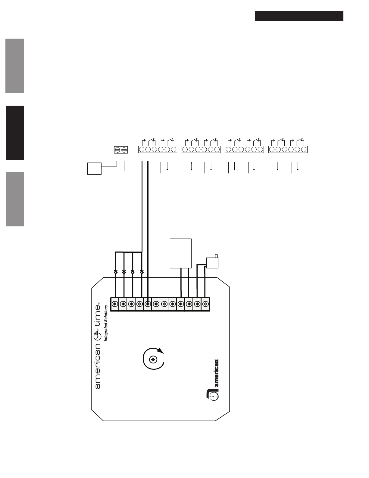
Speaker output (optional)
Connect the background audio from existing system to
the Audio In. Connect the Audio Out to the input of the
existing system.
GAIN
T1
T2
T3
T4
8 OHM
P/A
AMP
TONE SELECT
PWR
MOD
COM
COM
SPKR
SPKR
AUDIO IN
AUDIO OUT
(+)
(-)
12VDC
Multi-Tone Generator
(500 mA max)
1-800-328-8996 www.atsclock.com

7
© American Time
Multi Tone Generator
Contact
Information
OperationSpecications
Operation
Use with SiteSync IQ®System Controllers
The tone generator can also be used in conjunction with the SiteSync IQ System Controller to schedule
the triggering of tones. This can be done by hardwiring the tone generator to the SiteSync IQ System
Controller or wirelessly through the SiteSync IQ transmitter.
The unit can be triggered by wiring the desired T1-T4 combinations to the NO terminal of one of the six
bell circuits located on the back of the SiteSync IQ system controller. The COM terminal of the system
controller bell circuit should then be connected to the C terminal (Tone Selection Common). The user
can now set up circuit events on the SiteSync IQ system controller which control when and how long
the desired tone is triggered off and on.
nNote: See the SiteSync IQ Wireless Installation Manual before installation. Also, verify that the
system controller you have has the bell circuit option.
REAR OF SYSTEM CONTROLLER
COMNO NC NCCOMNO NO COM NO COM COMNO NO COM NO COM NO COM
CLOCK 1 CLOCK 2 BELL 1 BELL 2 BELL 3 BELL 4 BELL 5 BELL 6
GAIN
T1
T2
T3
T4
PA/AMP
IN
COM
Red (+)
Blk (-)
COM
COM
SPKR
SPKR
AUDIO IN
AUDIO OUT
(+)
(-)
12VDC
Multi-Tone Generator
(500 mA max)
1-800-328-8996 www.atsclock.com
Wiring Diagram

© American Time
8
Multi Tone Generator
Contact
Information
Operation Specications
Operation
REAR OF SYSTEM CONTROLLER
COMNO NC NCCOMNO NO COM NO COM COMNO NO COM NO COM NO COM
CLOCK 1 CLOCK 2 BELL 1 BELL 2 BELL 3 BELL 4 BELL 5 BELL 6
GAIN
T1
T2
T3
T4
PA/AMP
IN
COM
Red (+)
Blk (-)
COM
COM
SPKR
SPKR
AUDIO IN
AUDIO OUT
(+)
(-)
12VDC
Multi-Tone Generator
(500 mA max)
1-800-328-8996 www.atsclock.com
Wiring Example – Operating multiple tones with multiple circuits
Bell Circuit 1
activating the 333Hz
2 pulse tone.
Bell Circuit 2
activating the 700Hz
steady tone.

9
© American Time
Multi Tone Generator
Contact
Information
OperationSpecications
Operation
Use with AllSync®Masters
The tone generator can be easily triggered by an AllSync Master. The gure below shows one way of
wiring the tone generator to the master.
nNote: See the AllSync Installation Manual before installation. Also, verify that the master you have
has the bell circuit option.
Bottom of the AllSync Master
NO
CLOCK 1 CLOCK 2 BELL 1 BELL 2 BELL 3 BELL 4 BELL 5 BELL 6
CNC NO CNC NO CNO C NO C NO CNO C NO C
GAIN
T1
T2
T3
T4
PA/AMP
IN
COM
Red (+)
Blk (-)
COM
COM
SPKR
SPKR
AUDIO IN
AUDIO OUT
(+)
(-)
12VDC
Multi-Tone Generator
(500 mA max)
1-800-328-8996 www.atsclock.com

© American Time
10
Multi Tone Generator
Contact
Information
Operation Specications
Operation
Use with YMP Plus/YBP Plus Clock/Signal Programmers
The tone generator can easily be triggered by the YMP Plus or YBP Plus Clock/Signal Programmers.
The gure below shows one way of wiring the tone generator to the clock/signal programmer. Setting
the schedule to trigger the circuits is described in the YMP Plus and YBP Plus Installation Manuals.
nNote: See the YMP Plus or YBP Plus Installation Manual before installation. Also, verify that the
master you have has the circuit option.
CIRCUIT
1CIRCUIT
2CIRCUIT
3CIRCUIT
4CIRCUIT
5CIRCUIT
6CIRCUIT
7CIRCUIT
8
NO
1 C
1NC
1 NO
2 C
2NC
2 NO
3 C
3NC
3 NO
4 C
4NC
4 NO
5 C
5NC
5 NO
6 C
6NC
6 NO
7 C
7NC
7 NO
8 C
8NC
8
GAIN
T1
T2
T3
T4
PA/AMP
IN
COM
Red (+)
Blk (-)
COM
COM
SPKR
SPKR
AUDIO IN
AUDIO OUT
(+)
(-)
12VDC
Multi-Tone Generator
(500 mA max)
1-800-328-8996 www.atsclock.com
120vac
Input
Fused
120vac
Source
Black
White
AC
IN AC
RTN

11
© American Time
Multi Tone Generator Contact Information
Contact
Information
OperationSpecications
For additional support on product setup, on the tone generator or on any of the American Time
products, please call or visit our web site.
American Time
140 3rd St. So.
PO Box 707
Dassel, MN 55325-0707
Toll Free Phone: 800-328-8996
Toll Free Fax: 800-789-1882
atsclock.com
This manual suits for next models
1
Table of contents
Other American Time Recording Equipment manuals