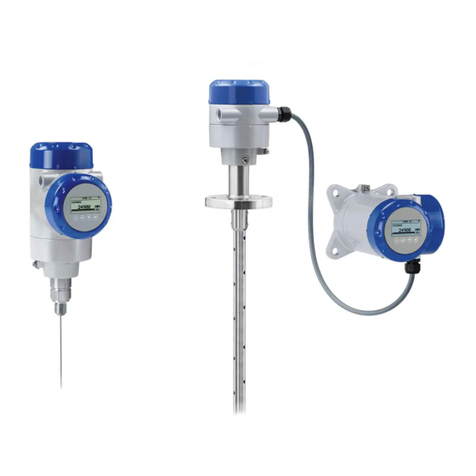
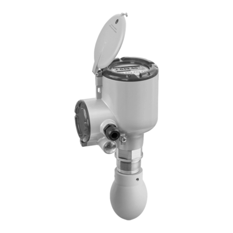
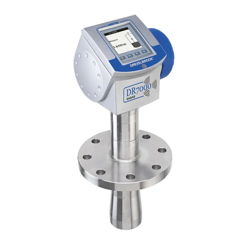
Ametek Drexelbrook VeriGAP 504-1000 Series Installation and operating instructions

Installation & Maintenance Instructions
504-1000 Series VeriGAP™
Ultrasonic Level Switch using:
404-1000 and 404-1060 Series Electronics
Reading Office
Cutbush Park, Danehill, Lower Earley,
Reading, Berkshire. RG6 4UT. UK.
Tel: +44 (0)118 9311188
Email: [email protected]
Aberdeen Office
Unit 6 Airside Business Park, Kirkhill Industrial Estate,
Dyce, Aberdeen. AB21 0GT. UK.
Tel: +44 (0)1224 725999
Email: [email protected]
Internet: www.able.co.uk
e-procurement: www.247able.com
Registered in England No: 01851002
VAT No: GB 417 2481 61

AMETEK Drexelbrook makes no warranty of any kind with regard to the material contained in this manual,
including, but not limited to, implied warranties or fitness for a particular purpose. Drexelbrook shall not
be liable for errors contained herein or for incidental or consequential damages in connection with the
performance or use of material.
© Copyright AMETEK Drexelbrook

EDO# 09-07-102
504-1000-000-LM
Issue #7
504-1000 Series VeriGAP™
Ultrasonic Level Switch
using:
404-1000 and 404-1060
Series Electronics


Contents

Table of Contents
Section 1: Introduction..................................................................................................................... 1
1.1 General Description ............................................................................................................. 1
1.2 VerifyTM Circuit ................................................................................................................... 1
1.3 Model Numbering ................................................................................................................ 2
Section 2: Installation....................................................................................................................... 3
2.1 Unpacking............................................................................................................................ 3
2.2 Mounting The Instrument..................................................................................................... 3
2.3 Wiring The Instrument.......................................................................................................... 6
2.4 Relay Wiring......................................................................................................................... 7
Section 3: Operation....................................................................................................................... 13
3.1 Failsafe Selector ................................................................................................................ 13
3.2 Manual Verify™ Test .......................................................................................................... 14
3.3 Auto Verify™ ...................................................................................................................... 14
Section 4: Troubleshooting............................................................................................................ 15
Section 5: Factory Assistance and Field Service ........................................................................ 17
5.1 Telephone Assistance........................................................................................................ 17
5.2 Field Service...................................................................................................................... 17
5.3 Equipment Return / Warranty ............................................................................................ 18
Section 6: Specifications ............................................................................................................... 19
6.1 Electronics ......................................................................................................................... 19
6.2 Sensing Element................................................................................................................ 20
Section 7: Approval Control Drawings ......................................................................................... 21
7.1 FM and CSA Approval Control Drawings........................................................................... 21

Introduction

Introduction
1
Section 1: Introduction
1.1 General Description
The 504-1000 Series ultrasonic VeriGAP™ switch is an integral assembly
which senses liquid presence by ultrasonic techniques and energizes a relay
which can be utilized to indicate and/or control the liquid at a predetermined
level.
A high frequency acoustic signal is transmitted through the sensor gap when
liquid is present. When liquid is not present, no signal transmission occurs.
See Figure 1-1. When a signal is received, an electronic circuit produces a
relay output. The ultrasonic sensor does not contain moving components.
It is not affected by electrical or physical parameters of the process material
and will operate over a wide temperature range. These characteristics make
the 504-1000 a very reliable and economical solution to industrial liquid
level control operations.
2
1.1 General
Description
(continued)
1.1.1 VerifyTM
Circuit
504-1200 Series Ultrasonic VeriGAPTM Introduction
A high frequency acoustic signal is transmitted through the
sensor gap when liquid is present. When liquid is not present,
no signal transmission occurs. See Figure 1-3. When a signal
is received, an electronic circuit produces a relay output.
Gap in Air Gap Submerged
Figure 1-3
Gap Switch Operation
The ultrasonic sensor does not contain moving components. It
is not affected by electrical or physical parameters of the
process material and will operate over a wide temperature
range. These characteristics make the 504-1200 a very reli-
able and economical solution to industrial liquid level control
operations.The ultrasonic sensor does not contain moving com-
ponents and is not affected by electrical or physical param-
eters of the liquid. These characteristics make the VeriGAP a
very reliable and economical solution to industrial liquid level
control operations.
Inherent benefits of the VeriGAP include high reliability and
minimum maintenance, as they are not affected by variations
in liquid viscosity, density, pressure, temperature, or electrical
properties. For applications where the sensor will be coated or
the liquid is aerated, consult the factory at 1-800-527-6297.
As an option, the ultrasonic two-wire VerifyTM circuit is used in
conjunction with the VeriGAP for pushbutton verification
that the entire control system is functioning properly. This
option is used with High Level Fail-safe devices only. It simu-
lates a high level at the sensing element to meet spill preven-
tion regulations and recommended practices. This test may
also be used for ISO 9000 validation of your high level
alarms and spill prevention systems.
An optional Drexelbrook Point Level Receiver provides power
to the VeriGAP and monitors its current draw. Relays are
activated on change of level states.
RCV TX RCV TX
Figure 1-1
Gap Switch Operation
1.2 VerifyTM Circuit
As an option, the ultrasonic two-wire Verify™ circuit is used in conjunction
with the VeriGAP for pushbutton verication that the entire control system
is functioning properly. This option is used with High Level Fail-safe devices
only. It simulates a high level at the sensing element to meet spill prevention
regulationsandrecommendedpractices.Thistestmay alsobeusedforISO9000
validation of your high level alarms and spill prevention systems.

504-1000 Series Ultrasonic VeriGAP™
2
1.3 Model Numbering
Technology
504 VeriGAp Switch
5 0 4 1 0 0
Power / Output
0120 VAC, DPDT Relay
124 VDC, DPDT Relay
224 VDC. Loop Powered (Separate Instruction Manual)
3240 VAC, DPDT Relay
6Dual Gap, 2 DPDT Relays
Configuration
0Integral Electronics
7Remote Electronics
Sensing Element
01 316SS
03 Alloy 20
05 Hastelloy “C”
08 3A Approved Sanitary 316SS
Electronics
404 VeriGAp Switch
4 0 4 1 00
Number of Points
0Single Point
6Dual Point
Test Circuit
0No Testing
VVerify
AAuto Verify
Housing Option
1No Housing, chassis only
25”, Y-Hub, Remote, Explosion-Proof
35”, Y-Hub, Remote, Explosion-Proof, with Drexelcote™
4Remote, NEMA 4X, Explosion-Proof
6Remote, NEMA 4X, Explosion-Proof with Drexelcote™
8Integral, NEMA 4X, Explosion-Proof with Drexelcote™
9Integral, NEMA 4X, Explosion-Proof
F5”, Y-Hub, Integral, Explosion-Proof
C5”, Y-Hub, Integral, Explosion-Proof, with Drexelcote™
Power / Output
0120 VAC, DPDT Relay
124 VDC, DPDT Relay
224 VDC. Loop Powered (Separate Instruction Manual)
3240 VAC, DPDT Relay

Installation
3
Section 2: Installation
2.1 Unpacking
Carefully remove the contents of the shipping carton and check each item
against the packing list before destroying any packing material. If there
is any shortage or damage, report it immediately to the factory (1-800-527-
6297).
2.2 Mounting The Instrument
The 504-1000 electronic unit was designed for eld mounting, but it should be
mounted in a location as free as possible from vibration, corrosive atmospheres,
and any possibility of mechanical damage. For convenience at start-up, place
the instrument in a reasonably accessible location. Ambient temperatures
should be between -40°F and 160°F (-40°C to 70°C).
VeriGAP switches can be mounted in any orientation vertically. If the unit
is mounted horizontally, rotate the sensor so that the electrical hub is down
and the sensor slot is vertical. This allows any product buildup on the sensor
to fall free. Note orientation of wrench ats relative to the gap.
Figure 2-1
Mounting Orientation
4
Carefully remove the contents of the shipping carton and
check each item against the packing list before destroying any
packing material. If there is any shortage or damage, report
it immediately to the factory (1-800-527-6297).
The 504-1200 electronic unit was designed for field mounting,
but it should be mounted in a location as free as possible from
vibration, corrosive atmospheres, and any possibility of me-
chanical damage. For convenience at start-up, place the
instrument in a reasonably accessible location. Ambient
temperatures should be between -40°F and 160°F (-40°C to
70°C).
The 504-1200 VeriGAP™ switches can be mounted in any
orientation vertically.
Figure 2-1
Mounting Orientation
SECTION 2
INSTALLATION
2.1 Unpacking
2.2 Mounting the
Instrument
504-1200 Series Ultrasonic VeriGAPTM Installation
NOTE
If the unit is mounted
horizontally, rotate the
sensor so that the electri-
cal hub is down and the
sensor slot is vertical.
This allows any product
buildup on the sensor to
fall free. Note orientation
of wrench flats relative to
the gap.
`
GAP
MOUNTED
VERTICALLY
MATERIAL
DRAINS
AWAY
WRENCH FLATS
HORIZONTAL
GAP PLUGS
WITH MATERIAL
WRONG
CORRECT
WRONG
See NOTE

504-1000 Series Ultrasonic VeriGAP™
4
4
Figure 2-2
Mounting Dimensions
Single Gap, Integral Unit
All dimensions in inches (mm)
504-1000 Series Ultrasonic VeriGAPTM Installation
Figure 2-2
Mounting Dimensions, Integral Unit
5
Figure 2-3
Mounting Dimensions
Single Gap, Remote Unit
504-1000 Series Ultrasonic VeriGAPTM Installation
All dimensions in inches (mm)
Figure 2-3
Mounting Dimensions, Remote Mounting

Installation
5
Figure 2-4
Mounting Dimensions, Verify™ Housing
Figure 2-5
Mounting Dimensions, Dual Gap
6
Figure 2-4
Mounting Dimensions
Single Gap with Verify Housing
All dimensions in inches (mm)
504-1000 Series Ultrasonic VeriGAPTM Installation
7
Figure 2-5
Mounting Dimensions
Dual Gap
504-1000 Series Ultrasonic VeriGAPTM Installation

504-1000 Series Ultrasonic VeriGAP™
6
2.3 Wiring The Instrument
CAUTION
Ensure that all wiring, electrical ttings and conduit connections conform
to your local electrical codes for the location and environment of use. If the
504-1000 Gap Switch is located in a hazardous environment, do not open
the enclosure cover or make/break any electrical connections without rst
disconnecting electrical power at the source.
Use the following procedure to wire the 504-1000 Switch:
1. Ensure that the power is off.
2. Remove the cover.
3. Make all electrical connections to the Switch per the wiring diagram
shown in Figure 2-7 through Figure 2-9. Use 14-gauge or smaller wiring.
All connections are made on the terminal strip.
4. The PC board mounting screws can be removed to allow movement of the
PC board during wiring.
5. After connections are secured and dressed, re-insert the PC board and
close the enclosure cover.
7. Review Checklist:
• Wiring correct?
• Proper input voltage used?
• Proper relay state at the receiver
(relays will be in the alarm condition)?
8. Turn power on.
• Make sure that the 115 Vac supply is clean and free of noise.
• Do not supply power to the VeriGAP that originates at a variable frequency
drive motor supply.
• Do not run relay wires or supply wires in same conduit as variable
frequency drive wiring.

Installation
7
Figure 2-6
Relay Wiring
9
Figure 2-6
Relay Wiring
Figure 2-6 shows the relay wiring for the 504-1000.2.3.1 Relay
Wiring
504-1000 Series Ultrasonic VeriGAPTM Installation
Material
LOW LEVEL
RELAY CONTACT CHART
(Power applied to instrument)
Material
HIGH LEVEL
LOW LEVEL
FAIL SAFE
HIGH LEVEL
FAIL SAFE
NC1
C 1
NO1
NC2
C 2
NO2
NC1
C 1
NO1
NC2
C 2
NO2
NC1
C 1
NO1
NC2
C 2
NO2
NC1
C 1
NO1
NC2
C 2
NO2
2.4 Relay Wiring

504-1000 Series Ultrasonic VeriGAP™
8
Figure 2-7
Wiring Diagram, 120 / 240 VAC, Integral Gap Switch
10
Figure 2-7
Wiring the 120/240 Vac
Integral VeriGAP Switch
504-1000 Series Ultrasonic VeriGAPTM Installation
11
Figure 2-8
Wiring the 120/240 Vac
Remote VeriGAP Switch
504-1000 Series Ultrasonic VeriGAPTM Installation
Figure 2-8
Wiring Diagram, 120 / 240 VAC, Remote Gap Switch

Installation
9
12
Figure 2-9
Wiring the 24 Vdc
Integral VeriGAP Switch
504-1000 Series Ultrasonic VeriGAPTM Installation
13
Figure 2-10
Wiring the 24 Vdc
Remote VeriGAP Switch
504-1000 Series Ultrasonic VeriGAPTM Installation
Figure 2-9
Wiring Diagram, 24 VDC, Integral Gap Switch
Figure 2-10
Wiring Diagram, 24 VDC, Remote Gap Switch

504-1000 Series Ultrasonic VeriGAP™
10
14
Figure 2-11 (View 1)
Wiring the 120/240 Vac
VeriGAP Switch with Verify
504-1000 Series Ultrasonic VeriGAPTM Installation
15
Figure 2-11(View 2)
Wiring the 120/240 Vac
VeriGAP Switch with Verify
504-1000 Series Ultrasonic VeriGAPTM Installation
Figure 2-11 View 2
Wiring Diagram, 120 / 240 VAC, Gap Switch with Verify
Figure 2-11 View 1
Wiring Diagram, 120 / 240 VAC, Gap Switch with Verify
15
Figure 2-11(View 2)
Wiring the 120/240 Vac
VeriGAP Switch with Verify
504-1000 Series Ultrasonic VeriGAPTM Installation

Installation
11
Figure 2-12
Wiring Diagram, 120 / 240 VAC, Integral, Dual, Gap Switch
16
Figure 2-12
Wiring the 120/240 Vac
Integral Dual Gap Switch
504-1000 Series Ultrasonic VeriGAPTM Installation
17
Figure 2-13
Wiring the 120/240 Vac
Remote Dual Gap Switch
504-1000 Series Ultrasonic VeriGAPTM Installation
Figure 2-13
Wiring Diagram, 120 / 240 VAC, Remote, Dual, Gap Switch

504-1000 Series Ultrasonic VeriGAP™
12
18
Figure 2-14
Wiring the 24 Vdc
Integral Dual Gap Switch
504-1000 Series Ultrasonic VeriGAPTM Installation
19
Figure 2-15
Wiring the 24 Vdc
Remote Dual Gap Switch
504-1000 Series Ultrasonic VeriGAPTM Installation
Figure 2-14
Wiring Diagram, 24 VDC, Integral, Dual, Gap Switch
Figure 2-15
Wiring Diagram, 24 VDC, Remote, Dual, Gap Switch

Operation
13
Section 3: Operation
3.1 Failsafe Selector
The VeriGAP switch operates successfully upon applying power to the unit
No further calibration or adjustments are necessary.
There is one operating switch on the instrument for failsafe selection.
Failsafe describes the level condition that causes the output signal to change
states.
• High Level Failsafe (HLFS) means the output signal will change to the
alarm state under high level conditions (indicating high level upon loss
of power.
• Low Level Failsafe (LLFS) means the output signal will change to the
alarm state under low level conditions (indicating low level upon loss of
power.
• The instrument is supplied in the failsafe mode that is requested when
the order is placed (HLFS, if not specied).
• The failsafe is eld selectable by changing slide switch S1 on the power
side of the unit. See Figure 3-1.
12
504-1200 Series Ultrasonic VeriGAPTM Operation
The VeriGAP switch operates successfully upon applying
power to the unit . No further calibration or adjustments are
necessary.
There is one operating switch on the instrument for failsafe
selection.
Failsafe describes the level condition that causes the output
signal to change states.
• High Level Failsafe (HLFS) means the output signal will
change to the alarm state under high level conditions (indi-
cating high level upon loss of power.
• Low Level Failsafe (LLFS) means the output signal will
change to the alarm state under low level conditions (indi-
cating low level upon loss of power.
• The instrument is supplied in the failsafe mode that is
requested when the order is placed (HLFS, if not speci-
fied).
• The failsafe is field selectable by changing the link on the
top of the unit. See Figure 3-1.
Figure 3-1
Failsafe Switch Settings
SECTION 3
OPERATION
3.1 Failsafe
Selector
Figure 3-1
Failsafe Switch Settings
Table of contents
Other Ametek Drexelbrook Measuring Instrument manuals
Popular Measuring Instrument manuals by other brands

S+S Regeltechnik
S+S Regeltechnik AERASGARD FSFTM-CO2-Modbus Series Operating Instructions, Mounting & Installation

CTC Union
CTC Union SB252 Series product manual

MICRO-EPSILON
MICRO-EPSILON scanCONTROL 2910 Assembly instructions

Hanna Instruments
Hanna Instruments HI 96734C instruction manual

Halma
Halma Ocean Optics LASER-785-IP-LAB Installation and operation manual

HT
HT HT3300 user manual