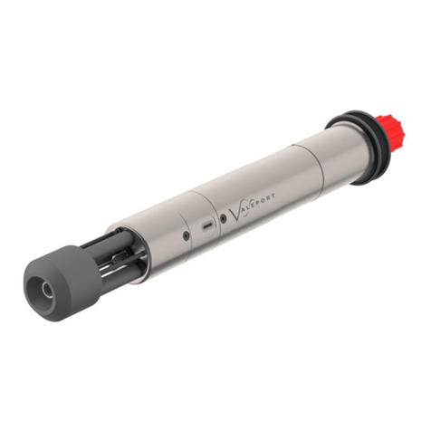
TECALEMIT TecSonic 225800200 User manual

Operating manual
Item no.: 225800200, 225800400
Translation of original
operating manual
Fig. 225800200

Important!
The operating manual is always to be read before commissioning the
equipment. No warranty claim will be granted for faults and damage to the
equipment arising from insufficient knowledge of the operating manual.
Copyright
© TECALEMIT GmbH & Co. KG - All rights reserved.
Text, graphics and layout copyright protected. Reproduction and copying, including
in part, only permitted with written permission. Technical changes reserved.

Contents
1Safety instructions .............................................................................. 4
2Technical description........................................................................... 5
2.1 Description / Intended use.............................................................. 5
2.2 Versions ...................................................................................... 5
2.3 Technical specifications .................................................................. 5
2.3.1 Wireless frequency G2 ......................................................... 5
2.3.2 Wireless frequency G4 ......................................................... 5
2.4 Battery change ............................................................................. 6
2.5 Accessories .................................................................................. 6
3Activation ............................................................................................ 7
3.1 2G/GPRS ..................................................................................... 7
3.2 4G/LTE........................................................................................ 7
4Installation.......................................................................................... 8
5Login ................................................................................................... 9
6Beep Patterns .................................................................................... 11
6.1 LED Patterns (only 4G/LTE) ...........................................................11
7Disposal............................................................................................. 12
7.1 Disposing of the device .................................................................12
7.2 Disposal of batteries .....................................................................12
8Declaration of Conformity.................................................................. 13
9Waveguide......................................................................................... 13

1Safety instructions
This device was manufactured taking into account the relevant laws and directives for
ensuring security as well as the protection of the environment and health. Despite this, its
use may result in hazards for persons and material assets. Hence, it is essential that the
instructions in this manual are complied with.
Warning notices and symbols
In this operating manual, the following symbols are used to point out especially
important information:
Specific details on the economic use of the device.
Specific details and/or instructions for damage prevention.
Details and/or instructions for preventing injury to persons or
extensive material damages.
Intended use
Use the device only when it is in perfect working condition and only for its intended
purpose while observing all safety precautions and risks. In particular, all
malfunctions that could pose a safety hazard are to be corrected immediately.
The device and its components are intended for use exclusively with the liquids
listed and only for the purpose described. Any other use or additional manner of
usage is not intended.
Organisational measures
This operating manual is to be kept within easy reach at the place of operation. The
nameplate and the warning labels on the device must be observed and kept
completely legible at all times.
Qualified personnel
The personnel for installation, commissioning, operation, and maintenance of the
device must possess the relevant and adequate qualifications for these tasks. The
operator must ensure that the contents of this manual are fully understood and
implemented by the personnel.
Maintenance and repairs
Do not make any changes, extensions and/or modifications to the device without
the manufacturer's permission. Replacement parts must conform to the technical
specifications defined by the manufacturer. For original parts, this conformity is
always guaranteed.
Hazardous substances
In exceptional cases, the components of this device may contain hazardous
substances. In accordance with the requirements of the European REACH
regulation, we provide current information on this on our homepage, in the
download section.
Observe all safety regulations for the respective product when handling oils,
greases, fuels and other chemical substances!

Techni
2Technical description
2.1 Description / Intended use
The TecSonic ultrasonic sensor which uses ultrasonic technology to measure the
liquid level of your tank and then communicates this data to a remote server.
2.2 Versions
Item no. Type
225800200 TesSonic mobile 2G/GPRS
225800400 TecSonic mobile 4G/LTE
2.3 Technical specifications
Dimensions (WxHxD) 101x150x93 mm ±1 mm
Supply voltage 4x 1,5 V battery Type C LR14 (incorporated)
Alkali-Mangan-Dioxid - ZnMnO2
Connection thread 1 ¼“, 1 ½“, and 2“ BSP
Material measured diesel, fuel oil, kerosene, water, waste oil
Temperature range Operation G2: -10° C to 50° C / G4: -20° C to 50° C
Temperature range Storage -30° C to 60° C
Protection class IP67
Ultrasound range G2: >12 cm up to <3 m / G4: >12 cm up to <4 m
Ultrasound signal deflection 30°
Ultrasound resolution ±1 cm
Measuring accuracy ±2 cm
Weight 530 g incl. battery / 290 g without battery
Housing material UV stabilized polypropylene (compatible with oil)
Altitude range <2 Km above sea level
Battery life >2 years*
Humidity 15% - 95%
SIM card M2M 1NCE (built in)
*Based on daily data transmission in standard configuration at a location with good
reception coverage.
2.3.1 Wireless frequency G2
Quad-Band GSM/GPRS
2.3.2 Wireless frequency G4
LTE FDD (Cat M1):
B1/B2/B3/B4/B5/B8/B12/B13/B18/B19/B20/B25/B26/B27/B28/B66/B85
LTE FDD (Cat NB2):
B1/B2/B3/B4/B5/B8/B12/B13/B18/B19/B20/B25/B28/B66/B71/B85
EGPRS: 850/900/1800/1900MHz

2.4 Battery change
The battery can be replaced without tools after opening the housing.
2.5 Accessories
Item no.
Name
225800020
Waveguide pipe TecSonic 2m
(Armored conduit DN32 and 2 grub screws ISO 4027 M3x4)
225800020
Waveguide pipe TecSonic 3m
(Armored conduit DN32 and 2 grub screws ISO 4027 M3x4)
225800050
Combi vent cap 2" for TecSonic mounting

3Activation
3.1 2G/GPRS
To activate the sensor, hold the supplied magnet to the
hot spot, a beep will be heard to indicate correct
placement of magnet.
Keep the magnet held to the hot spot until a second
beep is heard, remove magnet from hot spot once this
has been achieved.
A series of beeps will now be heard. This indicates the
GPRS is registering onto the GSM network.
Upon successful registration to the GSM network the sensor will attempt to
initiate a GPRS connection to the myTecalemit server. This is indicated by
higher pitched beeping.
The successful activation of the sensor is indicated by two successive short
beeps two seconds apart. This will wake the sensor from dormant mode and
activate it to make a join-request to the server.
It is recommended to log in to myTecalemit to check whether the sensor
readings are received on the server and whether the readings are OK before
leaving the installation site.
3.2 4G/LTE
To activate the sensor, hold the supplied magnet to the
hot spot which can be found directly below the LED.
As the magnet is held to the hot spot, the LED will first
flash Green then flash Red, after this the Red LED will
light continuously, remove magnet from hot spot once
this has been achieved.
A series of beeps will be heard while this Red LED remains illuminated. This
indicates the GSM/GPRS is registering onto the cellular network.
After successful registration in the cellular network, the sensor attempts to
establish a connection to the myTecalemit server.
After successful activation of the sensor, the green LED lights up and a double
beep pattern sounds. This will wake the sensor from dormant mode and
activate it to make a join-request to the server.
It is recommended to log in to myTecalemit to check whether the sensor
readings are received on the server and whether the readings are OK before
leaving the installation site.
Hot Spot
LED
Hot Spot

4Installation
The Ultrasonic GSM works in conjunction with the myTecalemit server.
The following outlines the sensor mounting options.
The sensor must sit in a vertical position on top of the tank and be fitted such
that the sensor has a clear path to the tank contents. Position it so that there
are no internal obstructions that may interfere with the ultrasonic signal.
If obstacles cannot be avoided, then a waveguide may be required. More
detailed information see chapter Waveguide on page 13.
Locate a suitably positioned threaded opening on the top of the tank to hold
the sensor.
The sensor will fit directly into threaded 1 ¼”, 1 ½” or 2” BSP (British
Standard Pipe) existing tank connections.
Ensure that the gasket is placed, and that the sensor is screwed correctly into
the tank.
INSERTING A
TUBE, OR ANY
OTHER SHARP OR
ROUGH EDGE
THE ULTRASONIC
SIGNAL ENCOUNTERS
AN OBSTACLE IN THE
TANK
TRY TO MOUNT
SENDER AS
VERTICAL AS
POSSIBLE
Sensor
Gasket

mytecalemit.com
5Login
The device is operated in combination with our myTecalemit
web software.
Open the website mytecalemit.com in any browser and log
in using your account information. If you do not yet have an
account, please register and create a new company in
myTecalemit for your company.
For a newly created company, the mytecalemit fill level
module will first need to be activated. You can start with the
14-day trial version of the level module.
For permanent activation please contact:
Ingo Fischer, Tel.: +49 (0)461-8696-23, E-Mail: ingo.fischer@tecalemit.de
Steffen Klatt, Tel.: +49 (0)461-8696-24, E-Mail: steffen[email protected]
Once your company has been activated, you can add a new device.
Once the TecSonic is activated, please refer to chapter see chapter 3 on page 7, you
can add a new device in the menu Master data –Level sensors.
In this menu, enter a description and select the type "TecSonic mobile". In the next
step, enter the 15-digit serial number (under the barcode on the device).
You can now save the information or perform the configuration for the tank right
away before saving.

The device is now ready for use.

6Beep Patterns
Beep Pattern
Definition
Low beep once per second
Network Registration
High beep once per second
TCP connecting
Low beep once every 4 seconds
Network / TCP Listen
Low beep once every 2 seconds
Re-establish Network / TCP
High / Low combination beep
Incoming Data
Low / High combination beep
Outgoing Data
Low double-beep every 4 seconds
Network Listen (Data Received & Unit
Active)
Low double-beep every 2 seconds
Re-establish Network
High double-beep every 4 seconds
TCP Listen (Data Received & Unit Active)
High double-beep every 2 seconds
Re-establish TCP
6.1 LED Patterns (only 4G/LTE)
LED Pattern
Function
Green/ Red / Off
LED test: When a magnet is held against the hot
spot the LED will briefly indicate Green followed
briefly by Red and then off.
Red LED - On continuous
Modem Busy: Registering on Network and
sending data.
Green LED - On continuous
Activated: Server has responded and Activated
the unit.

7Disposal
7.1 Disposing of the device
Upon being decommissioned, the device is to be completely emptied and the fluid(s)
disposed of properly. Upon being taken out of service permanently, the device is to
be dismantled by specialist personnel and disposed of properly:
-Dispose of used metal parts at a recycling facility for metal.
-Bring plastic parts to a recycling center.
-Bring electrical scrap to a recycling center.
-Batteries and lamps which are not permanently sealed, glued shut,
or installed must first be removed and disposed of separately.
The end user is responsible for deleting personal data stored on the old device.
Further information on the disposal of electrical appliances can be found on our
homepage in the download section.
Observe all legal regulations concerning water protection.
7.2 Disposal of batteries
Batteries must not be disposed of with the domestic waste. Batteries can be returned
free of charge via a suitable collecting point or to the dispatch stores. Consumers are
legally obliged to return used batteries.
Batteries that contain harmful substances are marked with a crossed out dustbin (see
above) and the chemical symbol (Cd, Hg or Pb) of the heavy metal that is decisive
for the classification as containing harmful substances:
1. “Cd” stands for cadmium.
2. “Pb” stands for lead.
3. “Hg” stands for mercury.

Konformitätserkl ärung
8Declaration of Conformity
We herewith declare that the construction type
Type:
TecSonic
Designation:
Ultrasonic sensor
Item number:
225800100, 225800200, 225800400
in the form as delivered by us complies with the following applicable regulations:
–EMC directive 2014/30/EU
–RoHS-Directive 2011/65/EU
–Radio Equipment Directive 2014/53/EU
9Waveguide
The default sensor configuration is non-waveguide mode and the
measurements will be inaccurate unless a waveguide configuration mode
is used.
Source a suitable pipe to act as the waveguide. This pipe should conform the
dimensions in the figure below in order to fit the sensor. The recommended pipe
material is PVC (domestic waste pipe is often used). Other materials are possible
but should be checked for chemical resistance to fuel oil.
Cross-section of waveguide pipe assembly:
The pipe should be cleanly cut to length. The length required
should be measured from the top of the tank (where the sensor
is to be mounted) to that of the fuel outlet point (as shown).
Note: The bottom of the pipe should be a minimum of 5cm from the base (floor) of
the tank to prevent it from touching in the case of tank dimensional changes due to
temperature etc.
Maximum outer diameter of pipe 36 mm
Minimum outer diameter of pipe 34 mm
Nominal inner pipe diameter 32 mm/1,25 inch
(Minimum inner pipe diameter 31 mm)

The waveguide pipe should be securely attached via the two grub screws and hand
tightened with an M1.5 Allen key (Note: over-tightening the grub screws can
damage the plastic). Care should be taken to keep the sensor and pipe vertically
aligned and supported, while fitting during the installation.
Depending on the weight, length and surface finish of the pipe, it may be
necessary to glue it into position. In this case a hole should be drilled
near the top of the waveguide pipe, just below the adapter, to ensure that
any trapped air can exit.
Insert the correctly sized rubber seal ring, as required for the tank opening
(supplied), and position it on the face of the adapter that is screwed onto the top of
the tank.
Insert the whole assembly carefully into the tank, taking care not to loosen the
pipe, and fit into position. Hand tighten the assembly until the rubber seal locks
into position.
Air escape vent hole (2 mm diameter)
Grub Screws


TECALEMIT GmbH & Co. KG
Munketoft 42
24937 Flensburg
Germany
T +49 461-8696-0
F +49 461-8696-66
www.tecalemit.de
This manual suits for next models
1
Table of contents
Other TECALEMIT Measuring Instrument manuals
Popular Measuring Instrument manuals by other brands
Hanna Instruments
Hanna Instruments HI 84102 instruction manual

Zehntner
Zehntner ZVR 6000 instruction manual
LAPP
LAPP ETHERLINE GUARD PM03T quick start guide
National Instruments
National Instruments NI PXI-5621 specification
GREISINGER
GREISINGER G 1400 Series Quick reference guide
IGM
IGM MULTIGASSENS-M2 user manual

