Swift 25.0-9800 Rev A Page 5
8.5 Date and Time ............................................................................................... 37
8.5.1 Set Clock .....................................................................................................................37
8.5.2 Set From ......................................................................................................................38
8.6 Zero Flow ......................................................................................................39
8.7 History ..........................................................................................................39
9. SWIFT BLUETOOTH APPLICATION ................................................... 40
10. FLOW AUDIT SHEET ......................................................................... 40
Table of Figures
Figure 1-1 Swift 25.0 Flow Meter ..........................................................................................................8
Figure 2-1 Standard Components for the Swift 25.0...........................................................................12
Figure 3-1 Swift 25.0 Front View.........................................................................................................13
Figure 3-2 Swift 25.0 User Interface ...................................................................................................15
Figure 3-3 Inlet Cap Screen................................................................................................................17
Figure 3-4 Swift 25.0 Bottom View......................................................................................................18
Figure 4-1 Flow measurements on UUTs with standard 1.25” O.D. inlet ............................................21
Figure 4-2 Bluetooth Antenna .............................................................................................................22
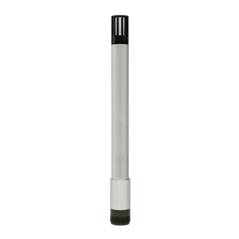
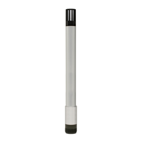
Figure 4-3 Temperature Probe............................................................................................................22
Figure 4-4 Connection to a SASS with Tubing Adaptors ....................................................................23
Figure 5-1 Inlet Assembly ...................................................................................................................24
Figure 5-2 Inlet Assembly ...................................................................................................................25
Figure 5-3 Back Panel Removal .........................................................................................................27
Figure 5-4 Battery Removal ................................................................................................................28
Figure 5-5 Battery Tray Removal ........................................................................................................28
Figure 5-6 Coin Cell Battery................................................................................................................29
Figure 5-7 Reassembly.......................................................................................................................29
Figure 7-1 File Tab..............................................................................................................................31
Figure 7-2 About Screen.....................................................................................................................31
Figure 7-3 Start Screen.......................................................................................................................32
Figure 8-1 Main Screen ......................................................................................................................33
Figure 8-2 Device and Settings...........................................................................................................34
Figure 8-3 Get Button .........................................................................................................................34
Figure 8-4 Get and Set Buttons ..........................................................................................................34
Figure 8-5 Temperature Units.............................................................................................................34
Figure 8-6 Pressure Units ...................................................................................................................35
Figure 8-7 Flow Units..........................................................................................................................35
Figure 8-8 Advanced...........................................................................................................................35
