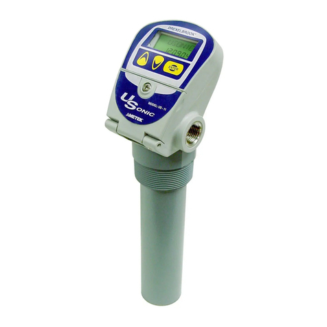
Ametek Drexelbrook Universal Lite 509-1 Series User manual

A Leader in
Level Measurement
For Assistance Call 1-800-527-6297
Outside Nort America + 215-674-1234
Installation and
Operating Instructions
Series 509-1X
Universal LiteTM Transmitter
wit HART® Protocol
using 409-1400 Electronics
+ 215-674-1234 Outside North America
1-800-553-9092 US and anada
www.drexelbrook.com

AMETEK Drexelbrook makes no warranty of any kind with regard to the material contained
in this manual, including, but not limited to, implied warranties or fitness for a particular
purpose. Drexelbrook shall not be liable for errors contained herein or for incidental or
consequential damages in connection with the performance or use of material.
Copyright 2007AMETEK Drexelbrook

Series 509-1X
Universal LiteTM Transmitter
wit HART® Protocol
using 409-1400 Electronics
EDO#01-07-108
409-1400-LM
Issue #6
205 Keith Valley Road Horsham, PA 19044
US Sales
1-800-553-9092
24 Hour Service
1-800-527-6297
International
+ 215-674-1234
Fax
+ 215-674-2731
E-mail
drexelbrook.inf[email protected]
Web
www.drexelbrook.com
An ISO 9001 Certified Company
DREXELBROOK


Table of Contents
SECTION 1 INTRODUCTION .........................................................................................................1
1.1 General Description ...................................................................................................................1
1.2 Technology .................................................................................................................................1
1.2 Models Available.........................................................................................................................2
1.2.1 Classifications ................................................................................................................4
1.2.2 Remote Electronic Unit...................................................................................................4
SECTION 2 INSTALLATION ............................................................................................................5
2.1 Unpacking ..................................................................................................................................5
2.2 Installation Guidelines ................................................................................................................5
2.3 Wiring Electronic Unit...............................................................................................................11
2.4 Wiring Sensing Element ...........................................................................................................12
2.5 Spark (Static Electricity) Protection ........................................................................................13
2.6 Surge Voltage Protection ..........................................................................................................15
2.7 RFI (Radio Frequency Interference) Filters..............................................................................15
2.8 Display/Keypad ........................................................................................................................17
SECTION 3 OPERATION...............................................................................................................18
3.1 Modes of Operation..................................................................................................................18
SECTION 4 CALIBRATION WITH DISPLAY/KEYPAD (Blue section)........................................19
4.1 Application Code ......................................................................................................................19
4.2 Configuration ............................................................................................................................19
4.2.1 Using Keypad ...............................................................................................................20
4.2.2 Set Decimal Position.....................................................................................................20
4.2.3 Set the Display Scale ...................................................................................................20
4.3 Calibration ................................................................................................................................22
4.4 Diagnostic Menu.......................................................................................................................24
4.4.1 Adjust Meter Trim ..........................................................................................................24
4.4.2 Time Delay ...................................................................................................................25
4.4.3 Software and Hardware Version Number .....................................................................27
4.4.4 Real time Capacitance Values......................................................................................27
4.4.5 Load Factory Default Setting ........................................................................................27
4.4.6 Scaled Percent Output .................................................................................................27
4.4.7 Application Code ..........................................................................................................28
4.4.8 Return to Main Menu ....................................................................................................28
SECTION 5 TROUBLESHOOTING ...............................................................................................29
5.1 Identifying a Problem ................................................................................................................29
5.2 Troubleshooting the Loop Connection ......................................................................................33
5.3 Model 275 Calibrator cannot identify or find device..................................................................34
5.4 Universal Lite Electronic Unit does not communicate with Drexelbrook
PC software .............................................................................................................................35
5.5 Troubleshooting Electronic Unit ................................................................................................36
5.5.1 Electronic Unit Drift Test ...............................................................................................37
5.6 Troubleshooting Sensing Element ............................................................................................37
5.7 Troubleshooting Coaxial Cable .................................................................................................39
5.8 Static Electricity .......................................................................................................................40
5.9 Radio Frequency Interference..................................................................................................40
5.10 Factory Assistance ..................................................................................................................42

Table of Contents (continued)
SECTION 5 TROUBLESHOOTING (continued)
5.11 Field Service ............................................................................................................................42
5.12 Customer training .....................................................................................................................42
5.13 EquipmentReturn.....................................................................................................................43
SECTION 6 SPECIFICATIONS ......................................................................................................44
6.1 Transmitter Specifications ........................................................................................................44
6.2 Coaxial Cable Specifications....................................................................................................45
APPENDIX A CALIBRATION WITH DREXELBROOK PC SOFTWARE
(Yellow section) ......................................................................................................................A-1
A.1 General Description ............................................................................................................... A-1
A.2 Model Number ........................................................................................................................A-1
A.3 System Requirements............................................................................................................A-2
A.4 InstallingModem.....................................................................................................................A-3
A.5 Installing Software on Hard Drive...........................................................................................A-3
A.6 Description of Function Keys .................................................................................................A-5
A.7 Configuration ..........................................................................................................................A-6
A.7.1 LevelConfiguration.....................................................................................................A-6
A.7.2 Vessel Configuration................................................................................................... A-7
A.7.3 Lower and Upper RangeValues (LRV and URV) .........................................................A-8
A.8 Calibration ..............................................................................................................................A-8
A.8.1 Point Calibration........................................................................................................A-10
A.8.2 LevelCalibration ....................................................................................................... A-10
A.8.3 Application Example....................................................................................................A-11
A.9 PC Status Messages ...........................................................................................................A-12
A.10 Set D/A Trim .........................................................................................................................A-13
A.11 StrappingTable .....................................................................................................................A-14
A.12 DigitalIntegralMeterConfiguration ......................................................................................A-15
A.13 Save/Print Entries ................................................................................................................A-17
A.14 Validation ..............................................................................................................................A-17
A.14.1 Design Concept .......................................................................................................A-17
A.14.2 Procedures ..............................................................................................................A-18
A.14.3 Results.....................................................................................................................A-19
APPENDIX B CALIBRATION WITH MODEL 275 CALIBRATOR WITH DREXELBROOK DE-
VICE DESCRIPTION (Pink section) ........................................................................................B-1
B.1 Drexelbrook Device Description ............................................................................................B-1
B.2 Start-up ..................................................................................................................................B-2
B.3 Configuration ..........................................................................................................................B-3
B.4 Calibration ..............................................................................................................................B-4
B.4.1 Point Calibration..........................................................................................................B-5
B.4.2 Capacitance Calibration .............................................................................................B-6
B.4.3 D/ATrim ......................................................................................................................B-7
B.4.4 StrappingTable ...........................................................................................................B-8
APPENDIX C CONTROL DRAWINGS.........................................................................................C-1
C.1 KEMA/CENELEC Drawings ..................................................................................................C-1
C.2 FM Drawings..........................................................................................................................C-3
C.3 CSA Drawings .......................................................................................................................C-8

509-1X Series Universal LiteTM
1
The instructions in this manual are for the AMETEK
Drexelbrook Universal LiteTM instrument, used for level
measurement in liquids, slurries, interfaces and granulars.
Each AMETEK Drexelbrook Universal LiteTM instrument
consists of:
••
••
•409-1400 series two-wire, 4-20mA electronic unit (transmitter)
••
••
•700 series sensing element (probe), and
••
••
•380 series connecting cable is also supplied for remote
connection of the sensing element to the electronic unit.
The Universal LiteTM instrument is a capacitance-to-current
transducer. A change in level produces a change in
capacitance causing a corresponding change in current
(4-20 mA). It is called a two-wire transmitter because the
same two wires that are used to power the unit also indi-
cate the change in level.
Universal LiteTM is uniquely provided with three frequen-
cies to produce a signal. Based upon the intended applica-
tion, the instrument is factory set to the frequency best
suited:
••
••
•100kHz which is standard for typical uses.
••
••
•15kHz which provides stability in low conductivity liquids.
••
••
•400kHz which is especially useful in measuring the
location of fluid interfaces. This frequency can also be
helpful to offset some of the negative effects of coatings.
These frequencies may be changed in the field if the appli-
cation is changed from the original intention. The selec-
tion is password protected to prevent an inadvertent
change which can disturb performance.
User may choose to configure the Universal LiteTM manu-
ally with a keypad, or by using the Drexelbrook PC soft-
ware.
SECTION 1
INTRODUCTION
1.1 General Description
1.2 Technology
Figure 1-1
Simple Capacitance Probe
(Insulating Media Shown)
k
k
air
A
d
Ck
media
C=kA
d
C = k A
d
A
k
air
d
C
k
media

509-1X Series Universal LiteTM
2
System model number is 509-001X-XXX. Electronic Unit
model number is 409-1400-0X. Sensing Element model
number is 700-XXXX-XXX.
5 0 9 - 0 0 1 X - X X X Universal LiteTM
Application:
5 = conductive liquids
6 = interface Sensing Element
7 = insulating liquids Reference Number:
9 = granular solids See Table 1-1
Package:
7 = Remote
9 = Integral
40 9 - 1 4 0 0 -X X X - 0 X Universal Lite
Electronic Unit
Agency Approvals: Display/Keypad:
F = FM 0 = without display/keypad
C = CSA 1 = with display/keypad
K = KEMA
0 = All above
Housing:
1 = Chassis Only
Frequency: 4 = Remote Type 4 X
0 = Standard Explosionproof
1 = Low with ¾-inch NPT
2 = High15 = Integral Type 4X
Explosionproof
with viewport
and 1-inch NPT
6 = Remote Type 4X
with Drexelcote
and ¾-inch NPT
8 = Integral Type 4X
with Drexelcote
and ¾-inch NPT
9 = Integral Type 4X
Explosionproof
with ¾-inch NPT
C = Integral Type 4X
Explosionproof
with 1-inch NPT
D = Integral Type 4X
Explosionproof
with Drexelcote
with 1-inch NPT
E = Remote Type 4X
Explosionproof
with viewport
and ¾-inch NPT
F = Integral Type 4X
Explosionproof
with viewport
and ¾-inch NPT
______________
1409-1400-02X is available with integral mounting only
(X= 5, 8, 9, C, D, or F).
1.2 Models Available

509-1X Series Universal LiteTM
3
Sensing Typical Sensing Standard OD and Temperature &
Element Application Element Material of Standard Pressure Limits
Reference Type Model Construction Mounting
Number Number
509-001X-
X02 Conducting 700-2-27 FEP-covered Rod 100oF @ 1000 PSI
liquids and rod .56" OD 300oF @ 500 PSI
interfaces 3/4" NPT
X06 Conducting 700-2-57 X-covered1Rod 100oF @ 1000 PSI
liquids and rod .84" OD 250oF @ 500 PSI
interfaces 1" NPT
X09 Water-like 700-1-22 TFE-covered Rod 3/8" OD 100oF @ 1000 PSI
conductive rod 3/4" NPT 300oF @ 500 PSI
liquids
X13 Agitated 700-5-18 X-covered1Cable 100oF @ 1000 PSI
X20 conducting cable 5/16" OD 250oF @ 500 PSI
liquids and 3/4" NPT
granulars
X16 Insulating 700-1-26 TFE-covered Rod 100oF @ 1000 PSI
liquids concentric rod 1 5/8" max OD 300oF @ 500 PSI
1 1/2" NPT
X25 Conducting 700-5-54 PFA-covered Cable 300oF @ 500 PSI
liquids cable .093" OD
3/4" NPT
X55 Insulating 700-1202-1 AWMP 316SS Cable 450oF @ 200 PSI
liquids T12 insulation 3/8" OD
.875 max OD
3/4" NPT
X85 Conducting 700-5-85 FEP-covered Cable 200oF @ 200 PSI
liquids cable .185" OD
3/4" NPT
1X is a fluorocarbon-type insulation
Table 1-1
Sensing Element
Model Numbering

509-1X Series Universal LiteTM
4
The standard electronic unit in a Type 4X housing meets
the following classifications:
••
••
•Type 4X Watertight/Corrosion Resistant.
The standard electronic unit mounted in the
explosionproof housing is dual-rated and meets the
following classifications:
••
••
•Type 4X Watertight/Corrosion Resistant.
••
••
•Explosionproof FM Approved for:
Class I Groups A,B,C & D;
Class II Groups E, F, & G;
Class III.
The remote electronic unit and sensing element are
connected by:
••
••
•Three-terminal coaxial cable (380-0XXX-01X):
- general purpose (-12);
- high temperature (-11);
- composite-first 10 feet high temperature (-18).
••
••
•The XX in the model number indicates the length of
the cable in feet.
••
••
•Standard length is 25 feet (e.g. 380-025-12).
••
••
•Maximum length is 50 feet.
••
••
•Cable can also be purchased in bulk lengths with
termination kits.
See Table 1-1 for detailed specifications of sensing
elements that are most often recommended with the
Universal Lite instrument. Contact the factory or your
local representative if additional information is required.
1.2.1 Classifications
1.2.2 Remote Electronic
Unit

509-1X Series Universal LiteTM
5
Carefully remove the contents of the carton and check
each item against the packing list before destroying any
packing material. If there is any shortage or damage,
report it immediately to the factory.
The Universal Lite (409-1400) instrument is designed for
field mounting, but it should be mounted in a location as
free as possible from vibration, corrosive atmospheres,
and any possibility of mechanical damage. For conve-
nience at start-up, mount the instrument in a reasonably
accessible location. Ambient temperatures should be
between –40°F and 185°F (–40°C and 85°C).
NOTE
When installing conduit to the electronic unit,
be sure that vertical conduit runs will not cause
water to enter the electronic unit housing, as
shown in
Figure 2-1
.
Figure 2-1 shows the recommended conduit installation.
See Figure 2-2 for dimensions when installing conduit to
the electronic unit.
Figure 2-1
Recommended Conduit Connection
SECTION 2
INSTALLATION
2.1 Unpacking
2.2 Installation
Guidelines
NOTE
Always install to NEC®
and/or local requirements/
codes/directives as mandated
by the authority having
jurisdiction.
NOTE
Cable fittings supplied are
weather-resistant. They are
NOT certified as explosionproof
(XP) or flameproof (d) unless
they are specifically marked.
NOTICE
NOTICE
NOTICE
WRONG CORRECT
CONDUIT
BREATHER
DRAIN
WRONG CORRECT
**
Allows Moisture Infiltration Use only cable
supplied by
AMETEK
Drexelbrook
All conduit connections
are sealed.
Gaskets are in place.
Fill Pipe Ends with
silicone sealant.
*
NOTE:
For electronic units with
display option, meter
display can be rotated to
proper viewing orientation
after installation. Refer to
Section 2.15
for instructions.
NOTICE

509-1X Series Universal LiteTM
6
All dimensions in inches (mm)

509-1X Series Universal LiteTM
7
2.2 Installation
Guidelines
(continued)
The mounting location for the sensing element (probe) is
often determined by whether there is a suitable location
inside a vessel. An external side arm or stilling well can
be considered.
Use the following sensing element mounting and
installation instructions:
A. In applications requiring an insulated sensing
element, use particular care during installation.
There is always the danger of puncturing the
insulation, especially with the thin-walled probes.
B. Sensing elements should be mounted in such a
manner that they are not in the direct stream of a
filling nozzle or chute. If this is not possible, a de-
flecting baffle should be installed between the probe
and the fill.
C. Do not take the sensing element apart or
loosen the packing glands. Follow instructions in
Figure 2-3.
Figure 2-3
Installing the Sensing Element
CONDULET
PACKING
GLAND
ASSEMBLY
DO NOT
DISTURB!
HOLD HERE WHEN
TIGHTENING CONDULET
HOLD HERE TO INSTALL OR
REMOVE SENSING ELEMENT
FROM VESSEL
NOTICE

509-1X Series Universal LiteTM
8
D. Avoid installing the sensing element with any of the
common mistakes shown in Figure 2-4.
E. If a stilling well is used, ensure that vent holes are
large enough to allow free passage of both air and
process material. Holes should be 5/8" or larger, 120o
apart, every 2-3 feet along the length of the stilling
well.
Figure 2-4
Common Installation Mistakes
2.2 Installation
Guidelines
(continued)
PROBE
CONTACTS
SIDE OF
STILLING WELL
SLUDGE
SLUDGE
MAY CLOG
PIPE
LACK OF PROPER GROUND
(EARTH) CONNECTION
BETWEEN SENSOR MOUNTING
AND VESSEL WALL
NOZZLE DIAMETER TOO
SMALL OR LENGTH TOO
LONG
DAMAGE
MAY
OCCUR
HERE
DAMAGE
MAY
OCCUR
HERE
PROBE
MAY
FLEX
INSIDE
PIPE
FILL LINE
AVOID
FILL
STREAM
WALL BUILD-UP
TOUCHES SENSOR
STILLING
WELL
LACKS
VENT
HOLES

509-1X Series Universal LiteTM
9
F. Sensing elements that are mounted in agitated vessels
usually require brackets and supports to control the
position of the sensor during agitation. See Figure 2-5.
2.2 Installation
Guidelines
(continued)
FLEXIBLE
BOTTOM
ANCHOR
PART# 727-XX-X
CUSTOMER
SUPPLIED
SUPPORT
RECOMMENDED FLEXIBLE
SENSOR INSTALLATION
FLEXIBLE
CABLE TYPE
SENSOR
ROD
STYLE
SENSOR
CUSTOMER
SUPPLIED
SUPPORT
BRACKET
INSULATED
SUPPORT
BUSHINGS
PART # 713-XX-X
RECOMMENDED RIGID
SENSOR INSTALLATION
AVOID WEIGHTED
FLEXIBLE SENSORS IN
HEAVILY AGITATED
VESSELS
Figure 2-5
Installing a Sensing Element
in an Agitated Vessel

509-1X Series Universal LiteTM
10
G. For non-metallic vessels without Drexelbrook self-
grounding sensing elements, choose one of the ground-
ing recommendations shown in Figure 2-6.
2.2 Installation
Guidelines
(continued)
RUN APPROXIMATLY A 14 GA.
WIRE FROM GREEN GROUND
EARTH) SCREW TO THE
CHOSEN GROUNDING
EARTHING) METHOD 1,2,3,OR 4.
NOTE: BE SURE THAT
GROUNDING METAL IS
COMPATIBLE WITH PROCESS
MATERIAL
METAL PIPE - METAL PIPING
ENTERING THE TANK CAN BE
USED AS A GROUND. USE
ONLY IF PROCESS MATERIAL
HAS A CONDUCTIVITY
GREATER THAN 1000 uMHOS/
CM.
GROUNDROD
METAL, PIPE OR TUBING PARALLEL
AND RELATIVELY CLOSE TO PROBE.
GROUND ROD MUST BE
COMPATIBLE WITH PROCESS
MATERIAL
GROUND
CLAMP
GROUND CLAMP
TO CONDULET
GROUND SCREW
TO CONDULET
GROUND SCREW
NON
METALLIC
TANK
GROUNDING CABLE
1/4 INCHSTAINLESS
STEEL GROUND WIRE
WITH WEIGHT
TO CONDULET
GROUND SCREW
PROBE
CONDULET
TOP VIEW
METALLIC OBJECT
USE FLANGE OR METAL
ORIFICE PLATE. USE ONLY IF
PROCESS MATERIAL IS
GREATER THAN 1000
uMHOS/CM. SUCH AS ACIDS
AND CAUSTIC
!
"
Level
Sensor
Figure 2-6
Providing a Ground Reference1
1This is a sensing element ground reference and possibly different from an electrical power ground

509-1X Series Universal LiteTM
11
2.3 Wiring
Electronic Unit
Figure 2-7
Universal Lite Wiring Connections - Integral Mounting
NOTES:
1. All devices must be wired in series.Voltage driven devices
require a series voltage dropping resistor.
2. HCC signal terminals V+ and V- can operate with a
minimum of 13.0 Vdc with 20 mA flowing.
3. If the field wiring is to be in hazardous areas, then suitable
safety barriers are required between the power supply and
the field to provide for intrinsically safe field wiring.
Two-terminal
Sensing Element
Three-terminal
Sensing Element
RFI filter required for CE mark-
certified installations.See Figure
2-14 for wiring connections.
Figure 2-8
Universal Lite Wiring Connections
Remote Mounting with Coax Cable
Integral units are pre-wired at the factory. Figure 2-7 shows
the wiring of the integral unit.
Signal loop connections are made to HCCV+and V– terminals
onthew four-terminal block on front of chassis. Due to low
power consumption of the instrument, wiring need only be
light gauge (e.g. 20 AWG). Twisted shielded pair cables are
recommended for lengths over 200 feet.
Cable from sensing element is connected to the three-termi-
nal strip on backside of chassis. Cable connections are PROBE
(blue lug wire), GND (green lug wire), and SHD (red lug wire).
See Figure 2-8 for wiring connections of remote unit.

509-1X Series Universal LiteTM
12
Figure 2-9
Three-Terminal Cable Connections to Two-Terminal Sensing Element
Only coaxial cables supplied by AMETEK Drexelbrook
should be used to connect transmitter to sensing element.
Use of other cables can result in unstable calibration.
CAUTION
Before using Intrinsic Safety Barriers, read
the manufacturer's instruction for barrier
operation.
The 409-1400 has a built-in current limiter which holds
the signal current to a maximum of 28 mA.
The cable connections to the sensing element are shown in
Figures 2-9 and 2-10.
••
••
•Do not connect the cable to the sensing element until
after the sensing element has been installed in the ves-
sel and the condulet housing has been secured.
••
••
•If the sensing element does not have a shield connection,
(the most common condition for a 2-terminal sensing
element) be sure to clip and tape the shield wire at
the sensing element end of the cable only. See
Figure 2-9.
2.4 Wiring
Sensing Element
Figure 2-10
Three-Terminal Cable Connections to Three-Terminal Sensing Element
NOTE:
Clipped Shield wire on two-wire
versions must NOT touch housing.
NOTICE
NOTICE

509-1X Series Universal LiteTM
13
2.5 Spark (Static
Electricity)
Protection
—Spark Protection for Integral Sensing Elements
If spark protection is supplied for an integral sensing
element, use the following instructions for installing the
spark protection.
a. Attach the mounting link on the spark protector to the
sensing element center connection screw.
b. Connect the green lug wire from the spark protector to
the housing/chassis mounting screw.
c. Connect the center wire connector (blue lug wire) of the
spark protector to the PROBE connection on the
electronic unit.
d. Connect the shield connector (red lug wire) of the
spark protector to the SHD connector on the electronic
unit.
Figure 2-11
Spark Protection for Integral Sensing Elements
NOTE
Make sure that transmitter
has a ground attached either
on sensing element side or
loop side of the unit. Unless
assembly is attached to a
metalic vessal, chassis of
transmitter is not grounded.
NOTICE

509-1X Series Universal LiteTM
14
—Spark Protection for Remote Sensing Elements
If spark protection is supplied for a remote sensing ele-
ment, use the following instructions for installing the
spark protection.
a. Attach the mounting link on the spark protector to the
sensing element center connection screw.
b. Connect the green wire from the spark protector to the
ground screw.
c. Feed the coax cable into the condulet.
d. Connect the coax cable center wire (CW) to the spark
protector and the ground wire (GND) to the ground
screw as shown in Figure 2-12.
e. Connect the shield wire to the Cote-Shield terminal
(SH).1
1For sensing elements that do not have shield connections,
clip and tape the shield wire as shown in Figure 2-9.
2.5 Spark (Static
Electricity)
Protection
(continued)
Figure 2-12
Spark Protection for Remote Sensing Elements
NOTE:
Clipped Shield wire on
two-wire versions must
NOT touch housing.
NOTICE
Table of contents
Other Ametek Drexelbrook Transmitter manuals
Popular Transmitter manuals by other brands

Everflourish
Everflourish EMW202T-1 instruction manual

Minicom
Minicom 1VS22031 Quick installation guide

ABB
ABB PGX100 Operating instruction

Utilimaster
Utilimaster UAS P Series troubleshooting guide

Hama
Hama Twin operating instructions

Dwyer Instruments
Dwyer Instruments 608 Series Specifications-installation and operating instructions