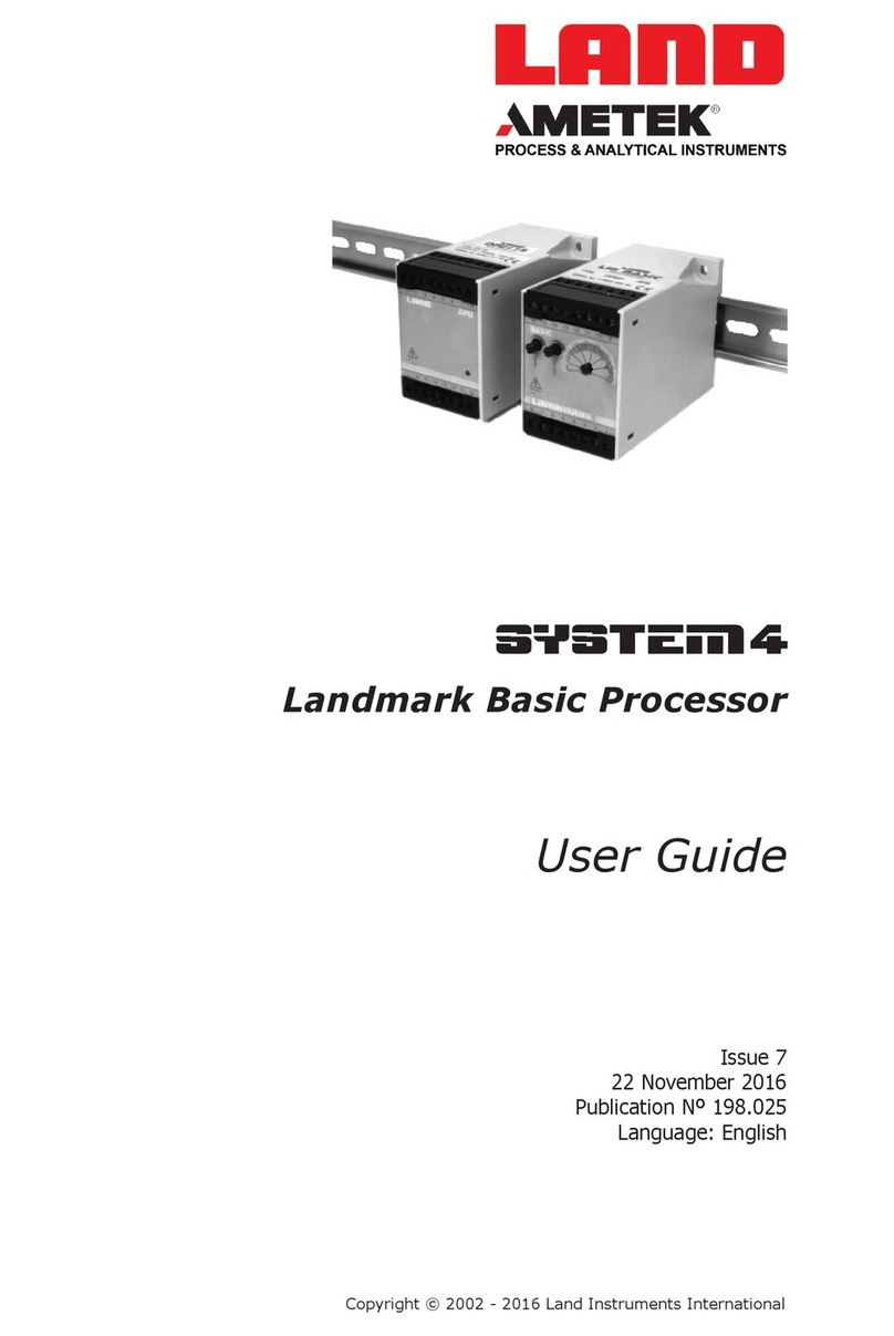
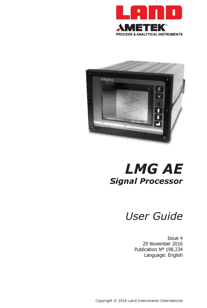
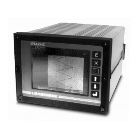
Ametek Land LMG MkII User manual

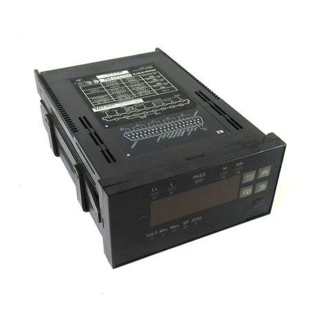
Landmark Graphic MkII Signal Processor
i
QUALITY CUSTOMER SOLUTIONS
LMG MkII
USER GUIDE
PUBLICATION NO812471
LANGUAGE: ENGLISH

Health and Safety Information
Read all of the instructions in this booklet - including all the WARNINGS and CAUTIONS
- before using this product. If there is any instruction which you do not understand, DO
NOT USE THE PRODUCT.
Safety Signs
WARNING
Indicates a potentially hazardous situation which, if not avoided, could result in death or
personal injury.
CAUTION
Indicates a potentially hazardous situation which, if not avoided, could result in minor or
moderate injury to the user or users, or result in damage to the product or to property.
NOTE
Indicates a potentially hazardous situation which, if not avoided, could result in damage or the loss of
data.
Signs and Symbols used on equipment and Documentation
Caution, risk of electric shock.
Caution, attention to possibility of risk of damage to the product, process or surroundings. Refer
to instruction manual.
Caution, hot surface.
Protective Conductor Terminal.
Observe precautions for handling electrostatic discharge sensitive devices.
Equipment Operation
Use of this instrument in a manner not specied by AMETEK Land may be hazardous. Read and
understand the user documentation supplied before installing and operating the equipment.
The safety of any system incorporating this equipment is the responsibility of the assembler.
Protective Clothing, Face and Eye Protection
It is possible that this equipment is to be installed on, or near to, machinery or equipment operating at
high temperatures and high pressures. Suitable protective clothing, along with face and eye protection
must be worn. Refer to the health and safety guidelines for the machinery/equipment before installing
this product. If in doubt, contact AMETEK Land.
Electrical Power Supply
Before working on the electrical connections, all of the electrical power lines to the equipment must
be isolated. All the electrical cables and signal cables must be connected exactly as indicated in these
operating instructions. If in doubt, contact AMETEK Land.
Storage
The instrument should be stored in its packaging, in a dry sheltered area.
Minimum storage temperature = Minimum operating temperature - 10 °C (18 °F)
Maximum storage temperature = Maximum operating temperature + 10 °C (18 °F)
Refer to the Technical Specication for details of the operating temperature limits.
Unpacking
Check all packages for external signs of damage. Check the contents against the packing note.
Lifting Instructions
Where items are too heavy to be lifted manually, use suitably rated lifting equipment. Refer to the
Technical Specication for weights. All lifting should be carried out in accordance with local and national
regulations.
IMPORTANT INFORMATION - PLEASE READ
Contact Us
UK - Droneld
Land Instruments International
Tel: +44 (0) 1246 417691
USA - Pittsburgh
AMETEK Land, Inc.
Tel: +1 412 826 4444
China
AMETEK Land China Service
Tel: +86 21 5868 5111 ext 122
India
AMETEK Land India Service
Tel: +91 - 80 67823240
Email: [email protected]
Web: www.ametek-land.com
For further details on all AMETEK Land oces, distributors and representatives, please visit our website.
Return of Damaged Goods
IMPORTANT If any item has been damaged in transit, this should be reported to the carrier and to the
supplier immediately. Damage caused in transit is the responsibility of the carrier not the supplier.
DO NOT RETURN a damaged instrument to the sender as the carrier will not then consider a claim. Save
the packing with the damaged article for inspection by the carrier.
Return of Goods for Repair
If you need to return goods for repair please contact our Customer Service Department for details of the
correct returns procedure.
Any item returned to AMETEK Land should be adequately packaged to prevent damage during transit.
You must include a written report of the problem together with your own name and contact information,
address, telephone number, email address etc.
Design and Manufacturing Standards
The Quality Management System of Land Instruments International is approved to BS EN ISO 9001 for
the design, manufacture and on-site servicing of combustion, environmental monitoring and non-contact
temperature measuring instrumentation.
Registered ISO 9001 Management System approvals apply in the USA.
UK Calibration Laboratory: UKAS 0034.
USA Calibration Laboratory: ANAB Accredited ISO/IEC 17025.
National Accreditation Board for Testing and Calibration Laboratories approvals apply in India.
Operation of radio transmitters, telephones or other electrical/electronic devices in close proximity
to the equipment while the enclosure doors of the instrument or its peripherals are open, may cause
interference and possible failure where the radiated emissions exceed the EMC directive.
The protection provided by this product may be invalidated if alterations or additions are made to the
structural, electrical, mechanical, pneumatic, software or rmware components of this system. Such
changes may also invalidate the standard terms of warranty.
Copyright
This manual is provided as an aid to owners of AMETEK Land’s products and contains information
proprietary to AMETEK Land. This manual may not, in whole or part, be copied, or reproduced without the
expressed written consent of AMETEK Land.
Copyright © 2018 Land Instruments International.
MARCOM0311, Issue 10, 13 June 2018

Signal Processor
LMG MkII
Contents
1 Introduction 1-1
1.1 About this Guide 1-1
1.2 About the Processor 1-1
1.3 Specication 1-2
1.4 UnpackingtheProcessor 1-3
2 InstallingtheProcessor 2-1
2.1 InstallingtheProcessorinaPanel 2-2
2.2 ElectricalConnections 2-5
2.3 CableConnectorAssembly 2-10
2.4 FittinganI/Ocard 2-11
3 UsingtheProcessor 3-1
3.1 GettingStarted(accessingthemenusystem) 3-1
3.2 LanguageSelection 3-3
3.3 AbouttheChannelCongurationMenu 3-3
3.4 AdjustingitemsintheChannelCongurationMenu 3-4
3.5 Usingthe‘Quick’Buttons 3-5
3.6 ThermometerType 3-7
3.7 Emissivity 3-8
3.8 Alarms 3-9
3.9 Output 3-10
3.10 Label 3-10
3.11 DisplaySettings 3-11
3.12 ChangingtheAccessCode 3-21
4 TimeFunctionProcessing 4-1
4.1 None 4-1
4.2 Averager 4-1
4.3 PeakPicker 4-3
4.4 ValleyPicker 4-4
4.5 TrackandHold 4-5
5 SerialCommunications 5-1
5.1 SerialPortCommands 5-2
5.2 RS485Serialcommunicationdataformat 5-7
5.3 SystemCommunicationsTimingData 5-10

LMG MkII
Signal Processor
Contents (Continued...)
6 ExternalI/OMathsFunctions 6-1
6.1 ExtI/OMathsFunctionCardInstallationInstructions 6-1
6.2 MathsCardElectricalConnections 6-2
6.3 MathsFunctions 6-5
6.4 MathsFunctionOptions 6-7
6.5 AlarmandCurrentOutputConguration 6-14
6.6 TypicalMathsFunctionApplications 6-19
7 Maintenance 7-1
7.1 AvailableSpares 7-1
7.2 USBFunctions 7-2
8 UpgradingfromLMGMkItoLMGMkII 8-1
8.1 UpgradeProcedure 8-1
8.2 Dierences&Similarities 8-1

INTRODUCTION
1

1 - 1
LMG MkII
Signal Processor
User Guide
1Introduction
1.1 About this Guide
Thisguidegivesyoualltheinformationnecessaryforyoutosafelyinstall
andoperateaLandmarkGraphicMkIIsignalprocessor(LMGMkII).
Itcoverstheelectricalandmechanicalinstallation,touchscreendisplaysand
menusystem,explainsthesignalprocessingandmathematicalfunctionality
available,anddetailstheserialcommunicationsprotocol.
ThereisalsoasectiononupgradingfromaLANDSystem4Landmark
GraphicProcessor(LMG).
ElectroniccopiesofthisUserGuidecanbeobtainedfromtheLANDwebsite
www.ametek-land.com.
1.2 About the Processor
TheLMGMkIIsignalprocessorisdesignedtobeusedinconjunctionwith
AMETEKLandinfraredthermometers.Ithasbeendesignedasanupgrade
fromanoriginalLMGandcontainsmanyofthesamefeatures.
Theprocessorfeaturesinclude:
• Large,clear,brightfullcolourLCDtouchscreenwithwideviewingangle
• Easytousecongurationmenusystem,withsecuritycode,context-
sensitivehelpdisplayand‘QuickKey’selectionofthemostcommonly
changedparameters
• Languagechoiceforthedisplaytext
• Multi-channelforusewithuptofourconnectedthermometers
• Achoiceoftimefunctionprocessingoptionsforeachthermometerinput
• CurrentandvoltageretransmissionoutputforSCADAconnections
• Mathematicalcomputationofmulti-thermometeralgorithms,including
backgroundcompensation
• +24VdcPowerinput(separateDINrailpowersupplyformainsinputs)
• SerialcommunicationsasstandardinRS485format
• AfrontpanelcoverwhichprovidessealingtoIP65standards
Fig.1-1LandmarkGraphicMkIISignalProcessor

Signal Processor
LMG MkII
1.3 Specification
Model Landmark Graphic
Accuracy ±0.12%ofreading
Stability(Temp) 0.01%ofspan/°
Discrimination 0.015%offullscale
Display LEDlit,800x480pixels
Displayupdate 0.5sText,0.1sGraphics
Screens Numeric,linechart,deviationchart,4channelbargraph,4channeldeviationbar
graph
Line/Deviationchartranges 1°steps,100°minspan,setable
Bargraphranges 1°steps,100°minspan,setable
Timespan 1,3,6,12,30,60,90,270mins
Userlabel Upto10characters
Signal Outputs Tosuittemperaturerangeofthermometer
Current 0to20mAor4to20mA
Selectablerange 50°steps,100°minimumspan
Voltageoutput 1mV/°
Outputupdate 1.25ms
Thermometer
Thermometerinputupdate 1.25ms
Emissivity 0.050to1.000in0.001steps
(Note: below 0.200, system operation is unspecied and not guaranteed)
Nongreyness 0.800to1.250in0.001steps
Peak Picker Reset,holdorpeaksample,selectable
Threshold 1°steps,setable
Ondelay 0to10sin0.1ssteps
Odelay 0to10sin0.1ssteps
Decayrate 0,0.25,0.5,1,2,4,8,16,32,64,128,256,512°/s
Acquisitiontime 1.25ms
Valley Picker Reset,holdorvalleysample,selectable
Threshold 1°steps,setable
Ondelay 0to10sin0.1ssteps
Odelay 0to10sin0.1ssteps
Recoveryrate 0,0.25,0.5,1,2,4,8,16,32,64,128,256,512°/s
Acquisitiontime 1.25ms
Interval 10to250sin1ssteps
Averager
Timeconstant 0,0.05,0.1.0.15,0.25,0.5,1,2,4,8,16,32,64,128,256,512s
Track and Hold
Controlsignal 5to24Vdc.orswitch/relay
Responsetime 1.25ms
Alarms Highorlow,setable
Triplevel 1°steps,setable
Relaycontactrating 50Va.c.ord.c.at0.5A
Update 10ms
Hysteresis 3°
Power Supply
Powerrequirement
(LMGMkII)
24Vdc±10%,3AMax.
ExternalDINRailPSU
(supplied) 100-240Vac,50/60Hz,2.4Amax
Environment
Ambientoperatingtemp 5to50°C/40to120°F(specied)
5to60°C/40to140°F(max.operating)
Sealing ToIP65/NEMA4(withprotectioncovertted)
Humidity 0to99%noncondensing
Vibration 1gAnyaxis10to300Hz
EMC EN61326-1
RoHS 011/65/EUcompliant

1 - 3
LMG MkII
Signal Processor
User Guide
1.4 Unpacking the Processor
Thepackagecontainingtheprocessorwillcontainthefollowingitems:
• LandmarkGraphicMkIIProcessor
• 7-wayplug*andcover(including2screwsandaclampbar)for
connectiontotheThermometer
• 6-wayplug*forAlarmoutputconnection
• 5-wayplug*andcover(including2screwsandaclampbar)for
Retransmissionoutputconnection
• 2-wayplug*forCommandinputconnection
• 3-wayplug*for24Vdcpower
• DINRail-mountedPowerSupply24Vdcoutput,100to240Vacinput
• One2.5mmhexagonalscrewdrivertoaidinstallationandsetup
*Oneoftheseconnectorsissuppliedforeachthermometerchannelttedto
the processor.
Ifyouhaveorderedanyoptionalboards,thesewillbesuppliedpre-tted.
Checkthatyouhavebeensuppliedwithallordereditems.

INSTALLING THE
PROCESSOR
2

2 - 1User Guide
LMG MkII
Signal Processor
Fig.2-1ProcessorInstallationDimensions
Approximately 400 mm / 15.8 in required for card removal
Processor front bezel 144mm/5.7in
Mounting
panel
16 mm / 0.6 in
184 (+1.1, -0) mm
/ 7.2 (+0.04, -0) in
137 (+1, -0) mm
/ 5.4 (+0.03 -0) in
Cut-Out
Maximum panel thickness = 13 mm / 0.5 in
Processor front bezel 192mm/7.6in
Protection cover 206 mm / 8.1 in
Protection cover 158mm/6.2in
2Installing the Processor
TheLandmarkGraphicMarkIIprocessorisdesignedtobemountedinan
instrumentpanel.
TheoverallinstallationdimensionsoftheprocessoraregiveninFig.2-1.

User Guide2 - 2
Signal Processor
LMG MkII
2.1 Installing the Processor in a Panel
1) RefertoFig.2-1.Chooseanareaofyourmountingpanelofsucient
sizetocontaintheprocessor.
2) Carefullycutarectangularareaoutofthepanel184mm/7.2inwide,
by137mm/5.4inhigh.
3) RefertoFig.2-3.Unscrewthefourretainingscrewsontherearofthe
processorandslideoutthetwoclampbars.
4) Fromtheviewingside,inserttheprocessorinthemountingpanel.
5) Fromtherear,re-inserttheclampbarsintotheirchannelsandpush
themuptotouchthemountingpanel.
6) Insertandtightentheretainingscrewsuntilthemountingpanelis
rmlygrippedbetweentheprocessorfrontpanelandtheclampbar.
CAUTION
Donotovertightenthescrewsasthiswilldeformtheclampbar.
Clamp bar
Retaining screw
Mounting panel
Viewing side
Fig.2-2Mountingtheprocessorinapanel

2 - 3User Guide
LMG MkII
Signal Processor
Aclearcoverisavailable(PartNº812087),whichscrewsontotheprocessor
frontpanelandsealsittoaratingofIP65(SeeFig.2-3)
Fig.2-3LMGMkIIProcessorCover

User Guide2 - 4
Signal Processor
LMG MkII
Fig.2-4LMGMkIIElectricalSystemOverview

2 - 5User Guide
LMG MkII
Signal Processor
2.2 Electrical Connections
TheelectricalsystemoverviewosgiveninFig.2-4(opposite).
Theelectricalconnectionstoandfromtheprocessorareallmadevia
connectorsontherearpaneloftheprocessor.Fig.2-5showsthelocationof
the connectors.
Fig.2-5Rearpanelelectricalconnections
1
2
3
45
6
7
1Alarmoutput
2Commandinput(CMD)
3Retransmissionoutput
4Thermometerconnector
5 RS485serialcommunicationsoutput
6USBupdateport
7 Powerinput+24Vdc

User Guide2 - 6
Signal Processor
LMG MkII
Fig.2-7CMD(Command)cableconnectionschedule
Thecommandinputcanbecontrolledviaaremoteswitch/relaycontact,as
showninFig.2-8.
2.2.1 Alarm output connection schedule
TheAlarmoutputconnectionscheduleisgiveninFig.2-6.
TheAlarmrelaycontactratingis50Vacordcat0.5A.
Thealarmrelayswillbeintheir‘Alarm’statewhenpowerisremoved.
Fig.2-6Alarmcableconnectionschedule
2.2.2 CMD (Command) input connection schedule
TheCMD(Command)inputconnectionscheduleisgiveninFig.2-7.
Thecommandsignalisinactivewhenthevoltageis>3.0Voropencircuit
(i.e.Track)
Thecommandsignalisactivewhenthevoltageis<1.5Vorshortcircuit(i.e.
Hold).
Fig.2-8CMD(Command)inputcontrolviaaremoteswitch/relaycontact
ALARMS
Pin Nº Function
C
NO
NC
C
NO
NC
Description
Common
Normally Open
Normally Closed
Common
Normally Open
Normally Closed
Alarm 1
Alarm 2
1
2
3
4
5
6
Pin Nº Function
CMD+
CMD-
Description
Command input drive
Command input return
1
2
CMD
1
2
CMD
Remote switch /
Relay contact
Vin
Switch open
Peak Picker Track & Hold
Switch closed
Peak Pick
Reset
Track
Hold
+
-

2 - 7User Guide
LMG MkII
Signal Processor
2.2.3 Output (Retransmission output) connection schedule
TheOutput(Retransmissionoutput)connectionscheduleisgiveninFig.2-9.
Fig.2-9Retransmission‘Output’cableconnectionschedule
2.2.4 Thermometer connection schedule
ThethermometerconnectionscheduleisgiveninFig.2-10.
Fig.2-10Thermometerconnectionschedule
2.2.5 Serial Communications connection schedule
TheRS485optionalserialcommunicationsoutputconnectionscheduleis
giveninFig.2-11.
Fig.2-11SerialCommunicationscableconnectionschedule
Pin Nº Function
I +
I -
Screen
V +
V -
Description
Current output drive
Current output return
Screen
Voltage output drive
Voltage output return
Maximum loop
resistance: 500 Ω
1
2
3
4
5
OUTPUT
Load
Minimum load
resistance: 10k Ω
Yellow
Blue
White
Screen
Red
Black
Green
Function
Cable Colour
T+
T-
E+
Screen
V+
V-
E-
Pin Nº
1
2
3
4
5
6
7
THERMOMETER
T Temperature signal
from thermometer
E Emissivity signal to
thermometer
V Power supply to
thermometer
FunctionPin Nº
GND
Tx+
Tx-
Screen
Rx-
1
2
3
4
5
6
RS 485
Rx+
Use Pins 2 to 6 if
connecting an existing
LMG RS485 connector
120Rtermination
resistorsareavailable
onthePCB.Remove
thebackpaneland
slidethecardoutto
access.

User Guide2 - 8
Signal Processor
LMG MkII
2.2.7 DC power input
ThedcpowerinputconnectionscheduleisgiveninFig.2-13.
FunctionPin Nº
SCR
0V
+24V
Fig.2-13DCpowerinputconnectionschedule
Fig.2-14DCpowerinputfromPowerSupply
2.2.6 USB Upgrade Port
ConnectaUSBstickwiththelatestrmwareforboth
ProcessorandI/OCardstotheUPGRADEPort(Fig.2-12).
TheLMGMkIIsoftwarewillupdateautomaticallyfromthe
lesontheUSB.
SeeSection7.2forinstructionsonupdatingthermware.
Fig.2-12
UPGRADEport

2 - 9User Guide
LMG MkII
Signal Processor
2.2.8 RS485 connections
ThesignalsavailableontheRS485connector,ontherearpanelofthe
LandmarkGraphicMkIIProcessor,areshowninFig.2-15.
Fig.2-15RS485interfaceconnectoronrearpanelofprocessor
Fig.2-16RS485interfaceconnections
RS485 converter
USB USB
Tx-
Tx+
GND
Rx-
Screen
n
n
n
n
n
1
3
2
4
5
Rx+
Rx-
Rx+
GND
Tx-
Tx+ 6
*Remove rear cover of LMG MkII to access S1.
LMG MkII isolated RS485 with
optional* 120R termination
LMG
1234 S1
120R 120R
PC with RS485 converter
Isolation
LMG MkII RS485
6-way connector
FunctionPin Nº
GND
Tx+
Tx-
Screen
Rx-
1
2
3
4
5
6
RS 485
Rx+
Use Pins 2 to 6 if
connecting an existing
LMG RS485 connector

User Guide2 - 10
Signal Processor
LMG MkII
Fig.2-17Correctcablewiringarrangement
Keep wire length as
short as possible
Ensure cable's outer insulation
is held in clamp bar/cable tie
Clamp bar
Themaximumcablelengthsare,toagreatextent,dependentonbaudrate
andcabletype.Generallyalowerbaudratewillgivereliablecommunications
overalongerlengthofagivencabletype.
RS485 9600baud,1000mwhenusingthecablerecommendedbelow,
withcorrectcableterminations.
Recommended1000mcableforRS485:
• 2pairsindividuallyscreened
~50ohmscharacteristicimpedance,<=55ohm/km
<100pf/mcoretocore
<200pf/mcoretoscreen
2.3 Cable Connector Assembly
Thecableconnectorsfortherearpaneloftheprocessorareincludedinthe
processorpackage.Eachcableconnectormustbecorrectlywiredwiththe
appropriatecablebeforetheprocessorisused(RefertoSection2.2forthe
cableschedules).A‘writeon’labelisincludedintheconnectorforyouruse.
Towireuptheconnector.
1) Makeanoteoftheconnector’sorientationintherearpanelofthe
processor.
2) Unclipthetwohalvesoftheconnectorshelltorevealtheterminalblock
andthecabletie/clampbar.
3) Wireuptheconnector,rememberingthecorrectorientationoftheplug,
inaccordancewiththerelevantcableschedule(seeSection2.2).
NOTE
Keepwirelengthasshortaspossible,especiallyforanyscreen
connection.
4) Ensurethatthecableouterinsulationisheldintheclampbar/cabletie
attheconnectorandtightentheclampbarscrews/cabletie.Referto
Fig.2-17.
Table of contents
Other Ametek Land Signal Processor manuals