Ametek SURAGEX AXESS Reasy FLATPAK SA-82-AR Manual

SA-82-AR
Hardware Installation
Guide
FIRMWARE VERSION: 1.20.261
SOFTWARE VERSION: 2.00.03
© 2019 AMETEK Electronic Systems Protection | Technical Support: 1-800-645-9721 | UM-SA-82-AR-Rev-D

© 2019 AMETEK Electronic Systems Protection | Technical Support: 800-645-9721 | surgex.com
1
SA-82-AR User Manual
_________________________________________________________________________________________
I. INTRODUCTION 2
II. INSTALLATION 3
1. ETHERNET CONNECTION 3
2. AC POWER CONNECTIONS 3
3. LED INDICATORS 3
III. INITIAL SETUP 4
1. DEVICE MANAGEMENT UTILITY (DMU) 4
2. SETTING THE IP ADDRESS 5
IV. OUTLET ON LED INDICATOR 6
V. WEB SERVER 7
1. PASSWORD 7
2. CONTROL AND STATUS PAGE 7
3. SETUP PAGES 8
DEVICE 8
NETWORK 9
ADVANCED NETWORK 10
AUTOPING 11
SCHEDULE 13
PASSWORD 14
VI. COMMAND LINE INTERFACE (CLI) PROTOCOL 15
1. PROMPTS 15
2. CONTOL COMMANDS 15
3. DEVICE COMMANDS 15
4. NETWORK COMMANDS 16
5. AUTOPING COMMANDS 17
6. USER COMMANDS 17
7. EVENT COMMANDS 18
VII. DxP PROTOCOL 19
1. OVERVIEW 19
2. HELLO HANDSHAKE 19
3. DXP PACKET 20
4. COMMANDS 21
5. DESCRIPTERS 21
6. PAYLOADS 23
VIII. FIRMWARE UPGRADES 23
IX. RESET BUTTON 24
X. SPECIFICATIONS 25

© 2019 AMETEK Electronic Systems Protection | Technical Support: 800-645-9721 | surgex.com
2
SA-82-AR User Manual
_________________________________________________________________________________________
I. Introduction
The SurgeX® SA-82-AR is a network attached, IP addressed, web-controlled AC surge protector and power
conditioner. The SA-82-AR may be used to switch up to 8A at 120V. The simple web server structure allows
basic control of two outlets. The extensive programming and setup capabilities are accessed by a web browser,
through a Device Management Utility (DMU), or through a Command Line Interface (CLI).
•
The SA-82-AR features SurgeX® Series Mode® surge protection, Impedance
Tolerant EMI/RFI filtering and Over-Voltage Shutdown.
•
Remote reboot any device: monitors, routers, servers, kiosks, etc. The remote device need not be
network attached.
•
Conserve energy by powering down equipment when not in use.
•
Telnet access uses the Command Line Interface (CLI) structure and syntax to completely configure and
control the SA-82-AR. This Axess Ready (AR) device also supports the DxP protocol, which allows
software developers to integrate the unit into custom applications.
•
Up to 2 systems can be continuously monitored with AutoPing,with automatic power control upon loss
of contact. Reboot crashed systems or provide auto power-up, or - down for environmental controls and
notification systems.
•
The SA-82-AR utilizes 2 levels of password security, with only the administrative account having access to
setup and configuration.
Located on the rear panel are the input IEC power plug, network connection (RJ-45), 8A circuit breaker, and output
receptacles.
The front panel contains the Outlet On LED, Self-Test LED, System On LED, and Reset button.

© 2019 AMETEK Electronic Systems Protection | Technical Support: 800-645-9721 | surgex.com
3
SA-82-AR User Manual
_________________________________________________________________________________________
II. Installation
1. Ethernet Connection
The RJ45 connector for 10/100 Ethernet is situated on the rear panel beside
the input power plug. The default IP Address is DHCP assigned. The fallback IP
address is 192.168.1.254.
2. AC Power Connections
Connect the device to be powered On and Off to the output duplex receptacle.
Ensure that the total combined load of all controlled devices does not exceed 8
Amps.
Connect one end of the supplied power cord to the connector labeled “AC Input”,
and the other end to a properly grounded AC outlet.
3. LED Indicators
The green Self-Test LED indicates that the internal surge protection circuitry is
fully functional. The red Outlet On LED indicates that power is being supplied to
the two receptacles.
The red System On LED indicates that the Axess system is On. This indicator will turn off if the AC voltage rises above
145V, and AC power will be removed from the output receptacles in order to protect connected equipment. When
the AC voltage returns to below 135V, power will automatically be restored to the output receptacles and the System
On LED will turn on.

© 2019 AMETEK Electronic Systems Protection | Technical Support: 800-645-9721 | surgex.com
4
SA-82-AR User Manual
_________________________________________________________________________________________
III. Initial Set-Up
1. Device Management Utility (DMU)
The SurgeX Device Management Utility (DMU) provides the
easiest means to find and configure your AR for use. The DMU
can:
1. Automatically discover multiple ARs on a local
network.
2. Display the current IP address of each AR.
3. Allow the setting of a new IP address for each AR.
4. Perform firmware upgrades.
5. Return an AR to Factory Defaults.
The SurgeX Device Management Utility is available on the
SurgeX website at http://www.surgex.com
Note: The IP address can only be set within the first
2 minutes after powering up the AR. The utility will only work with
ARs on the same local subnet as the PC.
Device
Discover: Automatically discover all ARs on the local
network. The DMU will display the location name
of the AR, the product ID and version number, the
current IP address, and the MAC address. Factory
defaulted ARs will display with the name Axess
Ready and have an IP address that was
automatically assigned by the DHCP server on your
network.
The IP address field also indicates the port
for web access that is currently in use by
the AR. The standard port for web
browser accessibility is factory
default Port 80.
Add: Manually add an AR by IP address.
Clear: Clear the list.

© 2019 AMETEK Electronic Systems Protection | Technical Support: 800-645-9721 | surgex.com
5
SA-82-AR User Manual
_________________________________________________________________________________________
Manage
Open Browser: Opens the web browser interface for the selected AR.
Upgrade Firmware: Starts the Firmware Upgrade dialogue. Firmware
Upgrade requirements: Valid firmware
file. Administrative login
credentials.
“Upgrade Enable”must be set to yes, set via web page or CLI.
Set
IP Address: Changes the IP address of the selected AR.
Factory Defaults: Return the selected AR to a Factory Default state. This action must be
performed within the first 2 minutes after powering up the unit.
Local Address: Select the IP address to Discover on. This may be necessary for computers with
multiple network connections.
Exit
Exits the DMU program.
Help
Online Help: Opens a web browser to online help resources.
About: Displays DMU version information.
2. Setting the IP Address
ARs are configured with a DHCP assigned factory default IP address.
To set the AR’s IP address using one of the following methods, the computer and AR must be on the same local
network.
DMU: Follow the steps in the preceding subsection to set the IP address using the
Device Management Utility (DMU).
CLI: These are the basic commands to set the network parameters. After setting these parameters, the AR
will need to be rebooted for the settings to take effect. Any command that requires rebooting of the AR
will provide a prompt to do so. All commands may be entered as required before rebooting. Manually specifying
the IP address via CLI automatically sets the address as static.

© 2019 AMETEK Electronic Systems Protection | Technical Support: 800-645-9721 | surgex.com
6
SA-82-AR User Manual
_________________________________________________________________________________________
Example: Telnet to IP address of 192.168.1.254 on default Port 23:
SurgeX Axess Ready v1.01.41
User> admin
Password> *****
Axess Ready> set ipaddress 10.1.2.69
Ok
Axess Ready Reboot Required> set subnet 255.255.255.0
Ok
Axess Ready Reboot Required> set gateway 10.1.2.1
Ok
Axess Ready Reboot Required> reboot
The CLI command set ipmode dhcp followed by a reboot command may be used to configure the AR to
automatically acquire its network settings from a DHCP server. A DHCP server will automatically assign
an IP address (dynamic address), as well as the Subnet Mask and Gateway.
To determine what IP address has been automatically assigned by the DHCP server, you will need to
use the Discover feature of the DMU or query your DHCP server and locate the MAC address of the AR in
the DHCP server’s IP/MAC table.
Web: To set the IP address using a web browser, navigate to the current IP address of the AR. Enter the
administrator credentials (Factory Default User: admin, Password: admin), click on “Setup”, then click on
“Network” and follow the directions in the Web Server/Network/Setup section of this manual.
IV. Outlet On LED Indicator
The Outlet On LED functionality is as follows:
LED State
Description
On (Solid)
The outlets are On.
On (Blinking)
The Reset button has been pressed for 5 or more seconds. Releasing the button will
restore the AR to a factory default state.
Off
The outlets are Off.

© 2019 AMETEK Electronic Systems Protection | Technical Support: 800-645-9721 | surgex.com
7
SA-82-AR User Manual
_________________________________________________________________________________________
Role
Username (fixed)
Password (user set)
Administrator
admin
admin
User
user
user
V. Web Server
The Axess Ready web interface provides the easiest means of operating the outlet and changing
configuration parameters.
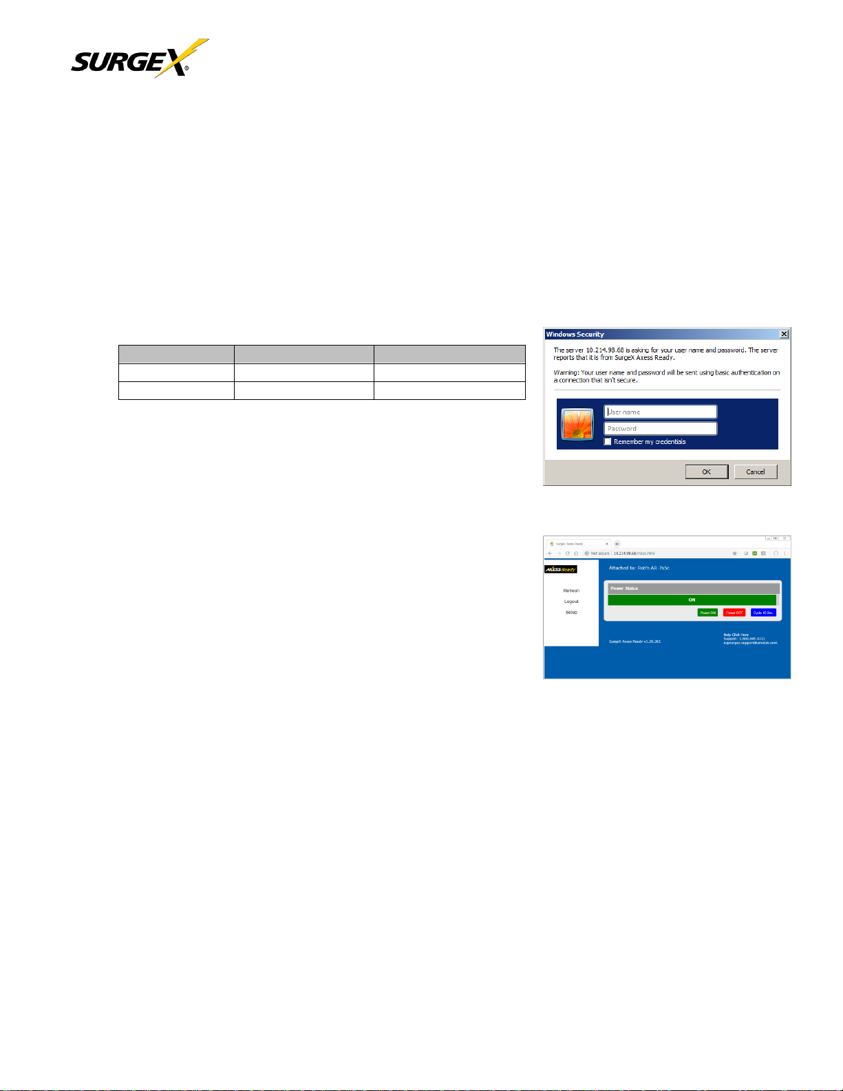
To access the web interface, open a web browser and enter the IP address of the AR into the address bar.
1. Password
The AR uses two username/password credential sets, one for normal power control (user)
and one that also provides access to the Setup functions (admin). Default
credentials:
Enter a valid username and password when prompted. When the proper
username/password combination is received, the Control and Status Page is
displayed.
2. Control and Status Page
Once a user is validated, the Control and Status page is displayed.
Note: Only one user may be logged in to the AR at a time.
Press “Power On”or “Power Off”to turn the AC output On or Off. In the event
of a power outage, the AC output will return to its last known
state prior to the outage.
Press “Cycle Power” to temporarily change the state of the
AC output for a specified cycle time (factory default is 10
seconds). The cycle operation performed will either be On-Off-On or Off-On-
Off, depending on the initial state of the AC output. During the power cycle operation, the Power Status bar will
indicate the temporary status with a Blue background. Once the cycle is complete, the
status bar will revert to its original condition. To abort a power cycle, press either “Power On”
or “Power Off” and the outlets will assume that status.
Use the Refresh button to update the page with the most current status. Use of the browser’s refresh button
may lead to inadvertent power switching. If an NTP time server is being used, the time of the last refresh will be
displayed in the upper right corner, as well as History log below the Power Status

© 2019 AMETEK Electronic Systems Protection | Technical Support: 800-645-9721 | surgex.com
8
SA-82-AR User Manual
_________________________________________________________________________________________
3. Setup Pages
Setup pages are only available while logged in with Administrator credentials. Press Save to save the new settings.
If the new settings require the AR to be rebooted, a Reboot button will appear at the bottom of the page. Settings
requiring reboot will not take effect until the unit is rebooted.
Device
Location ID: Specifies a name label (up to 20 characters) that will be displayed at the top of all pages.
Assigning unique names is helpful for management of multiple units.
Cycle Time: Specifies the length in seconds of a power cycle (1-999 seconds). This is the amount of time
the outlet will temporarily be On or Off, depending on the initial outlet state.
Disable Off: When checked, removes the Power OFF button from the Status and Control page.
Initial State: Specifies the initial state the AC outlet(s) will assume when the unit is powered up or reset.
Upgrade Enable: Enables the ability to upgrade the firmware of the AR.
Auto Logout: Specifies the inactivity timer duration in minutes (0-99 minutes). If there is no activity after the
specified amount of time, the user will be automatically logged out. Setting the timer duration to 0 disables the
timeout feature.
Enable Security Timeout: When unchecked, disables the 2 minute window for setting IP address and factory
defaults via DMU.
Important: As the AR allows only one web user logged in at any time, use caution when
disabling the timeout feature, as it is possible to lock out other users by forgetting to log
out. Closing the web browser will not log the user out, and may lock out web access. In this
situation it will be necessary to access the AR via telnet and reboot the unit.

© 2019 AMETEK Electronic Systems Protection | Technical Support: 800-645-9721 | surgex.com
9
SA-82-AR User Manual
_________________________________________________________________________________________
Network
IP Mode: Select Static to manually set the IP address using the fields below, or choose
DHCP to allow the AR to automatically acquire its network settings from a DHCP server.
IP Address: Enter a static IP address in dotted decimal format. This field will be automatically set if using
DHCP.
Subnet Mask: Enter the Subnet Mask in dotted decimal format. This field will be automatically set if using
DHCP.
Gateway: Enter the Gateway in dotted decimal format. This field will be automatically set if using DHCP.
DNS: Enter the Domain Name Server address. This will be automatically set if using DHCP.

© 2019 AMETEK Electronic Systems Protection | Technical Support: 800-645-9721 | surgex.com
10
SA-82-AR User Manual
_________________________________________________________________________________________
Advanced Network
HTTP Port: Specify the port the web server will be accessed on. If the port is changed from the default
value of 80, the AR may be accessed by specifying the new port number in this format:
http://IPADDRESS:NEWPORT. Example: Navigate to http://192.168.1.254:8000 for an IP address of
192.168.1.254 on port 8000.
Linkback URL: This setting allows control of the hotlink displayed on the Goodbye page. It allows use of the
public IP address or DNS name instead of the internal IP address of the AR, which is the default setting. If this
setting is left blank, the hotlink will be the IP address of the unit. Enter up to 128 characters.
Telnet Port: Specify the port to use for telnet access (default 23).
DxP Port: Specify the port to use for DxP protocol (default 9100).
Time Setup: Setup of the time server is required for Scheduling and Logging
functions.
Enable: Enable or disable the use of the time server.
Time Server: Specify the time server. The default is time.nist.gov.
Time Zone: Specify the time zone (-12 to +12) relative to GMT.
DST Enable: Enable or disable the use of Daylight Savings Time.
DST Start/Stop: Specify the start and stop times for DST.

© 2019 AMETEK Electronic Systems Protection | Technical Support: 800-645-9721 | surgex.com
11
SA-82-AR User Manual
_________________________________________________________________________________________
AutoPing
The AutoPing feature allows the AR to automatically detect failed equipment and perform a timed
reboot or other power control function (like turning on an indicator or siren). First specify one or two IP
addresses to be periodically pinged. When the AR no longer receives a response from these addresses, the
programmed power control function is actuated. AND or OR logic can be applied to the two addresses, so
that both (AND) or either (OR) must fail in order to trigger the selected action.
Examples:
Server monitor: AR is installed with the device it
monitors and automatically reboots if there is no
response. Ideal for Kiosks and Servers.
Service monitor: AR is installed with the device to be
rebooted, but pings a remote host to test the
communication channel. Ideal for DSL/Cable Modem
verification.
AR monitors a network device, and powers up an alarm
or redundant system when there is no response. Ideal for
Hot Standby Servers, Environmental Control, Alert for
any network failure.
•
IP Address 1 and 2: Enter the IP
address(es) of the device(s) to be pinged.
•
Frequency 1 and 2: Enter the desired ping frequency in seconds for the device(s) to be pinged (1-
999 seconds).
•
Fail Count 1 and 2: Enter the number of times the ping must consecutively fail
(1-999) before the selected action is triggered.
•
Mode: Select the logic to be used (AND, OR, or Single). With AND logic, both AutoPings must
exceed their fail count to trigger the action. With OR logic, the action will be triggered if either
AutoPing exceeds its fail count. With Single, only AutoPing 1 is used.

© 2019 AMETEK Electronic Systems Protection | Technical Support: 800-645-9721 | surgex.com
12
SA-82-AR User Manual
_________________________________________________________________________________________
•
Action: Select the action to be triggered.
None
AutoPing not used
Power On –Latch
Upon triggering, AR will power on and remain so until
changed via web, telnet, or DxP.
Power On –Follow
Upon triggering, AR will power on. When the ping
response returns, AR will power off.
Power Off –Latch
Upon triggering, AR will power off and remain so until
changed via web, telnet, or DxP.
Power Off –Follow
Upon triggering, AR will power off. When the ping
response returns, AR will power on.
Power Cycle
Upon triggering, AR will cycle the power. AR will then
wait for (Ping Frequency x Fail Count) seconds; if the response does
not return, the power will be cycled again. This will repeatedly
continue until the ping response returns or AutoPing is turned off.
Ensure that the AutoPing frequency is longer than the time
required to reboot the device.
Power Cycle - Once
Upon triggering, AR will cycle power one time. It will not cycle again
automatically until the ping response returns and is lost again.
•
Restart: This setting delays the restart of the AutoPing tests after the Action is completed. This
setting allows time for the boot sequence of the failed device to complete.

© 2019 AMETEK Electronic Systems Protection | Technical Support: 800-645-9721 | surgex.com
13
SA-82-AR User Manual
_________________________________________________________________________________________
Schedule
The AR can schedule up to 8 recurring power events. For each event, you may define the starting date
and time, the action to be taken, and the repetition interval (optional).
Important: A Network Time Server (NTS) must be specified and enabled in order to use the time
scheduling feature. A list of public time servers is available at http://www.ntp.org.
•
Date: Set the initial date for the event in mm/dd/yyyy format.
•
Time: Set the initial time for the event in hh:mm format. Hours are specified in
24 hour format; for example, 8:05 pm would be entered as 20:05.
•
Repeat (Optional): Set the repetition interval. 0-999 Days, Hours, or Minutes.
•
Action: Set the action to be scheduled. On, Off, or Cycle.
•
Enable: Enables the event when checked. Uncheck to disable the event.
•
Clear: Deletes a schedule.

© 2019 AMETEK Electronic Systems Protection | Technical Support: 800-645-9721 | surgex.com
14
SA-82-AR User Manual
_________________________________________________________________________________________
Role
Username (fixed)
Password (user set)
Administrator
admin
admin
User
user
user
Passwords
Two passwords are used by the AR. The User password allows control of the AC output state, but provides
no access to Setup functions. The Administrator password allows full control and setup of the AR.
Passwords may be up to 20 characters long and are case sensitive.
The AR supports three modes of user and password operation.
•
Login Required: Login with password is required for web and telnet access.
•
Auto Login: No login challenge will be required for any mode of operation, until a
Setup function is requested.
•
User Disabled: There is no User account. The Admin username and password will
be required for operation and setup functions across all modes of operation. This is
the factory default mode.
•
Old Password: Enter the password currently in use.
•
New Password: Enter the new password to be used.
•
Confirm Password: Enter the new password to be used again.
Default credentials:

SA-82-AR User Manual
________________________________________________________________________________________________________________________
VI. Command Line Interface (CLI) Protocol
The Command Line Interface provides complete setup of all functions of the AR. The CLI may be accessed through the Telnet protocol, and requires a Telnet
client program. Some commands of the CLI require administrative rights; these are indicated in the following tables.
Notes:
•Telnet negotiations require sending these bytes when first connecting: (0x) FF FD 01 FF FD 03 FF FB 1F FF FB 18 FF FB 20
•Every command must be followed by a Carriage Return and Line Feed: (0x) 0D 0A
1. Prompts
Prompt
Description
User>
Prompts the user to enter the user name (either user or admin).
Password>
Prompts the user to enter the password.
Axess Ready>
Prompt displayed while logged in.
Axess Ready Reboot Required>
Prompt displayed after changes have been made that require a reboot. This
prompt will remain active until the AR has been rebooted.
2. Control Commands
Command
Description
Admin
Fact Def
get outlet
Returns the current status of the outlet.
No
set outlet < on | off | cycle >
Sets the outlet to the selected state.
No
3. Device Commands
Command
Description
Admin
Fact Def
get location
Returns the location ID.
Yes
Axess
Ready
set location < 20 character max >
Sets the location ID.
Yes
get cycle
Returns the cycle time currently in use in seconds.
Yes
10
set cycle < 1-999 >
Sets the cycle time in seconds.
Yes
get upgrade enable
Returns the upgrade enable status.
No
Disabled
set upgrade enable < yes | no >
Enables or disables the ability to upload new
firmware.
Yes
Login
Prompts for admin credentials when logged in as user.
No
Logout
Terminates the telnet session.
No
Reboot
Reboots the AR.
Yes
© AMETEK Electronic Systems Protection, Inc. | Technical Support: 800-645-9721 | surgex.com 15

© AMETEK Electronic Systems Protection, Inc. | Technical Support: 800-645-9721 | surgex.com
16
SA-82-AR User Manual
_________________________________________________________________________________________________________________________
4. Network Commands
Command
Description
Admin
Fact Def
get network
Returns all network settings currently in use. Example: Mode:
DHCP
IP Address: 10.1.2.69
Subnet: 255.255.255.0
Gateway: 10.1.2.1
HTTP Port: 80
Telnet Port: 23
DxP Port: 9100
Timeout: 20
Yes
set ipmode < static | dhcp >
Sets the IP address mode. Static mode locks the IP address as
set; DHCP mode allows a DHCP server to assign the address.
Yes
DHCP
set ipaddress < dotted decimal >
Sets the IP address.
Yes
DHCP
set subnet < dotted decimal >
Sets the Subnet Mask.
Yes
DHCP
set gateway < dotted decimal >
Sets the Gateway address.
Yes
DHCP
set http port < 0-65535 >
Sets the port that the internal Web server listens for incoming
connections on. When set to 0 the web server is disabled. May not be
disabled when Telnet and DxP are both disabled.
Yes
80
set telnet port < 0-65535 >
Sets the port that the internal Telnet server listens for incoming
connections on. When set to 0 the Telnet server is disabled. May not
be disabled when Web and DxP are both disabled.
Yes
23
set dxp port < 0-65535 >
Sets the port that the internal DxP service listens for incoming
connections on. When set to 0 the DxP service is disabled. May not
be disabled when Web and Telnet are both disabled.
Yes
9100
Set linkback <url>
This command sets the linkback URL displayed on the logout page.
Yes
set timeout < 0-999 >
Sets the automatic network timeout in minutes.
Yes
2

© AMETEK Electronic Systems Protection, Inc. | Technical Support: 800-645-9721 | surgex.com
17
SA-82-AR User Manual
_________________________________________________________________________________________________________________________
5. AutoPing Commands
Command
Description
Admin
Fact Def
get autoping
Returns all AutoPing settings currently in use. Example: AutoPing 1
AutoPing 2
IP Address: 10.1.2.36 0.0.0.0
Frequency: 60 10
Fail Count: 3 3
Status: OK OK
Trigger Count: 0 0
--------------------------------------
Mode: Single Action:
On-Latch
Yes
set autoping < 1 | 2 > address < dotted decimal >
Sets the IP address to be pinged for AutoPing 1 or 2.
Yes
0.0.0.0
set autoping < 1 | 2 > frequency < 1-999 >
Sets the frequency (how often the ping is sent) for
AutoPing 1 or 2 in seconds.
Yes
10
set autoping < 1 | 2 > failcount < 1-999 >
Sets the number of consecutive failures the AutoPings must detect
before the AutoPing considers the pinged device to be failed.
Yes
3
set autoping mode < single | and | or >
Sets single AutoPing (AutoPing 1) or two AutoPing relationship
AND or OR.
Yes
AND
set autoping action < none | on-latch | on-follow | off-latch |
off-follow | cycle | cycle-once >
Sets the action to be performed when the AutoPing is triggered.
Yes
None
set autoping cycle <0-999>
Sets the maximum number of power cycles when the AutoPing
triggers. 0 = Unlimited
Yes
1
set autoping restart <1-999>
Sets the delay in seconds to restart AutoPing tests after Action.
Yes
0
6. User Commands
Command
Description
Admin
Fact Def
set password < user | admin > < old > < new > < repeat >
Sets the password of the User or Administrator.
Yes
user | admin
set user account <yes | no>
Sets whether or not a user account is used.
Yes
No
set login required <yes | no>
Sets whether or not a login is required for user level operation. A login
is always required for admin functions.
Yes
Yes

© AMETEK Electronic Systems Protection, Inc. | Technical Support: 800-645-9721 | surgex.com
18
SA-82-AR User Manual
_________________________________________________________________________________________________________________________
7. Event Commands
Command
Description
Admin
Fact Def
get events
Returns all scheduled events currently in use. Example:
Date Time Repeats Action
1. 12/22/2011 14:00 every 2 Hour(s) Cycle
2. every 0 Day(s) On
3. every 0 Day(s) On
4. every 0 Day(s) On
5. every 0 Day(s) On
6. every 0 Day(s) On
7. every 0 Day(s) On
8. every 0 Day(s) On
No
get time
Returns the current time and time server. Example:
Current Time: 10:14:17 12/20/2011
Server: 10.1.2.12
No
set time server < dotted decimal >
Sets the IP address of a Network Time Server.
Yes
64.90.182.55
set time enable < yes | no >
Enables or disables the use of a time server and scheduled events.
Yes
No
set event <1-8> <run | hold>
Allow the event to run, or put the event on hold.
Yes
Run
set event < 1-8 > date < mm/dd/yyyy >
Sets the scheduled event’s starting date.
Yes
set event < 1-8 > time < hh:mm:ss >
Sets the time the scheduled event will occur in 24-hour format.
Yes
set event < 1-8 > repeat < day | hour |
minute >
Sets the repetition interval type for the selected event.
Yes
set event < 1-8 > mult < 0-999 >
Sets the number of repetition intervals for the selected event. For example,
20 days, 30 minutes, 24 hours, etc.
Yes
set event < 1-8 > action < on | off | cycle >
Sets the action to be performed at the scheduled time.
Yes
del event < 1-8 >
Deletes the scheduled event.
Yes

© AMETEK Electronic Systems Protection, Inc. | Technical Support: 800-645-9721 | surgex.com
19
SA-82-AR User Manual
________________________________________________________________________________________________
VII. DxP Protocol
1. Overview
The DxP Protocol is a packet-based protocol designed to be extensible. This protocol is transmitted over TCP
on a user-defined port. The factory default DxP port is 9100.
The protocol uses a Hello handshake to establish unique sequence numbers to allow for advanced security when
AES encryption is used. With AES enabled, all messages must be encrypted with the AES Passphrase set in the
device.
After the Hello, a Command and Response sequence follows. Any number of
Command → Response sequences are permitted after Hello.
2. Hello Handshake
The client sends a Hello message in the form of a text string ‘hello-000’. The DxP enabled device will
respond with a packet containing the unsigned 16 bit sequence number. This sequence number is incremented
by the client and server with each correct packet sent.
Example:
Client
Server
hello-000
→
←
1234
(seq 1234)
Command
(seq 1235)
→
←
Response
Command
(seq 1237)
→
←
Response
Table of contents
Other Ametek Surge Protector manuals
Popular Surge Protector manuals by other brands

Radio Shack
Radio Shack 61-2420 owner's manual

M-system
M-system MDCAT-A Series instruction manual

Mersen
Mersen Surge-Trap ST-50 Series installation instructions

EFI
EFI TITAN Omni-Phase OSW Instruction bulletin

Emerson
Emerson SOLAHD STCPOE65FF quick start guide

Kensington
Kensington SmartSockets K62144NA manual

Tripp Lite
Tripp Lite TLP76MSG Specifications

Belkin
Belkin BV101 Series Basic installation instructions

Panamax
Panamax M4315-PRO quick start guide

MCG Surge Protection
MCG Surge Protection XT Series installation instructions

CPT
CPT PSM2 Series installation instructions

Intermatic
Intermatic AG3000 Installation instruction