AMG 9WT User manual

9WT
Anleitung / Manual
Analog Manufaktur Germany

Lieber Musikliebhaber, wir
freuen uns sehr, dass Sie sich für
unseren Tonarm 9WT entschieden
haben!
Dear music-lover, we greatly
appreciate your choice for our
9WT tonearm!
1
DE:
EN:

Table of Content
Important information
Unpacking
Parts List
Functional description
Assembly
Technical data
Quality inspection
Warranty
Contact information
Inhaltsverzeichnis
Wichtige Hinweise
Auspacken
Lieferumfang
Beschreibung der Funktionen
Aufbau
Technische Daten
Qualitätsprüfung
Gewährleistung
Kontaktinformationen
Inhaltsverzeichnis / Table of content
2
....................................3
................................................4
.............................................5
.................6
.......................................................7
..................................19
....................................20
......................................21
............................22
.............................3
.................................................4
......................................................5
.............................6
....................................................7
.......................................19
..................................20
..................................................21
..............................22

DE: Warnung !
Seien Sie während des Auspackens, im Aufbau und während des Gebrauchs
sehrvorsichtig,daimTonarmsehrligraneElementeverbautsind.
Bitte achten Sie darauf, dass Sie alle Schrauben an diesem Präzisionsprodukt
mit einem geringen Drehmoment und mit Fingerspitzengefühl anziehen.
Verwenden Sie den Tonarm nicht weiter als 10 m vom Verstärker entfernt.
Nur in trockenen Räumen verwenden.
Nur zum Abspielen von Schallplatten verwenden.
EN: Warning !
Please take care during unpacking your tonearm for setup and during use to
avoid damage of delicate tonearm elements.
Please be advised to tighten all screws at this precision engineered product at
low torque and by a sensitive tough.
Donotusethetonearmmorethan10mawayfromtheamplier.
Use only in a dry environment.
Use only for playing records.
Wichtige Hinweise / Important information
3

DE: Bereiten Sie einen weichen Untergrund (z. B. Decke) auf einem Tisch vor.
Öffnen Sie die Holzbox und entnehmen Sie den Schaumstreifen oberhalb des
Tonarms.
Entnehmen Sie zuerst die Teile 2 - 11 (siehe S. 5) und legen diese auf die
vorbereitete weiche Unterlage. Entnehmen Sie zuletzt den Tonarm und legen
ihn auch auf die vorbereitete, weiche Unterlage.
Anschließend, legen Sie den Schaumstreifen wieder in die Holzbox und lagern
Sie diese an einem trockenen Ort. Die Box bitte nicht entsorgen, falls Sie diese
noch einmal benötigen sollten.
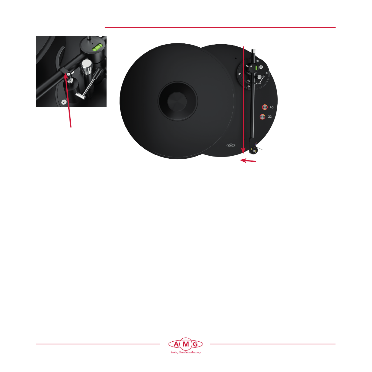
EN: Prepare a soft surface (e. g. blanket) on a table. Open the wooden box and
remove the foam block protecting the shaft of the tonearm.
Remove all accessories and tools and place them on the
prepared soft surface. Next, remove the tonearm and place it on
the prepared soft surface.
When all contents have been removed, put the foam strip back into the
wooden box and store it in a dry place. The box may be needed again, so
please do not dispose of it.
Auspacken / Unpacking
4

Parts List 9WT
1 - 1 x tonearm type 9WT
2 - 1 x main counterweight (two-piece)
3 - 1 x auxilliary counterweight ring (small)
4 - 1 x Tracking force scale
5 - 1 x Alignment gauge with locator pin
6 - 1 x Allen key 1.5 mm
7 - 1 x Allen key 2.0 mm
8 - 1 x Set screw M3 x 4 mm
9 - 1 x auxiliary oval-head headshell
- crew M3 x 4 mm
10 - 1 x Plastic washer
11 - 1 x Mounting collar and
- hardware (optional)
Lieferumfang 9WT
1 - 1 x Tonarm Typ 9WT
2 - 1 x Gegengewicht (zweiteilig)
3 - 1 x Gegengewicht Ring klein
4 - 1 x Waage
5 - 1 x Einstellschablone mit Zylinderstift
6 - 1 x Sechskantschlüssel 1,5 mm
7 - 1 x Sechskantschlüssel 2,0 mm
8 - 1 x Gewindestift M3 x 4 mm
9 - 1 x Linsenkopfschraube
- M3 x 4 mm
10 - 1 x Unterlegscheibe Kunststoff
11 - 1 x Adapterplatte mit Befesti-
- gungsschrauben (optional)
Lieferumfang / Parts List
5
1
11 8
9
10
7 65
4
3
2
2

9WT Adjustment elements
1 - Rest clip
2 - Bubble Level
3 - Counterweight main ring
4 - Counterweight additional ring
5 - VTA locking knob
6 - Anti-skating adjustment knob
7 - VTA height adjustment knob
8 - Azimuth adjustment screw
9 - Azimuth locking screw
10 - Cueing device locking screw
9WT Einstellelemente
1 - Tonarm Klemmung
2 - Libelle
3 - Gegengewicht Grundkörper
4 - Gegengewicht Zusatzring
5 - VTA Klemmschraube
6 - Anti-Skating Einstellschraube
7 - VTA-Höheneinstellschraube
8 - Azimut Einstellschraube
9 - Azimut Klemmschraube
10 - Tonarmlift Klemmschraube
Beschreibung / Description
6
6
10
9
8
7
5
43
2
1

DE: Drehen Sie die VTA-Höheneinstellschraube im Uhrzeigersinn, bis der Pin der
VTA-Höheneinstellschraube ein paar Millimeter unten herausschaut. Führen Sie
das Phonokabel von unten durch Chassis und Tonarmbasis.
Verbinden Sie den Tonarm mit dem 5-poligen Phonostecker. Achten Sie auf
die Ausrichtung des Steckers.
EN: Turn the VTA height adjustment screw clockwise until the pin of the VTA height
adjustment screw comes out a few millimeters at the bottom. Feed the phono
cable through the chassis and tonearm base from below.
Connect the tonearm to the 5-pin phono plug, paying careful attention to
the orientation of the connecting pins to avoid damage.
Schritt 1 / Step 1
7
DE: Tonarmbasis
EN: Tonearm base

DE: 1) Drehen Sie die VTA Klemmschraube (1) gegen den Uhrzeigersinn ein
wenig heraus und drücken Sie die Verriegelung (2) nach innen, nur so
können Sie den Tonarm in die Tonarmbasis stecken.
2) Stecken Sie den Tonarm, wie in Bild A abgebildet, in die Bohrung der
Tonarmbasis bis der Pin der Höheneinstellung Kontakt zur Basis hat und ziehen
Sie die VTA Klemmschraube (1) wieder handfest an.
EN: 1) Turn the VTA locking knob (1) counterclockwise and gently press the VTA
locking pin (2) to ensure it is not protruding out and that the arm can freely
slide into its base.
2) Insert the tonearm into the hole of the tonearm base as shown in picture A,
into the hole of the Tone arm base until the pin of the height adjustment is in
contact with the base and turn the VTA locking knob (1) clockwise to lock the
arm in place. Do not over-tighten.
Schritt 2 / Step 2
8
2
1
A
1

DE: Klemmen Sie den Arm an seiner Ruheposition fest (Bild A).
Öffnen Sie leicht die VTA Klemmschraube von Schritt 2 und richten Sie den
Tonarm so aus, dass der Arm direkt nach vorne zeigt. Ziehen Sie die
Rändelschraube wieder handfest an. Diese Positionierung ist für das
Anti-Skating wichtig.
EN: Place the arm tube securely into the rest clip (Picture A).
Slightly loosen the VTA locking knob from step 2 and align the tonearm to point
forward, with the headshell oriented between the control buttons and the
AMG logo. Tighten the VTA locking knob again to lock the position. This
positioning is important for anti-skating and can be adjusted again later
if necessary.
Schritt 3 / Step 3
9
DE: Tonarm in
geklemmter
Ruheposition
EN: Tonearm in
clamped rest
position
A
DE: Ausrichtung
des Tonarms
EN: Alignment of
the tonearm

DE: Nehmen Sie das Gegengewicht und schieben Sie es, wie abgebildet,
vorsichtig auf das hintere Ende des Armrohrs. Halten sie mit der
anderen Hand das Tonarmrohr fest und achten Sie darauf, dass Sie die zwei
Federstifte nicht verbiegen. Dies geht einfacher, wenn Sie dabei das Gewicht
leicht drehen.
EN: Take the counterweight and carefully push the counterweight onto the rear
end of the arm tube as shown. Hold the tone arm tube with the other hand
and make sure that you do not bend the two spring pins. This is easier if you
turn the weight slightly.
Schritt 4 / Step 4
10
DE: Federstift des patentierten Lagers
EN: Spring pin of the patented bearing

DE: Entfernen Sie die Adapterplatte, indem Sie die Adapterschraube lösen.
Beachten Sie beim Anbau Ihres Tonabnehmers, dass die beiden Höcker nach
oben zeigen müssen.
Legen Sie die Adapterplatte auf die Oberseite Ihres Tonabnehmers und
schrauben Sie diesen mit den Tonabnehmerschrauben fest.
EN: Remove the cartridge mounting plate by loosening the thumb screw on
the headshell. When mounting your cartridge to the plate, make sure that the
two bumps on the plate point upwards.
Screw your cartridge into the plate using the mounting hardware provided by
your cartridge manufacturer.
Schritt 5 / Step 5
11
DE: Tonabnehmer Schrauben
EN: Cartridge scews
DE: Adapterschraube
EN: Thumb screw
DE: Adapterplatte Tonabnehmer
EN: Cartridge mounting plate
DE: Adapterschraube
EN: Thumb screw

12
Schritt 6 / Step 6
DE: 1) Schrauben Sie die Adapterplatte mit dem Tonabnehmer wie abgebildet
1) wieder an das Headshell, Sie können zusätzlich die Kunststoffscheibe unter
1) die Adapterschraube legen.
2) Verbinden Sie äußerst vorsichtig die Tonarmkabel mit den Steckern am
2) Tonabnehmer und beachten Sie dabei die korrekte farbliche Zuordnung. Im
2) Zweifelsfall die Anleitung des Tonabnehmers beachten.
EN: 1) Screw the cartridge mounting plate with cartridge attached back onto the
1) headshell as shown. If you wish, you can place the plastic washer between
1) the headshell and the thumb screw to prevent scratches.
2) Connect the lead wires very carefully to the posts on the back of your
2) cartridge, observing the correct colour assignment. In case of doubt, follow
2) the instructions provided by your cartridge manufacturer.
DE: Adapterschraube
EN: Thumb screw
DE: Bei Bedarf Kunststoffscheibe unterlegen
EN: If necessary, place the plastic
washer underneath
DE: Headshell
EN: Headshell

13
Schritt 7-A / Step-7-A
DE: 1) Öffnen Sie das Batteriefach der Waage und legen die Batterien
1) (Typ AAA) korrekt ein.
2) Stecken Sie den Zylinderstift (A) durch die Bohrung im Headshell.
3) Legen Sie die Waage wie abgebildet auf den Plattenteller und stellen Sie
1) dasAuagegewichtdenAngabeninderTonabnehmerbeschreibung
1) entsprechend ein. Dies ist nur eine vorübergehende Einstellung
1) desAuagegewichtes.BittebeachtenSiegleichzeitigPunkt4.
EN: 1) Open the battery compartment of the tracking force scale and insert the
1) provided AAA batteries.
2) Insert the alignment gauge locator pin (A) through the hole in the side of
1) the headshell.
3) Place the scale on the turntable as shown and set the tracking force
1) according your cartridge manufacturers instructions. This is a
1) temporary tracking force setting and will change later. Note point 4.
A

14
Schritt 7-B / Step-7-B
DE: Lösen Sie die VTA Klemmschraube an der Rückseite des Tonarms und
verwenden Sie die VTA-Höheneinstellschraube, um die Höhe des Tonarms
einzustellen. Überprüfen Sie die richtige Höhe mit der eingebauten Libelle. Die
Libelle sollte zentriert sein, wenn Sie die Nadel auf die Waage oder eine
Schallplatte gelegt haben. Ziehen Sie nach der Überprüfung die
VTA-Klemmschraube wieder an und stellen Sie sicher, dass der Arm immer
nochnachvornezeigt(sieheSchritt3).PrüfenSiedieAuagekrafterneut
(Schritt 7) und justieren das Gegengewicht falls erforderlich.
EN: Loosen the VTA locking knob at the back of the arm, then use the VTA height
adjustmentknobtosetthetonearmheight.Conrmtheproperheightwiththe
built in bubble level. The bubble should be centered when your stylus is placed
onthetrackingforcegauge,orarecord.Afterconrming,tightentheVTA
locking knob again, ensuring the arm is still pointing forward (see step 3). Also
check the tracking force again (step 7) and adjust the counterweight
if necessary.
DE: VTA-Höheneinstellschraube
EN: Adjustment knurled screw
for height adjustment
DE: 4) Gleichzeitig sollte die
1) Tonarmhöhe (VTA) so
1) eingestellt werden, dass das
1) Tonarmrohr waagrecht ist.
EN: 4) At the same time, the tone arm
4) height (VTA) should be
4) adjusted to a horizontal
4) position of the arm tube.

15
Schritt 8 / Step 8
DE: 1) Legen Sie die Einstellschablone (A) wie abgebildet auf den Plattenteller
1) und setzten sie den Tonarm so auf die Einstellschablone, dass der
1) Zylinderstift in die Nut der Schablone gleiten kann.
2) Richten Sie den Tonabnehmer so aus, dass die Nadel exakt über der
2) Markierung (B) positioniert ist und ziehen Sie alle Schrauben wieder fest.
EN: 1) Place the alignment gauge (A) on the platter and lower the headshell
1) onto the gauge so that the locator pin in the headshell slides into the gap
1) on the gauge, as shown in the picture.
2) Adjust the cartridge alignment using the cartridge mounting plate and
2) thumb screw so that the needle is positioned exactly above the mark (B) on
2) the gauge, then re-tighten all screws.
A
B

16
Schritt 9 / Step 9
DE: 1) Entfernen Sie den Zylinderstift (A) und die Einstellschablone.
2) Legen Sie die Waage erneut wie abgebildet auf den Plattenteller und
2) stellenSiedasGegengewichtnalsoein,dassdasAuagegewichtder
2) Nadel den Angaben in der Tonabnehmerbeschreibung entspricht.
EN: 1) Remove the locator pin (A) from the headshell.
2)Placethetrackingforcescaleagainontheturntableasshownandnally
2) setthecounterweightforthenaltrackingforce,followingcartridge
2) manufacturer‘s instructions.
A

17
Schritt 10 / Step 10
DE: Azimut-Einstellung: Die Azimut Einstellung wird benötigt, um schräg stehende
Nadeln lotrecht zur Schallplatte auszurichten. Für die Azimut Einstellung
benötigen Sie geeignetes Einstellwerkzeug oder Sie fragen Ihren
Fachhändler.
Lösen Sie die Fixierschraube (1), mit der Einstellschraube (2) wird das Azimut
angepasst. Danach muss die Fixierschraube (1) wieder angezogen werden.
EN: Azimuth adjustment: Azimuth adjustment is an optional adjustment that can
be made to optimize channel performance in certain cartridges. It is only
recommended for experienced users or with direct dealer support.
Loosen the azimuth locking screw (1) before adjusting the azimuth adjustment
screw. Important! Handle the arm gently when the azimuth is unlocked, and
do not place the arm into its rest clip or serious damage can occur.
2. After adjusting to the desired azimuth, be sure to tighten the azimuth locking
screw (1) before using the tonearm to avoid serious bearing damage.
2
1

18
Schritt 11 / Step 11
DE: AntiSkating:DasmagnetischeAntiSkatingwirktgegendieRotationsiehkräfte
während der Drehbewegung der Schallplatte.
- Wenn Sie die Einstellschraube des Anti Skatings im Uhrzeigersinn drehen,
- erhöht sich die Zugkraft in Richtung nach außen.
- Wenn Sie die Einstellschraube des Anti Skatings gegen den Uhrzeigersinn
- drehen, verringert sich die Zugkraft in Richtung nach Außen.
EN: Anti Skating: The magnetic anti skating works against the rotational centrifugal
forces during the rotation of the record.
- If you turn the antiskating adjustment screw clockwise, the lateral force
- increases in the outward direction (stronger antiskate).
- If you turn the antiskating adjustment screw counter-clockwise, the lateral
- force decreases in the outward direction (weaker antiskate).
DE: Einstell-Rändelschraube
für Anti Skating
EN: Adjustment knurled screw
for Anti Skating

19
Technische Daten / Technical data
DE: Tonarm Typ 9WT
EFFEKTIVE LÄNGE: 229,0 mm
EFFEKTIVE MASSE: 10,2 g
ABSTAND DREHPUNKT ZU MITTE TELLERACHSE: 211,0 mm
ÜBERHANG: 18,1 mm
VERSATZWINKEL: 24,07 °
INNERER NULLPUNKT: 66,0 mm
ÄUSSERER NULLPUNKT: 120,9 mm
BOHRUNGSGRÖSSEN d. MOTAGEBUCHSEN: 20, 25 od. 30 mm
BOHRUNGS-LOCHKREIS DURCHMESSER: 30, 48 mm
EN: Tonearm Type 9WT
EFFECTIVE LENGTH: 229,0 mm
EFFECTIVE MASS: 10,2 g
DISTANCE FROM PIVOT TO PLATTER CENTRE: 211,0 mm
OVERHANG: 18,1 mm
OFFSET ANGLE: 24,07 °
INNER NULL POINT: 66,0 mm
OUTER NULL POINT : 120,9 mm
BORE SIZE FOR MOUNTING BUSHING: 20, 25 or 30 mm
SCREW HOLE CIRCLE: 30, 48 mm
Table of contents
Popular Accessories manuals by other brands

ORION TELESCOPES & BINOCULARS
ORION TELESCOPES & BINOCULARS 5567 quick start guide

fontastic
fontastic FontaHome quick guide

HomeMatic
HomeMatic HmIP-SPDR Mounting instruction and operating manual

Malmbergs
Malmbergs TM001-ZA instruction manual

Phcbi
Phcbi MCO-170AICD-PE operating instructions

Craftsman
Craftsman 358.792443 Operator's manual