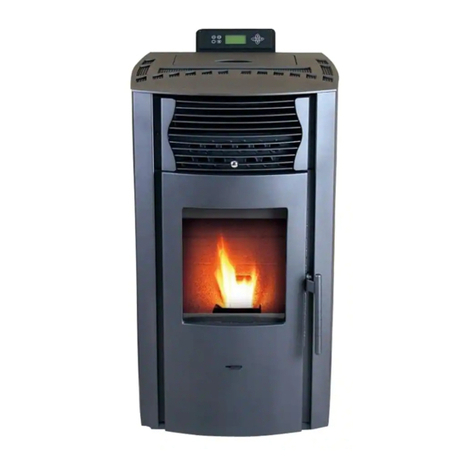
AMG INSERT 13 User manual

Carefully read t e precautions and follow t e procedures correctly.
WARNING!
Do not try to install the stove;
always contact authorized and trained personnel.
- In case of breakage or poor functioning always contact t e Aut orized Assistance Centre;
any attempt to remove parts or perform maintenance on the device can expose the user to electrical
shock danger. The stove contains parts whose maintenance must be done by the Authorized Assistance
Centre.
- T e stove is a eating device; its parts reach extreme temperatures and contact without adequate pro-
tection can provoke burns of various degrees.
Pay particular attention to children.
- In case of a transfer, contact t e Aut orized Assistance Centre for t e removal and new installation.
- Do not insert fingers or ot er objects in t e air flow exit slits.
Inside the device there is a high speed fan that could cause grave personal injury. Pay particular atten-
tion to children.
- Do not remain for long periods directly exposed to t e flow of ot air.
Direct and prolonged exposition to the cold air could be hazardous to health. Pay particular attention in
rooms where there are children, the elderly or the ill.
- In case t e stove functions poorly, s ut down t e device immediately, un ook t e appropriate
automatic switc and contact t e Aut orized Assistance Centre. The continued use of the device
in said conditions can cause fires or flashes.
WARNING!
- During t e stove installation operation, keep c ildren out of t e work area to avoid unforeseen acci-
dents.
- Do not block or cover in any way t e body of t e stove or obstruct t e slits placed on t e upper
side.
Obstructing said slits can cause fires.
- Do not use t e stove in areas containing precision devices or works of art.
The quality of the conserved objects may deteriorate.
- Do not expose animals or plants to direct air flow from t e unit.
Prolonged direct exposition to the flow of air from the stove can have negative effects on plants and ani-
mals.
- Occasionally ventilate t e room during t e use of t e device.
Insufficient ventilation can be the origin of insufficient oxygen in the room.
- Do not expose t e stove to contact wit water.
The electrical insulation could be damaged, with the consequent possibilities of electrocution and
breakage due to the thermal extremes.
- Verify t e installation conditions to locate eventual damage.
After the stove has completed 900 hours of operation (the lower screen will read “SErV”), contact the
Authorized Assistance Centre for cleaning and ordinary maintenance.
- Do not use inflammable gas near t e stove.
- Un ook t e automatic switc if t e device will not be used for long periods of time.
- We check the start up of all our stoves.

2
Nor s and confor ity declarations
Legislation
• Our company declares that the stove
conforms to the following norms for EC
European Directive marking.
• 89/336 EC and 2004/108 EC (EMC directi-
ve) and successive amendments.
• 2006/95 EC (low voltage directive) and suc-
cessive amendments.
• 2006/42 (machines directive).
• 89/106 EC (construction products).
•For installation in Italy refer to the UNI
10683/98 or su essive modifi ations; the
te hni ian installing the hydrothermal sani-
tary system will issue the de laration of
onformity a ording to L. 37/2008. The
installation of applian e has to be in a or-
dan e with lo al and national laws and with
European norms.
•EN 60335-1 - EN 50165 - EN 50366 - EN
55014-1 - EN 61000-3-2 - EN 61000-3-3 -
EN 14785.
Responsibility
The manufacturer declines every direct or
indirect, civil or penal responsibility due to:
• Poor maintenance.
• Failure to observe the instructions contai-
ned in the manuals.
• Use in non-conformity with the safety direc-
tives.
• Installation in non-conformity with the
norms in force in the country.
• Installation by unqualified or untrained per-
sonnel.
• Modifications and repairs not authorized by
the manufacturer.
• Use of non-original replacement parts.
• Exceptional events.
• Use of pellets not approved by the manu-
facturer.
Installazione
Flue
The flue must meet the following require-
ments:
• No other type of chimney, stove, boiler or
hood vent must be connected (Pict.1).
• It must be adequately distanced from com-
bustible or inflammable material by means
of an air cavity or opportune insulation.
• The internal section must be uniform, prefe-
rably circular: the square or rectangular
sections must have rounded corners with a
radius of no less than 20 mm, a maximum
relationship between the sides of 1.5; the
walls as smooth as possible with no nar-
rowed sections, regular curves and no
discontinuities, with deviations from the
axis not more than 45°.
NO NO YES
Pict.1: methods for installing the flue

3
Installation
GB
NO
YES
Pict. 2: characteristics of the chimney ca
• Every device must have its own flue with a
diameter equal to or larger than the stove’s
smoke clearing tube and a height not less
than that declared.
• Never use two stoves, a chimney and a
stove, a stove and a wood kitchen, etc in
the same environment, since the draught of
one could damage the draught of the other.
• Collective type ventilation ducts that can
lower the atmospheric pressure in the
installation environment are not permitted,
even if installed in environments that are
adjacent to and communicating with the
locale of the installation.
• It is forbidden to make fixed or mobile ope-
nings in the flue to connect devices diffe-
rent from that for which it is originally inten-
ded.
• It is forbidden to pass other air feeding
channels or tubes for electrical system
usage through the flue, even if oversized.
• It is advisable that the flue be furnished with
a chamber which collects solid material
and eventual condensation situated below
the vertical entrance to the flue so that it is
easily opened and inspected through the
air-tight door.
• Whenever flues with parallel exits are used
it is advisable to raise the upwind chamber
by one element.
• The chimney tube must never pass across a
combustible surface.
T e C imney Cap
The chimney cap must respect the following
requirements:
• It must have the equivalent diameter and
internal form of the flue.
• It must have a useful outlet diameter of not
less than double that of the flue.
• The chimney cap on the roof or that remains
in contact with the outside (for example, in
case of open lofts or attics), must be cove-
red with elements in brick or tile and must,
in any case, be well insulated.
• It must be constructed to prevent rain,
snow, and extraneous bodies from entering
the flue and so that the discharge of the
products of combustion is not inhibited by
wind from any quarter or strength (wind-
proof chimney cap).
• The chimney cap must be positioned in
such a way as to guarantee the adequate
dispersion and dilution of the products of
combustion and in any case, must be out
of the reflux zone. This zone has different
dimensions and forms according to the
angle of inclination of the roof so it is
necessary to adopt minimum heights
(Pict. 2).
• The chimney cap must be a wind-proof
type and must be above the ridge.
• Eventual structures or other obstacles
that are higher than the chimney cap
must not be too close to the chimney cap
itself.

4
Positioning
The adjacent locale must not be used as
a garage or be a space without ventila-
tion or air exchange, a storage area for
combustible material or used for an
activity that has a fire hazard.
S oke discharge
The discharge system must be for the stove
only (it is not permissible to discharge into flues
in common with other devices).
The smoke discharge takes place through the 8
cm diameter tube placed at the back (Pict. 3).
A “T” with a condensation collection cap
should be provided.
The smoke discharge of the stove must be
connected with the outside using a steel or
black tube (resistant up to 450°C) without
obstructions.
The tube must be hermetically sealed.
To make the tubes airtight and for their even-
tual insulation, it is necessary to use material
resistant up to at least 300°C (silicone or putty
for high temperatures).
The horizontal sections can be up to 2 m long.
It is possible to have up to three 90° curves.
If the discharge tube does not insert in the
flue, an opportunely fastened vertical section
of at least 1.5 m is necessary (except for evi-
dent safety contraindications) and a wind-
proof termination (Pict.3). The vertical duct
can be inside or outside. If the smoke duct is
outside it must be insulated (Pict.4).
If the smoke duct is inserted in a flue, this
must be certified for solid combustibles and if
it is larger than 150 mm in diameter, modifica-
tion is necessary by inserting a tube and seal-
ing the discharge with respect to the parts in
brickwork.
It must be possible to inspect all the sections
of the smoke duct. If it is a fixed duct it must
have openings for inspection and cleaning.
External air intake
The stove must be furnished with the air neces-
sary to guarantee the regular functioning of the
combustion and an environmental well being.
• Be sure that the room where the stove is
installed has sufficient aeration and, if
necessary, install an air intake duct with a
minimum recommended diameter of 50 mm
to bring in air from the outside.
• The external air intake must communicate
with the stove and positioned so that it is
not obstructed. It must be protected with a
permanent non-closable grill or other suita-
ble protection provided that the minimum
diameter is not reduced.
• The air flow can also be acquired from a
locale adjacent to where the stove is instal-
led as long as that flow can freely cross the
permanent non-closable openings that
communicate with the outside.
• The presence in the local adjacent to where
the stove is installed, of other devices in use
or of suction devices that cause a contrary
draught effect must not create a lower air
pressure in the locale than in the outside
environment.
• In the adjacent locale the permanent ope-
nings must respond to the requisites which
are listed in the points above.
530±10 mm. 689±10 mm.
590±10 mm.
Pict. 3 Sizing of the fire lace
80mm
ø 48/50 mm
190±10 mm.
The stove is furnished with an electrical cable
to connect to a 230V 50Hz socket, preferably
with a thermal-magnetic switch. Variations in
tension of more than 10% can compromise
the stove (if not already present, an adequate
differential switch should be provided).
The electrical system must comply with the
norms; verify in particular the efficiency of the
ground circuit. The electrical feed cable must
be of a diameter adequate to the power of the
device.
The stove must be completely level. Verify the
weight bearing capacity of the flooring.
The placement of the stove within the living
environment is determined so that the envi-
ronment is heated in a uniform manner.
Before deciding where to place the stove,
keep in mind that:
• The air used for combustion must not come
from a garage or a space without ventilation
or air exchange, but from a free space or
the outside.
• The stove should not be installed in a
bedroom.
• Rather it is preferable to install the stove in
a large, central room of the house to insure
the maximum heat circulation.
Pict. 4: minimum distance
• A grounded electrical connection is obliga-
tory (if the cable issued with the stove is not
long enough to reach the closet socket, use
an extension cable along the floor).
Fire safety distance
The stove must be installed respecting the
following safety conditions:
Keep an adequate clearance between the
stove and the walls, in order to grant a regu-
lar warmth flow. This clearance must exceed
10 mm on the sides of the stove and 15 mm
on the upper part (Pict. 4).
• Minimum distance from the sides and the
back must be 40 cm from moderately
inflammable material.
• Easily inflammable material must not be
place closer than 80 cm in front of the
stove.
• Do not place objects in inflammable mate-
rial or any material that can compromise
the operation of the stove on the stove or
within the safety distance.
• In addition, it is advisable to keep all ele-
ments of combustible or inflammable mate-
rial such as beams, wooden furniture, dra-
pes, inflammable liquids, etc. outside the
radiance area of the stove, and in any case
at least 1 m from the heating block).
• In case of connection to wooden walls or
other inflammable material, it is necessary
to insulate the smoke discharge tube with
ceramic fibre or another material with the
same characteristics.
5
Positioning
GB
15 mm
10 mm 10 mm

6
Installation
Please follow the following procedure in order
to install the fireplace insert:
• Connect the “T” pipe to the support of the
gauge (Pict. 5).
• Insert the fastening gauge (Pict. 6) on the
base of the chimney. Fasten it with four
screws and proper plugs. The base of the
chimney must be completely flat.
• Fasten the brackets to the wall behind the
chimney (Pict. 7).
• Install the smokes outlet pipe (Pict. 8).
• Install the air suction pipe.
• ubricate the smoke outlet on the back of
the insert using a brush and some copper
fat (or similar fat suitable for high tempera-
tures). The lubrication of the smokes outlet
makes the removal of the stove from the
chimney easier during the supplementary
maintenance.
• Install the room sensor so that it is not
influenced by the warmth produced by the
stove.
• Connect the control board to the PCB and
the plug of the power lead to the power
supply.
• Push the ON button in the back of the stove;
• ie the stove on the gauge with caution and
push it in the chimney until it reaches its
correct position (Pict. 9).
Pict. 7
Pict. 5
Pict. 9 Pict. 8
According to the norm UNI 10683/98, the
stove must not be in the same environment
where extractors, type B gas devices or in any
case, devices that create lower atmospheric
pressure in the locale are found.
fastening ivot fastening
gauge
condensate
water tank
su orting
brackets
“T” i e
Pict. 6

7
GB
Lighting
• Close the door. Never open the door while
the pellet stove is operating.
• Connect the stove to an outlet with the
appropriate cable received with the stove.
• Place the switch on the rear of the stove at
the “1” position.
• Press the key for 2 seconds and the
gearcase will begin its lighting cycle.
• Before lighting the stove, carefully read the
use and maintenance manual.
• Remove from the tank all the tools that were
inserted during packaging and be sure that
the tank is free of eventual extraneous
bodies.
• Unroll the environmental probe placed on
the rear of the stove, without placing it on
the heated parts of the stove.
•
Correctly connect the pellet stove to the flue.
• Fill the tank with 6mm diameter pellets.
• Open the door and check that the basket is
properly inserted in its slot and that the
flame trap is located in the upper part of the
combustion chamber.
ATTENTION:
During the first lighting it is necessary to
ventilate the environment well, since dur-
ing the first hours of operation unpleas-
ant odours could develop due to fumes
from the paint and the grease in the
tuyère wrapping.
How to install the display
Join the following instructions to install the
display of a fireplace insert:
•
Remove the display from its package (Pict. 10)
•
Using a screwdriver, remove the supporting
bracket from the display holder on the back
(Pict. 11-12)
•
Fasten the supporting bracket to the wall
using 2 screws (the fastening system must
suit the surface where it has to be applied and
could require some plugs - not provided - for
a possible fastening on the wall - Pict. 13)
•
If you need to invert the flat cable outlet from
the standard louver of the supporting bracket,
remove the whole cable and insert it in the
hole on the other side of the supporting
bracket (Pict. 13)
•
Install the flat cable where you need it to be
put (there is the possibility to insert it in a pro-
per duct) until it reaches the proper connector
on the pcb of the fireplace insert
•
Insert the display in the supporting bracket
(Pict. 14).
Pict. 10
Pict. 11
Pict. 12
Pict. 13
Pict. 14

8
Cod. 001031A
If during the normal operation of the stove,
the temperature of the smoke reaches 220°C
(parameter which can be modified by a tech-
nician) the smoke is modulated as follows:
• Smoke removal motor set at the maximum
speed.
• Pellet loading gear motor at the minimum
speed.
• Tangential heat exchange fan at the maxi-
mum speed.
This procedure functions to lower the temper-
ature of the smoke. When this returns below
the level of 220°C the stove will restore the
speed of the three motors returning them to
the settings before the level was passed.
If the electrical current cuts out, once it is
restored, the display will indicate a state of
anomaly and will read “Fire cool” (flame pres-
ent). The suction will be increased to expel
the residual smoke.
Operations to be performed by t e
Aut orized Assistance Centre every sea-
son before t e lig ting.
•A general leaning inside and outside.
•A areful leaning of the ex hange tubes.
•A areful leaning and disin rustation of the
ru ible and the relative avity.
•Clean the motors, he king the play and
fastenings of the me hanisms.
•Clean the smoke hannel (substitute the
tube gaskets) and smoke extra tor fan
avity.
•Clean pressure swit h, sostitute sili one
tube.
•Che k the probe.
•Repla e the batteries in the lo k on the
ele troni board.
•Clean, inspe t and disin rust the lighting
resistor ompartment, repla ing it if ne es-
sary.
•Clean/ he k the synopti panel.
•Visually inspe t the ele tri al ables, the
onne tions and the ele tri al power able.
• Clean the pellet container and verify the
play with the screw feeder gear motor.
•Repla e the door seals.
• Test functions, loading the screw feeder,
lighting, 10 minutes of operation and shut
down.
• Check the electrical parts and the electronic
components.
Maintenance perfor ed by the A.A.C.
Note

Leggere attentamente le precauzioni ed eseguire correttamente le procedure.
ATTENZIONE !
on tentare di installare da se la stufa;
rivolgersi sempre a personale autorizzato ed addestrato
- In caso di guasto o mal funzionamento rivolgersi sempre al Centro Assitenza Autorizzato;
qualsiasi tentativo di rimozione di parti, o di manutenzione dell’apparecchio può esporre l’utente al peri-
colo di scosse elettriche. La stufa contiene parti la cui manutenzione deve essere fatta dal Centro
Assitenza Autorizzato.
- La stufa è un apparecc io per riscaldare; le sue parti raggiungono alte temperature ed il contatto
senza adeguate precauzioni può provocare scottature ed ustioni di grave entità. Far particolarmente
attenzione ai bambini.
- In caso di trasloco, rivolgersi al Centro Assistenza Autorizzato alla rimozione e alla nuova installazione.
- Non inserire le dita o oggetti nelle feritoie di uscita del flusso d’aria.
All’interno dell’apparecchio vi è un ventilatore che gira ad alta velocità, che potrebbe causare gravi lesio-
ni personali. Far particolarmente attenzione ai bambini.
- Non rimanere direttamente esposti al flusso d’aria calda per lung i periodi di tempo.
L’esposizione diretta e prolungata all’aria calda può essere nociva alla salute.
Far particolarmente attenzione nelle stanze dove vi siano bambini, persone anziane o persone ammalate.
- In caso di mal funzionamento della stufa arrestare immediatamente il funzionamento dell’appa-
recc io, sganciare l’interruttore automatico dedicato e rivolgersi al Centro Assitenza Autorizzato.
L’uso continuato dell’apparecchio in tali condizioni può essere all’origine di incendi o folgorazioni.
AVVERTENZE !
- Durante le operazioni di installazione della stufa, evitare l’accesso ai bambini sul luogo di lavoro.
Possono verificarsi incidenti imprevisti.
- Non bloccare o coprire in alcun modo il corpo della stufa o occludere le feritoie poste sul lato
superiore.
L’ostruzione di tali feritoie è causa di incendi.
- Non usare la stufa in ambienti contenenti, apparecc i di precisione, opere d’arte.
La qualità degli oggetti conservati potrebbe subire un deterioramento.
- Non esporre animali o piante al diretto flusso d’aria dell’apparecc io.
Una lunga esposizione diretta al flusso d’aria della stufa può avere influenze negative su piante ed ani-
mali.
- Aerare di tanto in tanto la stanza nel corso dell’utilizzo dell’apparecc io.
Un areazione insufficiente può essere all’origine di insufficienza di ossigeno nella stanza.
- Non esporre la stufa a contatto con l’acqua.
L’isolamento elettrico potrebbe subire danni, con conseguenti possibili folgorazioni e rotture per lo sbal-
zo termico.
- Verificare le condizioni di installazione per individuare eventuali danni.
Dopo 900 ore di funzionamento della stufa (comparirà sul display inferiore la scritta SErV), contattare il
Centro Assistenza Autorizzato per la pulizia e manutenzione ordinaria.
- Non usare gas infiammabili nelle vicinanze della stufa.
- Sganciare l’interruttore automatico se si prevede di non utilizzare l’apparecc io per lung i periodi di
tempo.
- A tutte le nostre stufe viene provata l’accensione in linea.

Normative e dichiarazione di conformità
10
Legislazione
• La nostra azienda dichiara che la stufa è
conforme alle seguenti norme per la marca-
tura CE Direttiva Europea.
• 89/336 CEE e 2004/108 CE (direttiva EMC)
e successivi emendamenti.
• 2006/95 CE (direttiva bassa tensione) e suc-
cessivi emendamenti.
• 2006/42 CE (direttiva macchine)
• 89/106 CE (prodotti da costruzione).
•P r l’installazion in Italia far rif rim nto
alla UNI 10683/98 o succ ssiv modifich
p r l’impianto idrot rmosanitario farsi rila-
sciar da chi ha s guito l’impianto la
dichiarazion di conformità s condo L.
37/2008. Tutt l l ggi locali nazionali l
norm urop d vono ss r soddisfatt
n ll’installazion d ll’appar cchio.
•EN 60335-1 - EN 50165 - EN 50366 - EN
55014-1 - EN 61000-3-2 - EN 61000-3-3 -
EN 14785.
Responsabilità
Il costruttore declina ogni responsabilità civile
o penale diretta o indiretta dovuta a:
• Scarsa manutenzione.
• Inosservanza delle istruzioni contenute nei
manuali.
• Uso non conforme alle direttive di sicurezza.
• Installazione non conforme alle normative
vigenti nel paese.
• Installazione da parte del personale non
qualificato e non addestrato.
• Modifiche e riparazioni non autorizzate dal
costruttore.
• Utilizzo di ricambi non originali.
• Eventi eccezionali.
• Uso di pellet non approvato dal costruttore.
Installazione
Canna fumaria
La canna fumaria dovrà rispondere ai seguen-
ti requisiti:
• on dovrà essere collegato nessun altro
caminetto, stufa, caldaia, o cappa aspiran-
te di nessun tipo (fig.1).
•
Deve essere adeguatamente distanziata da
materiali combustibili o infiammabili median-
te intercapedine d’aria o opportuno isolante.
• La sezione interna deve essere uniforme,
preferibilmente circolare: le sezioni quadra-
te o rettangolari devono avere spigoli arro-
tondati con raggio non inferiore a 20mm,
rapporto massimo tra i lati di 1,5; pareti il
più possibili lisce e senza restringimenti, le
curve regolari e senza discontinuità, devia-
zioni dall’asse non superiori a 45°.
NO NO SI
Fig.1: metodologie d’installazione della canna fumaria

11
Installazione
NO
SI
Fig.2: caratteristiche del comignolo
• Ogni apparecchio deve avere una propria
canna fumaria di sezione uguale o superio-
re al diametro del tubo di scarico fumi della
stufa e di altezza non inferiore a quella
dichiarata.
• on si devono mai utilizzare nello stesso
ambiente due stufe, un camino ed una
stufa, una stufa e una cucina a legna ecc..
poichè il tiraggio di uno potrebbe danneg-
giare il tiraggio dell’altro.
• on sono ammessi inoltre condotti di venti-
lazione di tipo collettivo che possono met-
tere in depressione l’ambiente di installa-
zione, anche se installati in ambienti adia-
centi e comunicanti con il locale di installa-
zione.
• È proibito praticare aperture fisse o mobili
sulla canna fumaria per collegare apparec-
chi diversi da quello a cui è asservita.
• È vietato far transitare all’interno della canna
fumaria, sebbene sovradimensionata, altri
canali di adduzione d’aria e tubazioni ad
uso impiantistico.
• È consigliato che la canna fumaria sia dota-
ta di una camera di raccolta di materiali
solidi ed eventuali condense situata sotto
l’imbocco della canna, in modo da essere
facilmente apribile ed ispezionabile da
sportello a tenuta d’aria.
• Qualora si utilizzino canne fumarie ad usci-
te parallele si consiglia di alzare di un ele-
mento la camera controvento.
• Il tubo del camino non deve mai passare
attraverso una superficie combustibile.
Comignolo
Il comignolo dovrà rispondere ai seguenti
requisiti:
• Avere sezione e forma interna equivalente a
quella della canna fumaria.
• Avere sezione utile di uscita non minore del
doppio di quella della canna fumaria.
• Il comignolo che fuoriesce dal tetto o che
rimane a contatto con l’esterno (per esem-
pio nel caso di solaio aperti), deve essere
rivestito con elementi in laterizio e comun-
que ben isolato.
• Essere costruito in modo da impedire la
penetrazione nella canna fumaria della
pioggia, della neve, di corpi estranei ed in
modo che in caso di venti di ogni direzione
ed inclinazione sia comunque assicurato lo
scarico dei prodotti della combustione
(comignolo antivento).
• Il comignolo deve essere posizionato in
modo da garantire un’adeguata dispersio-
ne e diluizione dei prodotti della combu-
stione e comunque al di fuori della zona di
reflusso. Tale zona ha dimensioni e forme
diverse in funzione dell’angolo di inclinazio-
ne della copertura, per cui risulta necessa-
rio adottare le altezze minime (Fig. 2).
• Il comignolo dovrà essere del tipo antivento
e superare l’altezza del colmo.
• Eventuali fabbricati o altri ostacoli che supe-
rano l’altezza del comignolo non dovranno
essere a ridosso del comignolo stesso.
IT

12
Dimensionamenti
Il locale adiacente non può essere adibi-
to ad autorimessa, magazzino di mate-
riale combustibile nè comunque ad atti-
vità con pericolo d’incendio.
Scarico fumi
Il sistema di scarico deve essere unico per la
stufa (non si ammettono scarichi in canna
fumaria comune ad altri dispositivi).
Lo scarico dei fumi avviene dal tubo di
diametro 8 cm posto sul retro (Fig. 3).
È da prevedersi un “T” con tappo raccolta
condensa all’inizio del tratto verticale.
Lo scarico fumi della stufa deve essere colle-
gato con l’esterno utilizzando tubi in acciaio o
neri (resistenti a 450°C) senza ostruzioni.
Il tubo deve essere sigillato ermeticamente.
Per la tenuta dei tubi ed il loro eventuale iso-
lamento è necessario utilizzare materiali
resistenti almeno a 300°C (silicone o mastici
per alte temperature).
I tratti orizzontali possono avere lunghezza
fino a 2m. È possibile un numero di curve a
90° fino a tre.
È necessario (se lo scarico non si inserisce in
una canna fumaria) un tratto verticale oppor-
tunamente fissato di almeno 1,5 m (salvo evi-
denti controindicazioni di sicurezza) e un ter-
minale antivento. Il condotto verticale può
essere interno o esterno. Se il canale da fumo
è all’esterno deve essere coibentato.
Se il canale da fumo si inserisce in una canna
fumaria, questa deve essere autorizzata per
combustibili solidi e se più grande di 150 mm
di diametro, è necessario risanarla intubando
e sigillando lo scarico rispetto alla parte in
muratura.
Tutti i tratti del condotto fumi devono essere
ispezionabili. el caso sia fisso deve pre-
sentare aperture di ispezione per la pulizia.
Presa d’aria esterna
La stufa deve poter disporre dell’aria necessa-
ria a garantire il regolare funzionamento della
combustione e un buon benessere ambientale.
• Assicurarsi che nella stanza in cui è installa-
ta la stufa ci sia un’areazione sufficiente e,
se necessario, installare un condotto di
adduzione d’aria dall’esterno di diametro
minimo consigliato di 50 mm.
• La presa d’aria esterna deve comunicare
con la stufa e posizionata in modo da evita-
re che possa essere ostruita. Deve essere
protetta con una griglia permanente non
richiudibile o idonea protezione purchè non
venga ridotta la sezione minima.
• L’afflusso d’aria può essere ottenuto anche
da un locale adiacente a quello di installa-
zione purchè tale flusso possa avvenire libe-
ramente attraverso aperture permanenti non
richiudibili comunicanti con l’esterno.
• Il locale adiacente rispetto a quello di instal-
lazione non deve essere messo in depres-
sione rispetto all’ambiente esterno per effet-
to del tiraggio contrario provocato dalla pre-
senza in tale locale di altro apparecchio di
utilizzazione o di dispositivo di aspirazione.
• el locale adiacente le aperture permanenti
devono rispondere ai requisiti di cui ai punti
sopra.
530±10 mm. 689±10 mm.
590±10 mm.
Fig. 3 Dimensioni inserto camino a ellet
80mm
ø 48/50 mm
190±10 mm.
La stufa è fornita di un cavo di alimentazione
elettrica da collegarsi a una presa di 230V
50Hz, preferibilmente con interruttore magne-
totermico. Variazioni di tensione superiori al
10% possono compromettere la stufa (se non
già esistente si preveda un interruttore dif-
ferenziale adeguato).
L’impianto elettrico deve essere a norma; ver-
ificare in particolare l’efficienza del circuito di
messa a terra. La linea di alimentazione deve
essere di sezione adeguata alla potenza del-
l’apparecchiatura.
La stufa deve essere posizionata in bolla.
Verificare la capacità portante del pavimento.
Il posizionamento della stufa all’interno del-
l’ambiente abitativo è determinante per riu-
scire a scaldare in maniera uniforme l’ambiente
stesso. Prima di decidere dove collocare la
stufa, bisogna tener presente che:
• L’aria di combustione non si può ottenere
da una autorimessa o da uno spazio senza
ventilazione o ricambio d’aria, ma da uno
spazio libero o esterno;
• È sconsigliata l’installazione in una camera
da letto;
• È preferibile invece l’installazione in una
stanza grande e centrale della casa per
assicurare la massima circolazione del
calore;
Fig. 4: distanze minime
• È obbligatorio un collegamento alla corren-
te con una presa a terra (se il cavo in dota-
zione non fosse abbastanza lungo per rag-
giungere la presa più vicina, utilizzare una
prolunga rasa a terra).
Distanze di sicurezza er antincendio
La stufa deve essere installata nel rispetto
delle seguenti condizioni di sicurezza:
Tra stufa e parte in muratura è necessario
mantenere una distanza sufficiente a garan-
tire un deflusso regolare del calore. Tale dis-
tanza non deve essere inferiore ai 10 mm lat-
eralmente al corpo stufa e non inferiore ai 15
mm sul lato superiore (fig. 4).
• Distanza minima su lati e sul retro di 40 cm
dai materiali mediamente infiammabili.
• Davanti alla stufa non possono essere col-
locati materiali facilmente infiammabili a
meno di 80 cm.
• Sulla stufa ed a distanze inferiori a quelle di
sicurezza non possono essere posizionati
oggetti in materiale infiammabile o materia-
le che possa compromettere il corretto fun-
zionamento.
• Si raccomanda inoltre di mantenere al difuo-
ri della zona di irraggiamento del focolare, e
comunque alla distanza di almeno 1 m.`dal
blocco riscaldante tutti gli elementi di mate-
riale combustibile o infiammabile quali tra-
vature, arredi in legno, tendaggi, liquidi
infiammabili.
• In caso di collegamento con parete in legno
o altro materiale infiammabile, è necessario
coibentare il tubo di scarico fumi con fibra
ceramica o altro materiale di pari caratteri-
stiche.
13
Posizionamenti
IT
15 mm
10 mm 10 mm

Istruzioni er l’installazione
14
Per l’installazione dell’inserto camino pro-
cedere come segue:
• Collegare il tubo di scarico a “T” al suppor-
to della dima (Fig. 5).
• Inserire la dima di fissaggio (Fig. 6) sulla
base del caminetto e fissarla con quattro
viti e tasselli idonei. È necessario che la
base del caminetto sia perfettamente
piana.
• Fissare le staffe di attacco al muro posterio-
re del caminetto (Fig. 7).
• Installare il tubo di scarico dei fumi (Fig. 8);
• Installare il tubo di apirazione aria.
• Ingrassare con un pennello e del grasso
ramato (o grasso equivalente idoneo alle
alte temperature) lo scarico dei fumi sul lato
posteriore dell’inserto. L’ingrassaggio dello
scarico fumi facilita l’estrazione della stufa
dal caminetto durante la manutenzione
straordinaria.
• Srotolare la sonda ambiente e posizionarla
in modo che non sia condizionata dal calo-
re prodotto dalla stufa.
• Collegare il pannello di comando alla sche-
da elettronica e la spina del cavo di alimen-
tazione elettrica alla rete.
• Posizionare su “O ” l’interruttore posto sul
retro della stufa.
• Appoggiare la stufa nella dima e con caute-
la spingerla nel caminetto sino ad inserirla
nell’apposito perno di fermo (fig. 9).
Fig. 7
Fig. 5
Fig. 9
Fig. 6
Fig. 8
Secondo la norma UNI 10683/98, la stufa non
deve essere nello stesso ambiente in cui si
trovano estrattori, apparecchi a gas di tipo B
e comunque dispositivi che mettano il locale
in depressione.
erno di fermo dima di
fissaggio
raccogli
condensa
staffe di
attacco
tubo
scarico a “T”

15
IT
Montaggio del dis lay
Per il montaggio del display dell’inserto camino
procedere nel seguente modo:
• Rimuovere il display dall’imballo (Fig. 10);
• ella parte posteriore, tramite un cacciavite,
rimuovere la staffa di fissaggio dalla sede del
porta display (Fig. 11-12);
• Fissare la staffa di fissaggio alla parete con nr.
2 viti (il sistema di fissaggio deve essere ido-
neo alla superficie su cui deve essere applica-
to e prevedere tasselli - non forniti - per
l’eventuale fissaggio a muro - Fig. 13);
• Se si necessita per comodità o esigenze
d’installazione di invertire l’uscita del cavo flat
dalla feritoria standard della staffa di fissag-
gio, estrarre tutto il cavo e reinserirlo nel foro
nella parte opposta della staffa di fissaggio
(Fig. 14);
• Posizionare il cavo flat nel percorso desidera-
to (possibilità di inserimento in canalina di
adeguate dimensioni) fino a raggiungere il
connettore preposto sulla scheda elettronica
dell’inserto camino;
• Inserire il display nella staffa di fissaggio (Fig.
14).
Accensione
• Chiudere la porta. Mai aprire la porta quan-
do la stufa a pellet è in funzione.
• Collegare la stufa ad una presa di corrente
con l’apposito cavo in dotazione.
• Posizionare su “1” l’interruttore posto dietro
la stufa.
• Premere per 2 secondi il tasto e la cen-
tralina comincia il suo ciclo di accensione.
• Prima dell’accensione della stufa leggere
attentamente il manuale d’uso e manutenzione.
• Togliere dall’interno del serbatoio tutti gli
attrezzi che sono stati inseriti nel momento
dell’imballo e assicurarsi che il serbatoio
sia libero da eventuali corpi estranei.
• Srotolare la sonda ambiente posta sul retro
della stufa, non facendola appoggiare su
parti calde.
• Riempire il serbatoio di pellet (diametro 6
mm).
• Aprire la porta e controllare che il cestello
sia ben inserito nella sua sede e che, sem-
pre nella camera di combustione, verso
l’alto, vi sia il tagliafiamma.
ATTENZIONE:
Durante la prima accensione occorre
ventilare bene l’ambiente, in quanto nelle
prime ore di funzionamento potrebbero
svilupparsi degli odori sgradevoli dovuti a
delle esalazioni provenienti dalla vernice
e dal grasso nel fascio tubiero.
Fig. 10
Fig. 11
Fig. 12
Fig. 13
Fig. 14

Note
16
Cod. 001031A
Se durante il normale funzionamento della
stufa, la temperatura dei fumi raggiunge i
220°C (parametro modificabile dal tecnico) si
ha la modulazione dei fumi come segue:
• Motore estrazione fumi impostato alla mas-
sima velocità.
• Motoriduttore di caricamento pellet alla
minima velocità.
• Ventilatore tangenziale di scambio del calo-
re alla massima velocità.
Questa procedura ha la funzione di abbassare
la temperatura dei fumi. Quando questa torna
al di sotto della soglia di 220°C la stufa
ripristinerà la velocità dei tre motori riportan-
doli all’impostazione precedente il supera-
mento della soglia.
el caso di mancanza di energia elettrica, al
ritorno di questa, il display segnala lo stato di
anomalia “Fire cool” (fiamma presente).
L’aspirazione verrà aumentata per espellere i
residui dei fumi.
Operazioni da eseguire ogni stagione
prima dell’accensione a cura del Centro
Assistenza Autorizzato
•Pulizia g n ral int rna d st rna.
•Pulizia accurata d i tubi di scambio.
•Pulizia accurata disincrostazion d l cro-
giolo d l r lativo vano.
•Pulizia motori, v rifica m ccanica d i giochi
d i fissaggi.
•Pulizia canal da fumo (sostituzion d ll
guarnizioni sui tubi) d l vano v ntilator
strazion fumi.
•Pulizia pr ssostato, sostituzion tubicino in
silicon .
•Controllo sond .
•Sostituzion d lla pila d ll’orologio sulla
sch da l ttronica.
•Pulizia, isp zion disincrostazion d l
vano d lla r sist nza di acc nsion , sostitu-
zion d lla st ssa s n c ssario.
•Pulizia/controllo d l pann llo sinottico.
•Isp zion visiva d i cavi l ttrici, d ll con-
n ssioni d l cavo di alim ntazion .
•Pulizia s rbatoio p ll t v rifica giochi
assi m cocl a-motoriduttor .
•Sostituzion d lla guarnizion port llo.
•Collaudo funzional , caricam nto cocl a,
acc nsion , funzionam nto p r 10 minuti
sp gnim nto.
• Controllo della parte elettrica e dei compo-
nenti elettronici.
Manutenzione a cura del C.A.A.
Table of contents
Languages:
Popular Pellet Stove manuals by other brands

Centrometal
Centrometal PelTec 12 Technical instructions

Harman
Harman P68 Installation and operating manual

Ashley
Ashley AP5710 Owner’s Instruction and Operation Manual

MCZ
MCZ PHILO Comfort Air Use and installation manual

Ashley
Ashley AP60 Owner's operation and instruction manual

England's Stove Works
England's Stove Works 25-EP Installation & operation manual

Pelpro
Pelpro PP130 owner's manual

Quadra-Fire
Quadra-Fire MT. VERNON E2 Series owner's manual

EdilKamin
EdilKamin RADA AIR TIGHT C Installation, use and maintenance

Gorenje
Gorenje Aqua ECOLOGIC Instructions for use, maintenance and installation

Quadra-Fire
Quadra-Fire 1000 Gold Installation, operation and maintenance manual

Extraflame
Extraflame FIANDRA IDRO user manual