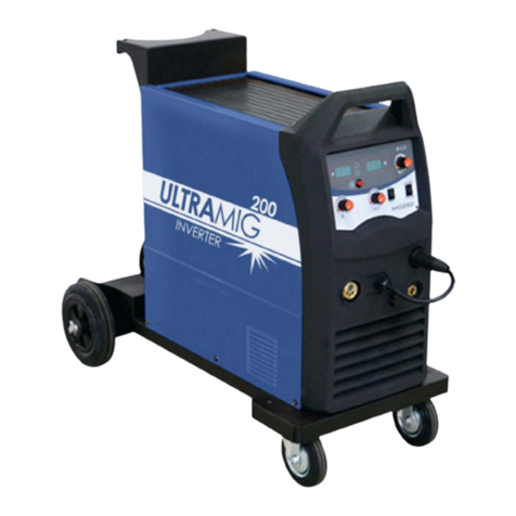
AMH UltraMig 175 User manual

UltraMig 175
- 1 -
U
Ul
lt
tr
ra
aM
Mi
ig
g
1
17
75
5
I
IN
NS
ST
TR
RU
UC
CT
TI
IO
ON
N
M
MA
AN
NU
UA
AL
L

UltraMig 175
- 2 -
Table of contents
SAFETY INSTRUCTIONS .................................................................................................................................4
1. Safety in the use of a power source for electric arc welding......................................................................4
2. Work station...............................................................................................................................................4
3. Servicing ....................................................................................................................................................4
4. Wire feed devices.......................................................................................................................................4
5. Maintenance...............................................................................................................................................4
6. Personal protection.....................................................................................................................................5
7. The face and eyes.......................................................................................................................................5
8. Safety against smoke, vapors, and noxious, toxic gases.............................................................................6
9. Safety in the use of gases ...........................................................................................................................6
GENERAL INFORMATIONS..............................................................................................................................7
1. Description of installation..........................................................................................................................7
2. Electrical connections ................................................................................................................................7
3. Installation equipment................................................................................................................................7
4. Operating instructions ................................................................................................................................8
FUNCTION AND SETTING................................................................................................................................9
1. Operating in synergic mode .......................................................................................................................9
2. Operating in manual mode.........................................................................................................................9
3. Thermal safety............................................................................................................................................9
4. Wire drive roller pressure adjustment ........................................................................................................9
5. Sheilding gas flow......................................................................................................................................9
6. Wire reel...................................................................................................................................................10
OPERATING AND WELDING INSTRUCTIONS ..............................................................................................11
1. How to hold the welding torch.................................................................................................................11
2. Welding steel............................................................................................................................................12
3. Aluminium welding..................................................................................................................................13
4. Spot welding.............................................................................................................................................13
5. Stitch welding...........................................................................................................................................13
6. Filling holes..............................................................................................................................................13

UltraMig 175
- 3 -
MAINTENANCE ...............................................................................................................................................14
1. Maintenance.............................................................................................................................................14
2. Installation................................................................................................................................................14
3. Troubleshooting .......................................................................................................................................14
EXPLODED VIEWS (ULTRAMIG 175).........................................................................................................16
EXPLODED VIEW (TORCH MB14)..............................................................................................................19
TECHNICAL INFORMATIONS ........................................................................................................................21
WARRANTY .....................................................................................................................................................22

UltraMig 175
- 4 -
Safety Instructions
1. Safety in the use of a power source
for electric arc welding
The equipment which you have just acquired will give
you complete satisfaction if you follow the operating
and maintenance instructions.
Its design, specification of components, and its
manufacture are in accordance with CE and ULC
standards.
When using this equipment, safety rules must be
observed, especially those concerning power sources.
For your safety, you will find listed below a complete
set of recommendations or requirements as found in
government labor safety codes.
2. Work station
The use of arc welding equipment requires the
establishment of strict safety conditions with regard to
electrical currents.
It is necessary to check that no metal on which an
operator will be working can come into direct or indirect
contact with a phase conductor and the ground of the
electrical supply network.
All ground cables for the welding operation that are
within reach of the user should be connected to a
single point.
All extension cords must be made with cables whose
wire size is at least equal to that of the largest power
cable.
If welding work has to be carried out in a confined
space, the following extra precautions should be taken:
• Increased individual protection.
• Complete insulation of the electrode holder, torches
or guns.
• The welding machine itself should be kept outside the
confined space and if this is not possible, the low
voltage parts of the equipment should be insulated and
the workpiece ground cable should be held in place by
solder.
3. Servicing
Before beginning any inspection or repair of the inside
of the machine it is necessary to make certain that the
equipment has been disconnected from the electrical
circuit by lockout and protective devices:
• The plug must be removed from the socket and
provisions are taken to prevent the accidental
connection of the plug in a socket.
• All cutout switches for fixed connection systems
should be omnipolar (phases and neutral). Such
switches must be in the "OFF" position, and secured or
“locked out” so that they cannot be accidentally put into
opération.
• Maintenance work on electrical equipment must be
undertaken only by persons qualified to do such work.
4. Wire feed devices
Make sure the wire or torch cannot touch any metal
parts, including the inside of the cabinet.
Do not allow the wire outlet or torch to point toward
your face or body.
Gloves should be worn when handling wire.
5. Maintenance
The insulation of equipment and the electrical
accessories must be checked regularly and kept in
good condition. This includes plugs, flexible cables,
sheaths, connectors, extension cords, workpiece
clamps or torches.
Maintenance and repair work on insulating sheaths and
covers should never be done in a makeshift manner.
AS REQUIRED:
• Replace defective accessories where possible.
Repairs should only be made by a trained specialist.
• Electrical connections must be checked regularly for
proper tightening and to insure they are not
overheating.

UltraMig 175
- 5 -
6. Personal protection
The operator must be dressed and protected in a
manner appropriate for the work being performed.
Precautions must be taken that no part of the body of
the operator or an assistant can come into contact with
workpieces or metal parts which might carry voltage
from the electrical system.
The operator must always wear individual insulating
protection.
The protective equipment worn by the operator and his
assistants (gloves, aprons, and safety shoes) must
provide additional protection against burns from hot
workpieces, spatter, and slag.
Protective equipment must be in good condition,
checked regularly, and replaced when worn or when no
longer serviceable.
7. The face and eyes
Every precaution must be taken to protect:
• The eyes against blinding glare from the welding arc.
(This includes visible light as well as infrared and
ultraviolet radiation).
• The hair and face against spatter and sparks.
The welding mask, whether or not it forms part of the
helmet, should always be fitted with a protective lens,
the DIN rating of which will depend on the intensity of
the welding arc current. See information:
"GUIDELINES FOR CHOOSING WELDING FILTERS
(conforming to EN 169 specifications)".
The colored filter may be protected from impact and
spatter by means of a transparent glass shield in front
of the mask.
When replacing the protective filter (tinted glass), care
must be taken to maintain the proper DIN rating (No of
opacity gradation).
Those in the vicinity of the operator, especially
assistants, must be protected by suitable screens or
protective goggles that block UV light, and if required,
by a mask equipped with a suitable protective filter.
1. Depending on the conditions of use, the next highest
or lowest category DIN number may be used.
2. The expression "heavy metals" covers steels,
alloyed steels, copper, and its alloys.
Note: The shaded areas represent applications
where the welding processes are not normally used
at present.

UltraMig 175
- 6 -
8. Safety against smoke, vapors, and
noxious, toxic gases
Arc welding work must be carried out only in suitably
ventilated areas.
The fumes emitted during welding in workshops should
be exhausted progressively as they are produced, as
closely as possible to their point of emission, and as
efficiently as possible.
Chlorinated solvents and their vapors, even at a
distance, are transformed into toxic gases when they
come in contact with welding arc radiation.
9. Safety in the use of gases
Comply with the safety recommendations given by the
supplier and in particular:
Avoid impact:
• Secure the cylinders and protect them from impact
with moving equipment and from being knocked over.
• Avoid excess heat (greater than 500 C/1220 F).
• Check that the pressure relief knob or screw is
backed off before connection to the cylinder.
• Check that the valve and regulator connections are
tight before opening the valve on the cylinder. Open it
slowly a fraction of a turn.
• If there is a leak, never tighten a connection which is
under pressure. First close the valve on the cylinder.
• Always check that hoses are in good condition.

UltraMig 175
- 7 -
General informations
1. Description of installation
The UltraMig 175 is a SYNERGIC AND MANUAL MIG
welding unit which uses a thyristor-based power
source controlled by a microprocessor with remote
opération.
The microprocessor provides synchronized adjustment
of the welding voltage and the wire feed speed by
means of a single control knob on the torch
(SYNERGIC control). Also controls the welding cycle
(striking the arc and the end of the weld) and the
thermal safety devices.
2. Electrical connections
The welding machine is delivered with its primary or
input power cable already attached. The power supply
should be protected by a system of fuses or circuit
breakers matching the primary draw of the machines.
3. Installation equipment
3.1 Wire feed unit
The drive unit comes fitted with one set of rollers which
will accept wire sizes of 0.6 and 0.8mm (.024” and
.030”).
3.2 Torch
The UltraMig 175 is delivered equipped with a torch,
tips, and accessories for 0.6 and 0.8mm (.024” and
.030”) size wire.
3.3 Ground cable connection
The UltraMig 175 comes with a ground cable already
attached to the machine. It is possible to change the
polarity of the ground cable according to the type of
welding wire used as follows:
A. Attach the ground cable lug to one of the terminals (+
or -), located immediately on top of the wire feeder; (to
the “+” if you use a shielded (flux core) wire and to the “-
” if you use solid wire).
B. Attach the other wire coming from the electrical side
to the other terminal.

UltraMig 175
- 8 -
3.4 Gas connections
A. Open the cylinder valve slightly to remove any
impurities and close it immediately.
B. Install the pressure regulator and flow rate meter.
C. Connect the supplied gas hose from the machine to
the regulator.
D. Open the gas cylinder.
4. Operating instructions
A. Connect the unit to a 220 Volt 15 amp outlet.
B. Turn the main switch on the control panel to the on
( “I”) position.
C. Select either the “SYNERGIC” or “MANUAL”
option.
Loading the wire drive:
- Unscrew the tension bolt of the upper wheel and
remove the roller.
- Feed the wire into the inlet guide tube until it engages
in the groove of the drive roller and feeds into the gun
liner on the right side of the roller.
- Re-install the upper roller and the tension bolt.
NOTE: Make sure that the tension is not set too tight
and that the wire will run freely.
- Turn the control knob on the torch to the maximum
and feed the wire through the cable by pulling the
trigger with the torch cable extended.
- While the wire is feeding, adjust the gas flow rate
(trigger pulled).
STEEL: 75/15 AR/CO210 – 16L/mn ALUMINIUM: 100% Argon 14 – 20L/mn

UltraMig 175
- 9 -
Function and setting
1. Operating in synergic mode
During semi-automatic MIG welding, "operating in
synergic mode" means that with a single control knob
(on the torch), the wire feed and the welding voltage
are adjusted AT THE SAME TIME and synchronized.
All the combinations (wire feed speed & voltage) have
been stored in the microprocessor's memory.
A) Turn the knob ont the torch to increase or decrease
the wire feed and the power according to the thickness
of the metal being welded.
NOTE: It’s better to set a low output at the start and
increase it gradually. This will avoid damaging thework
piece.
B) The wire feed may be fine tuned by using the knob
(- or +) on the front control panel. This fine tuning of
the wire speed is possible regardless of wire size or
type. Once fine tuned, the synergic control on the torch
continues to synchronize the feed and voltage. This
allows the operator to adjust the unit while welding in
any position (e.g. upside down or vertical) without
returning to the panel.
2. Operating in manual mode
In MANUAL welding mode, the control knob on the
torch will control only the welding wire speed while the
knob on the front control panel will be used only to
control the welding voltage. This is means that the
operator will be able to control the welding power and
the welding wire speed separately.
3. Thermal safety
The YELLOW indicator on the front control panel will
light up if the transformer overheats. Once it has
cooled, the indicator light goes off and the transformer
will start up with the same set-up as before the thermal
safety shut it down.
4. Wire drive roller pressure
adjustment
Pressure on the drive roller system is adjusted by
turning the bolt of the upper roller. The pressure
setting is correct when:
A. The wire feeds out smoothly.
B. The rollers slip on the wire if the wire jams or
freezes at the nozzle without the wire "birdnesting"
between the rollers and the wire outlet guide.
5. Sheilding gas flow
The major function of the gas flow during the welding
process, is to protect the melting point from the
contamination. To obtain the optimum of that
protection, there is a delay of one seconde between
the shut off of the welding arc and the end of the gas
flow protection. That over flow will permit an
additionnal protection of the melting point again the
oxydation and a better cooling of the welding tip and
nozzle. That post flow will help us to do stitch welding
under continius gas protection.

UltraMig 175
- 10 -
6. Wire reel
Installing the reel :
The unit is shipped with a reel cone set to be mounted
as shown in fig. 1:
1. First install a flat washer, then the spring, a flat
washer, and the male cone.
2. Install the reel with the wire feeding from the bottom
(fig. 2)
3. Finish the setup with the outer cone, then the lock
washer, and the wingnut until the reel is lightly
clamped.
4. Run the machine with the wire feed speed set to
maximum (adjust on torch). Test the tension by
jamming the wire at the nozzle. The rollers should slip
and the wire should not continue to be fed. There
should be no “birdnesting.”
ATTENTION : Do not adjust the wingnut on the reel
too tightly as this will make the wire feed motion erratic
causing the arc to sputter.
Figure 1
Figure 2

UltraMig 175
- 11 -
Operating and welding instructions
1. How to hold the welding torch
When approaching the working piece with the welding
torch, it is important to use the following technique:
A. Slope the torch at an angle between 45oto 60oto
the work surface and direction of the weld.
B. For the best results, the operator should move at an
appropriate angle for the work being done.
C. THE TORCH SHOULD NOT BE MOVED AWAY
FROM THE SURFACE ONCE WELDING HAS
BEGUN. Pulling back the torch causes very poor weld
quality and generates spatter. The distance between
the welding nozzle and the workpiece should be about
6mm (1/4”).
D. Two basic welding techniques may be used. (see
fig. 1)
Figure 1
In most cases, the speed with which the welding torch
is moved will determine the shape of the weld bead.
The average torch speed is from 40 cm to 50 cm/min
(15 to 20 inches/min.). A mixture with ARGON and
CO2(ex. 75/25) gas is a good choice for welding
regular steel, especially for achieving a clean, strong
weld. Pure argon is used for welding aluminum.
Argon gas may only be used for welding steel when it
is mixed with CO2. NOTE: All gases are supplied
from the cylinder under very high pressure (from 2000
psi - 150 kg/cm2to 3000 psi - 200 kg/cm2). A properly
rated gas regulator is required to lower that pressure.

UltraMig 175
- 12 -
2. Welding steel
A. Use a gas mixture of 25% CO2 and 75% ARGON
with a 10 to 16 l/min flow.
B. Use the correct wire size and contact tip to match
(0.6 tip for .023 wire, etc.).
C. Hold the welding torch as described before.If the
torch is held further away from the work, it will result by
a wider and thinner weld bead. (see fig. 2).
D. Begin welding by turning the control knob on the
torch to its lowest position and pull the trigger.
Gradually increase the setting until the arc is steady
and even.
E. When welding on a slope (fig. 3), the penetration of
the weld will decrease as the slope increases. The
weakest penetration occurs during vertical and
overhead welding.
F. It is advantageous to use a larger wire size on thick
material in order to obtain a correct, safe level of
penetration. A larger wire size allows a higher welding
current output.
G. Gas pressure will need to be increased in sloped,
vertical, and upside down positions, and in places
where the workpiece in not very clean (e.g. a wheel
well).
Figure 2
Figure 3

UltraMig 175
- 13 -
3. Aluminium welding
A. Aluminum welding with a standard torch normally
requires the installation of a teflon liner in a size to
match the gun and cable assembly.
B. Reduce the tension on the upper drive wheel.
There should be just enough drag to feed the torch
without damage to the aluminum wire (see fig.).
C. Use only 100% argon inert gas with 14 to 18 l/min
flow rate.
D. Always "PUSH" the weld bead with aluminum to
keep the gas "IN FRONT" of the welding. The argon
will provide the inert shield for a clean weld. E) Use a
stainless steel brush to clean the aluminum before the
welding.
F. Begin with a low power setting and gradually
increase it obtain a smooth, even weld.
G. As aluminum is an excellent heat conductor, it will
be necessary to decrease the power after few
centimetres (inches) of welding.
NOTE: Always use a contact tip one size bigger then
the aluminum welding wire selected. Ex: for a wire of
0.8mm (.030”), use a contact tip for a wire diameter
of 0.9mm (.035”).
4. Spot welding
Spot welding can be done through two thickness of
sheet metal. However, the best results are obtained by
drilling or punching a hole the top piece.
A. In case of spot welding through two pieces of sheet
metal, both pieces should be clean, properly aligned,
and securely clamped together.
B. Install the spot weld nozzle on the torch.
C. Adjust the power to obtain a flat bead. If possible,
test the setting on a sample made with the same
sheets of metal to be spot welded.
D. Hold the torch perpendicular to the work surface
with the two spot nozzle legs touching the metal and
pull the trigger.
E. In case of welding in a pre-drilled hole, center the
spot nozzle above of the hole and fill it up.
F. When working without a pre-drilled hole it will be
necessary to turn up the power high enough to
penetrate the top sheet of steel.
G. When a spot nozzle is not available, use a standard
conical welding nozzle and maintain a distance of
6mm to 12mm between the nozzle and the sheet
metal.
5. Stitch welding
Stitch welding is a convenient process to use when
welding rusty or thin material, and where there is a risk
of deforming or burning through the metal. A stitch
weld actually consists of a series of spot welds strung
together. A short gap between each stitch allows the
piece of steel to cool down.
A. Select a power setting appropriate for the thickness
of the piece of steel.
B. Hold the trigger and move slowly along the welding
line while maintaining the angle to and distance from
the work.
C. The gap between each stitch should be long
enough to allow the orange color of the preceding weld
to disappear.
A build in “post” gas flow of 1 sec. keeps the gas valve
open after the arc stops providing better cooling before
the next weld.
6. Filling holes
A. Throughly clean the edges of the hole.
B. Make a short weld at one spot on the edge of the
hole and let cool.
C. Make another short weld on each side of the first
weld and let them cool.
D. Make two longer welds overlapping the first three
with an arching movement of the torch. Again, allow
the welds to cool.
E. Repeat the same technique on the other side of the
hole and across the top of the hole, if necessary.
F. Long, narrow gaps may also be easily filed and
closed by using the stitch welding mode.

UltraMig 175
- 14 -
Maintenance
1. Maintenance
Periodically (at least every 6 months, depending upon
the extent to which the unit has been used) check:
- The cleanliness of the unit.
- The condition of electrical and gas hoses
connections.
WARNING: Never clean or work inside the unit
without first making sure that it is indeed
disconnected from the outlet.
Remove the transformer side panel and using a blower
with compressed air, remove all metal particles and
dust that has accumulated between the windings of
the transformer and on all the other internal parts.
While cleaning the interior, inspect for any damage to
the electrical connections of the power cord, the
control and power supply circuits, and the condition of
cable insulation, couplings and hoses.
WIRE DRIVE SYSTEM
On a regular basis, use dry compressed air to clean all
parts of the drive system.
ROLLERS AND WIRE GUIDE
Under normal conditions of use, the rollers and wire
guides should give a long period of service before any
replacement becomes necessary. After being
operated for a certain period of time, however, excess
wear or clogging due to metal deposits might appear.
Regular cleaning will help to minimize such effects
which detract from proper operation. The drive motor
itself does not require any maintenance or lubrication.
2. Installation
Regularly check that all connections for the supply of
current to the machine and the torch are tight such as:
- contact tip
- coaxial cable
- welding nozzle
Mechanical stresses due to thermal shock can tend to
unloosen certain parts, in particular those on the torch.
Remove any spatter accumulated between the contact
tip and the nozzle.Spatter can be removed more easily
when this is done often. Do not use any hard tool
which might scar the surfaces of these parts. Rough
surfaces make it easier for spatter to stick. Whenever
possible, use products designed to control the
adherence of spatter.
Blow dry compressed air through the cable liner after
each wire spool change. Carry out this procedure from
the motor side of the torch cable.
Contact tips are designed for prolonged use. They are
nevertheless worn by the passage of the wire and the
hole eventually becomes larger than the acceptable
tolerance for good contact between the tip and the
wire. The need for replacement becomes apparent
when the arc sputters even though all other
adjustment parameters appear to be correct.
3. Troubleshooting
In the event of any malfunction and before looking for
the cause, TAKE EXTREME CARE TO:
- Disconnect the machine from the outlet.
- Check the electrical connections of the input power
circuit.
- Check the electrical connections of the control and
output power circuit (electronic circuit connectors,
fuse, etc.).
- Check the condition of cable insulation (heating or
burns can be signs of a fault).
- Check the condition of the lines and couplings of the
gas circuit.
- Check the electrical power supply (fuses or circuit
breakers).

UltraMig 175
- 15 -
Situation Action
Wire does not feed
Check the fuse.
Check voltage.
If voltage OK, replace the motor reducing gear set.
No gas
Check the condition of the cylinder.
Check the condition of the pressure regulator and the hose.
Check if there is 24 V on the selenoid valve.
No welding current
Check between the - and + terminals on the capacitor.
Check the ground clamp.
Otherwise, disconnect the power source from the mains and test the choke,
the capacitors, the resistor, the transformers and all the connections.
Otherwise, replace the electronic board.
Erratic wire feed
Check whether the reel is too tightly clamped (adjust if necessary).
Check whether the rollers are damage.
Check whether the rollers are too loose (adjust if necessary).
Check whether the torch cable is damage.
Check whether the wire conduct is blocked (blow out).
Check whether the wire is intermix.
Be sure that the contact tube is the right diameter for the wire.
Arc unstable
Check the capacitor connections unloosen.
Check the wire clamp contacts.
Check the potentiometer- the gas flow rate.
Check the condition of the contact tube (replace)
HOT indicator lit
The set is overheating. Wait 10 to 15 mins until the indicator goes off.
Clean regularly the welder.
If problem(s) persist, contact your dealer

UltraMig 175
- 16 -
Exploded views (UltraMig 175)

UltraMig 175
- 17 -

UltraMig 175
- 18 -
NO No. AMH DESCRIPTION QTY
1 51.600.02.53 ROCKER SWITCH 1
2 09.125.01.15 CONTROL KNOB 1
3 27.800.01.35 CIRCUIT BOARD 1
4 17.100.00.50 MAIN SWITCH 1
5 07.123.00.21 12V TRANSFORMER 1
6 07.123.00.26 24V TRANSFORMER 1
7 17.800.01.30 BLEEDER RESISTOR 1
8 17.800.02.10 GAS VALVE 1
9 10.800.10.65 GAS HOLE 1
10 01.138.01.11 AC CABLE 1
11 17.115.00.05 FAN 1
12 07.800.05.14 CHOKE 1
13 31.162.00.30 CAPACITOR BRACKET 1
14 10.135.00.33 HEAT SINK (+) 1
15 10.135.00.34 HEAT SINK (-) 1
16 17.100.00.10 CAPACITOR 1
17 10.135.00.24 DEREELER PLATE 1
18 07.800.05.15 MAIN TRANSFO 1
19 10.800.00.50 COMPLETE TRIAC 1
20 01.800.00.03 GROUND CABLE 1
21 03.600.00.06 MB14 TORCH ASSY 1
22 08.142.02.06 NO8TOOTH WASHER 8
23 08.141.04.00 M4 NUT 8
24 08.141.06.27 M6 BRASS BOLT 2
25 08.141.06.01 M6 BRASS NUT 4
26 51.600.03.13 FUSE HOLDER 1
27 51.608.00.03 3A FUSE 1
28 10.135.00.30 POLARITY INSULATION 1
29 08.141.04.20 M4 X 20 BOLT 4
30 08.141.06.02 M6 WING NUT 2
31 08.141.04.60 M4 X 60 BOLT 4
32 08.148.08.10 NO6X 5/8 SCREW 1
33 15.800.00.20 FEEDER 1
34 08.141.04.10 M4 X 10 BOLT 4
35 02.205.08.52 M12 X 1HEX NUT 1
36 02.800.00.02 MOTOR QUICK ADAPTER 1

UltraMig 175
- 19 -
Exploded view (Torch MB14)

UltraMig 175
- 20 -
NO No. AMH DESCRIPTION QTY
1 02.205.01.77 LONG BOLT 2
2 02.205.01.78 SHORT BOLT 2
3 03.203.02.03 UPPER PART HANDLE 1
4 02.205.01.10 SPACER BUSHING 2
5 03.203.01.05 TORCH CABLE 3M 1
5B 03.203.01.06 TORCH CABLE 4M 1
6 02.205.01.45 CABLE SUPPORT 1
7 02.205.01.75 LOCK NUT 2
8 02.205.01.55 TORCH BODY SEAT 1
9 02.205.01.40 TORCH BODY 1
10 02.205.01.86 SWAN NECK 1
11 02.205.01.20 HEAD INSULATOR 1
12 04.204.90.05 GAS DIFFUSOR 1
13 02.205.01.25 SPRING NOZZLE 1
14A 04.204.00.01 TIP .024" (0.6MM) 1
14B 04.204.01.01 TIP .030" (0.8MM) 1
14C 04.204.02.01 TIP .035" (0.9MM) 1
14D 04.204.03.01 TIP .045" (1.2MM) 1
15 05.202.01.05 CONICAL NOZZLE 1
16 05.202.01.10 CYLINDRICAL NOZZLE 1
17 05.202.01.15 SPOT WELD NOZZLE 1
18 05.202.01.20 STUD WELD NOZZLE 1
19 02.205.08.25 KNOB 1
20 37OR007 ORING NO7 1
21 17.102.00.03 HEX NUT 1
22 17.102.00.04 POTENTIOMETER SUPPORT 1
23 17.102.00.05 POTENTIOMETER 1
24 03.203.02.03 LOWER PART HANDLE 1
25 02.205.01.76 HANDLE NUT 4
26 02.205.01.66 SPRING SUPPORT 1
27 02.205.01.65 SPRING (LARGE) 1
28 02.205.08.34 LINER NUT 1
29 06.206.00.10 STEEL LINER 1
30 02.205.08.49 MOTOR ADAPTOR 1
31 02.205.01.67 SWITCH ASSY 1
32 02.205.01.64 SPRING (SMALL) 1
33 02.205.01.63 TRIGGER 1
Table of contents
Other AMH Welding System manuals
Popular Welding System manuals by other brands

SteelMax
SteelMax ARC Runner Operator's manual

TradeWeld
TradeWeld GENX MIG2800S INDUSPRO owner's manual

ESAB
ESAB LHJ 425 instruction manual

flopower
flopower FLOW160DA000 Operator's manual and parts list

Lincoln Electric
Lincoln Electric Invertec V160-T Operator's manual

ESAB
ESAB POWERCUT-1500 instruction manual