SteelMax ARC Runner User manual
The tools of innovation.
15335 E. Freemont Drive, CO 80112
1–87STEELMAX, FAX 303 –690 –9172
www.steelmax.com [email protected]
OPERATOR’S MANUAL
A
AR
RC
C
R
Ru
un
nn
ne
er
r
WELDING CARRIAGE

Contents
1.GENERAL INFORMATION................................................................................................ 3
1.1. Application................................................................................................................. 3
1.2. Technical data............................................................................................................ 3
1.3. Equipment included ................................................................................................... 4
1.4. Dimensions................................................................................................................ 5
1.5. Design ....................................................................................................................... 6
2.SAFETY PRECAUTIONS.................................................................................................. 7
3.STARTUP AND OPERATION............................................................................................ 9
3.1. Preparing................................................................................................................... 9
3.2. Connecting to the welding circuits.............................................................................10
3.3. Positioning at the worksite ........................................................................................11
3.4. Starting.....................................................................................................................13
3.5. Programming............................................................................................................13
3.6. Welding procedure....................................................................................................15
3.7. Operating..................................................................................................................16
3.8. Using oscillator (option).............................................................................................17
3.9. Troubleshooting........................................................................................................20
4.MAINTENANCE ...............................................................................................................21
5.ACCESSORIES................................................................................................................22
5.1. Oscillator...................................................................................................................22
5.2. Torch clamps............................................................................................................24
5.3. Rods.........................................................................................................................25
5.4. Torch holders............................................................................................................26
5.5. Torch extension arm .................................................................................................28
5.6. Guide arms...............................................................................................................29
5.7. Dual torch mount.......................................................................................................34
5.8. Flexible guide set......................................................................................................35
5.9. Guide adjustment tool...............................................................................................37
5.10. 76 mm cross slide...................................................................................................38
5.11. Display protection shield .........................................................................................39
5.12. Fall arrester.............................................................................................................39
5.13. Stainless steel wheels.............................................................................................40
6.115–230 V EXPLODED VIEWS AND PARTS LIST..........................................................41
7.42 V EXPLODED VIEWS AND PARTS LIST....................................................................46
8.115–230 V WIRING DIAGRAM.........................................................................................51
9.42 V WIRING DIAGRAM ..................................................................................................52
10. DECLARATION OF CONFORMITY...............................................................................53
11. WARRANTY CARD........................................................................................................54

ARC Runner
ARC Runner Operator’s Manual
3
1. GENERAL INFORMATION
1.1. Application
The ARC Runner is a welding carriage designed to make butt and fillet welds that are
continuous or stitch. The carriage allows MIG/MAG torches and is clamped with
permanent magnets.
Accessories allow welding with oscillation, using torches with a larger diameter
and using two torches at the same time. They also allow the carriage to move along
outside edges, lap joints and templates, walls that are low or have holes, and on
ceilings, pipes, and tanks.
1.2. Technical data
Voltage
1~ 115–230 V, 50–60 Hz
1~ 42 V, 50–60 Hz (60 V DC)
Power
25 W
Welding position (according to
EN ISO 6947 and AWS/ASME)
Horizontal
PA/1F/1G
PB/2F
PC/2G
PD/4F
PE/4G
Vertical
PF/3F/3G (with an optional oscillator)
PG/3F/3G (with an optional oscillator)
Minimum path curve radius
1500 mm (5 ft)
Torch type
MIG/MAG
Torch diameter
16–22 mm (0.63–0.87″)
Maximum torch reach
80 mm (3.15″)
Maximum allowed cable weight
Horizontal work
12 kg (27 lbs)
Vertical work
8 kg (18 lbs)
Minimum workpiece thickness
5 mm (0.2″)
Ground clearance
5 mm (0.2″)
Horizontal pulling force
220 N (48 lbs)
Vertical pulling force
150 N (33 lbs)
Cross slide adjustment range
0–35 mm (0–1.38″)
up-down, left-right
Guide arm adjustment range
0–75 mm (2.95″)
Horizontal speed
0–120 cm/min (0–47.2 in/min)
Vertical speed
0–110 cm/min (0–43.3 in/min)
Noise level
Less than 70 dB
Weight
14 kg (31 lbs)
ARC Runner
ARC Runner Operator’s Manual
4
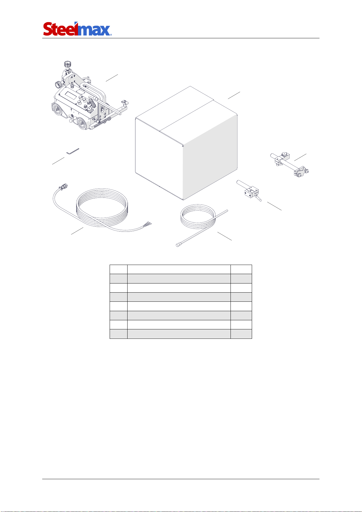
1.3. Equipment included
1
Carriage
1 unit
2
Cardboard box
1 unit
3
Cable anchor
1 unit
4
Short rod torch holder with clip
1 unit
5
3 m (10 ft) power cord
1 unit
6
6.5 m (21 ft) arc ignition cable
1 unit
7
4 mm hex wrench
1 unit
–
Operator’s Manual
1 unit
1
2
3
4
5
6
7
ARC Runner
ARC Runner Operator’s Manual
5
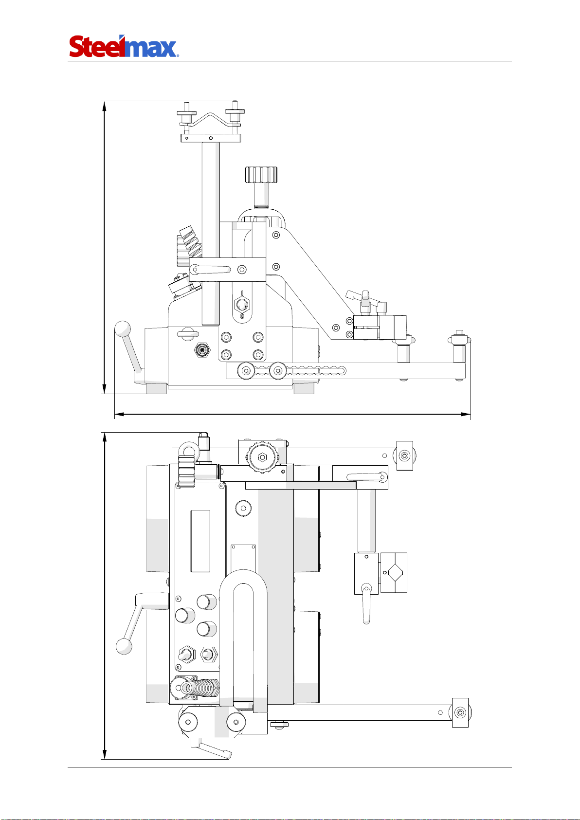
1.4. Dimensions
411 mm (16.2″)
368 mm (14.5″)
447 mm (17.6″)
ARC Runner
ARC Runner Operator’s Manual
6
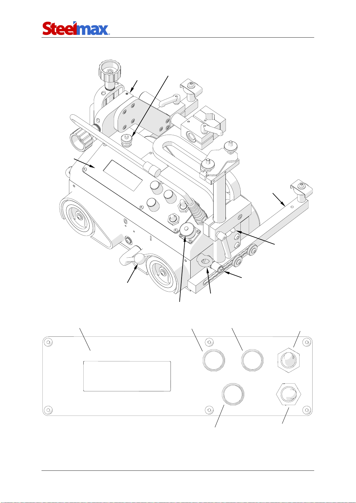
1.5. Design
Lug for fall arrester
Arc ignition socket
Control panel
Cross slide
Oscillation socket
Guide arm
Power switch
Limit switch
Magnet lever
LCD display
Knob F1
Knob F2
Arc ignition switch
(TEST / O / I)
Travel direction switch
(Left / O / Right)
Speed adjustment knob

ARC Runner
ARC Runner Operator’s Manual
7
2. SAFETY PRECAUTIONS
1. Before use, read this Operator’s Manual and complete a training in occupational
safety and health.
2. Use only in applications specified in this Operator’s Manual.
3. Make sure that the carriage has all parts and they are genuine and not damaged.
4. Make sure that the specifications of the power source are the same as those
specified on the rating plate.
5. Connect the carriage to a correctly grounded power source.
6. Do not carry the carriage by the cords or arc ignition cable, and do not pull them.
This can cause damage and electric shock.
7. Keep untrained bystanders away from the carriage.
8. Before each use, ensure the correct condition of the carriage, power source,
cords, arc ignition cable, plugs, sockets, control panel, and wheels.
9. Before each use, make sure that no part is cracked or loose. Make sure to main-
tain correct conditions that can have an effect on the operation of the carriage.
10. Keep the carriage dry. Do not expose the carriage to rain, snow, or frost.
11. Keep the worksite well lit, clean, and free of obstacles.
12. Do not use near flammable materials, or in explosive environments.
13. Make sure that the rubber of the wheels is clean and not damaged.
14. Do not remove the cover of the wheels.
15. Remove objects attracted to the chassis by the magnet.
16. Transport and position the carriage by using the carrying handle and only after
you set the magnet lever to ‘O’.
17. Put the carriage so that four wheels are on the surface. Make sure that no con-
tact is between the surface and chassis.
18. Do not stay below the carriage that is put at heights.
19. Connect the cords and arc ignition cable only after you set the power switch to
‘O’.
20. Keep the sockets clean. Do not use high pressure during cleaning.
21. Install only MIG/MAG torches whose diameter matches the diameter of the torch
holder.
22. Do not put the torch more than 80 mm (3.15″) outward from the left or right side
of the carriage.

ARC Runner
ARC Runner Operator’s Manual
8
23. Keep the torch cables away from the surface. Hang the cables to decrease the
load applied on the carriage. Use only cables whose weight is not more than 12
kg (27 lbs) for horizontal work and 8 kg (18 lbs) for vertical work.
24. Do not work on curves with convex or concave radius less than 1500 mm (5 ft).
25. At heights, use a fall arrester not to let the carriage fall.
26. Use eye protection (helmet, shield, and screen), ear protection, gloves, and
protective clothing. Do not use loose clothing.
27. Do not stop the carriage by hand. To stop, set the travel direction switch to ‘O’.
28. Do the maintenance only after you unplug the carriage from the power source.
29. Repair only in a service center appointed by the seller.
30. If the carriage falls, is wet, or has any damage, stop the work and promptly send
the carriage to the service center for check and repair.
31. Do not leave the carriage unattended during work.
32. If you are not going to use the carriage, remove it from the worksite and keep in a
safe and dry place.
ARC Runner
ARC Runner Operator’s Manual
9
3. STARTUP AND OPERATION
3.1. Preparing
Use the carrying handle to transport the carriage to the worksite. Then, set to ‘O’ all
switches (power, travel direction, and arc ignition switch) and the magnet lever.
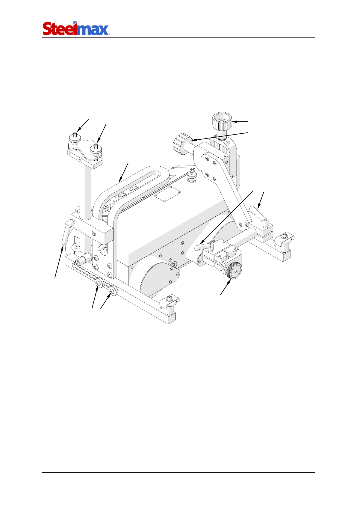
Fig. 1. View from the back side
Use the power cord to connect the carriage to the power source. Then, put the
torch into the torch holder and tighten with the knob. Put the torch cables into the
cable anchor and tighten with the knobs.
Knobs for
precise torch
adjustment
Knobs to secure the
cable in the anchor
Lever to secure the
cable anchor
Knob to secure the torch
in the holder
Levers to secure
the torch position and
angle
Screws to secure the guide arm
Carrying handle
ARC Runner
ARC Runner Operator’s Manual
10
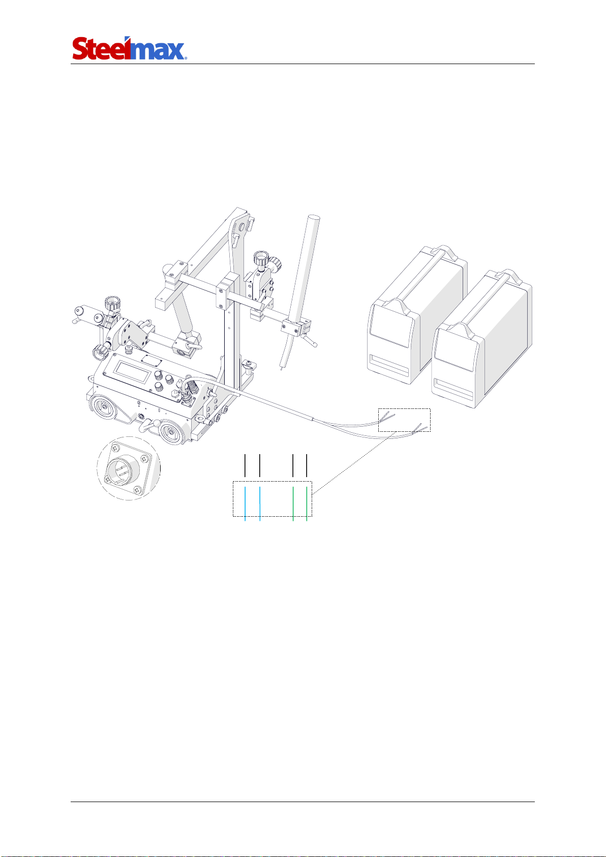
3.2. Connecting to the welding circuits
The carriage can control two torches by using the arc ignition cable plugged into the
arc ignition socket. To do this, refer to the diagram from Fig. 2 and connect one blue-
jacketed wire to one terminal of the welding circuit. Then, connect the other blue-
jacketed wire to the other terminal of the same circuit. To control the second torch,
connect the green-jacketed wires to the terminals of the second welding circuit.
Fig. 1. Connecting the arc ignition cable to welding circuits
Make sure that the arc ignition cable is connected correctly. To do this, turn on the
power of the carriage, and then set the arc ignition switch to TEST. This should
enable the arc for a while.
blue
blue
Welding circuit 1
green
green
Welding circuit 2

ARC Runner
ARC Runner Operator’s Manual
11
3.3. Positioning at the worksite
Put the guide arms so that the carriage is in constant contact with the workpiece. You
can set them by a constant step (interval adjustment), or continuously after you swap
them (continuous adjustment). To set them correctly when the carriage moves to the
left, use the 4 mm hex wrench to loosen the screws that secure the right guide arm.
Next, move out the right arm about 10 mm (0.4″) or one groove more than the
left arm (Fig. 3), and then tighten the screws again.
Fig. 2. Correct positioning of the guide arms
The roller assemblies may be installed at
the other end of the guide arms
Interval adjustment
Travel direction
Continuous adjustment
Swap the guide arms
to change between
methods of adjustment
Grooves
Moving out the right arm
by one groove
Lug for fall arrester

ARC Runner
ARC Runner Operator’s Manual
12
To put the carriage closer to the workpiece, use the 4 mm hex wrench to remove
the roller assemblies. Next, install them at the other end of the guide arms, and then
swap the guide arms (Fig. 3).
Switch the magnet lever from left (‘O’) to right (‘I’). This will change the clamping
force from minimum to maximum. Loosen the levers to adjust the position and angle
of the torch. Use two knobs at the cross slide to precisely set the torch position.
At heights, attach a fall arrester (not included) to a lug (Fig. 3) to prevent fall of
the carriage. This will avoid possible injury to the operator in case the carriage loses
the clamping. Do not stay below the carriage that is put at heights.
ARC Runner
ARC Runner Operator’s Manual
13
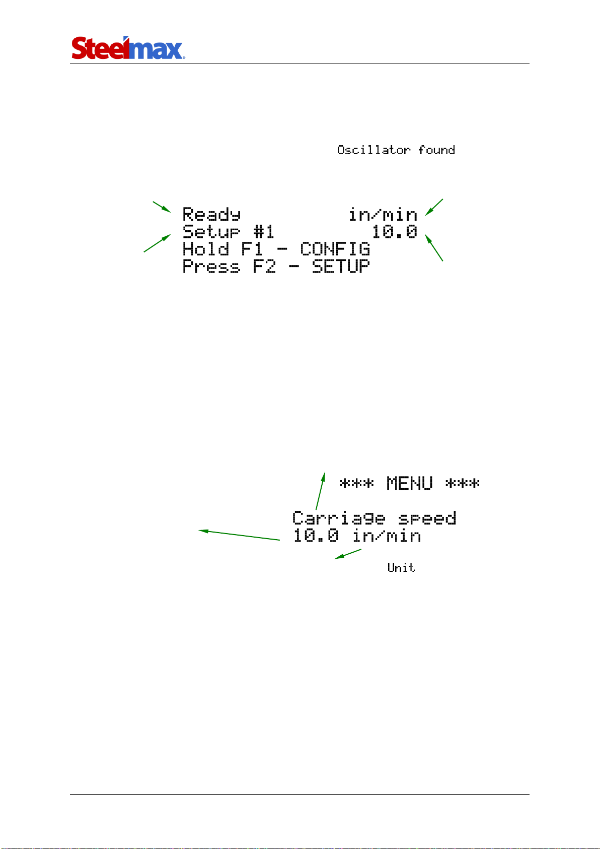
3.4. Starting
Plug the power cord into the power source and set the power switch to ‘I’ to turn on
the carriage. Then, an initial screen with the current firmware number shows. If an
oscillator is connected to the oscillation socket, shows. After
the control system is loaded, the main menu from Fig. 4 shows.
Fig. 1.View of the main menu
Press and hold the knob F1 for about 3 seconds to go into the configuration
menu and set the welding parameters.
3.5. Programming
The carriage allows you to define up to 40 welding programs. After you go to the
configuration menu, continue as described in Fig. 5.
Fig. 2.Configuration menu
Current operating mode
Program
number
Unit of speed
Value of
speed
Name of parameter. Rotate the knob F1 to
change among parameters shown in Tab. 1.
Value of parameter. Rotate the
knob F2 to change the value by the
higher step shown in Tab. 1. Press
and rotate the knob F2 to change
the value by the lower step.
Unit of parameter. Can be changed from the setting.
ARC Runner
ARC Runner Operator’s Manual
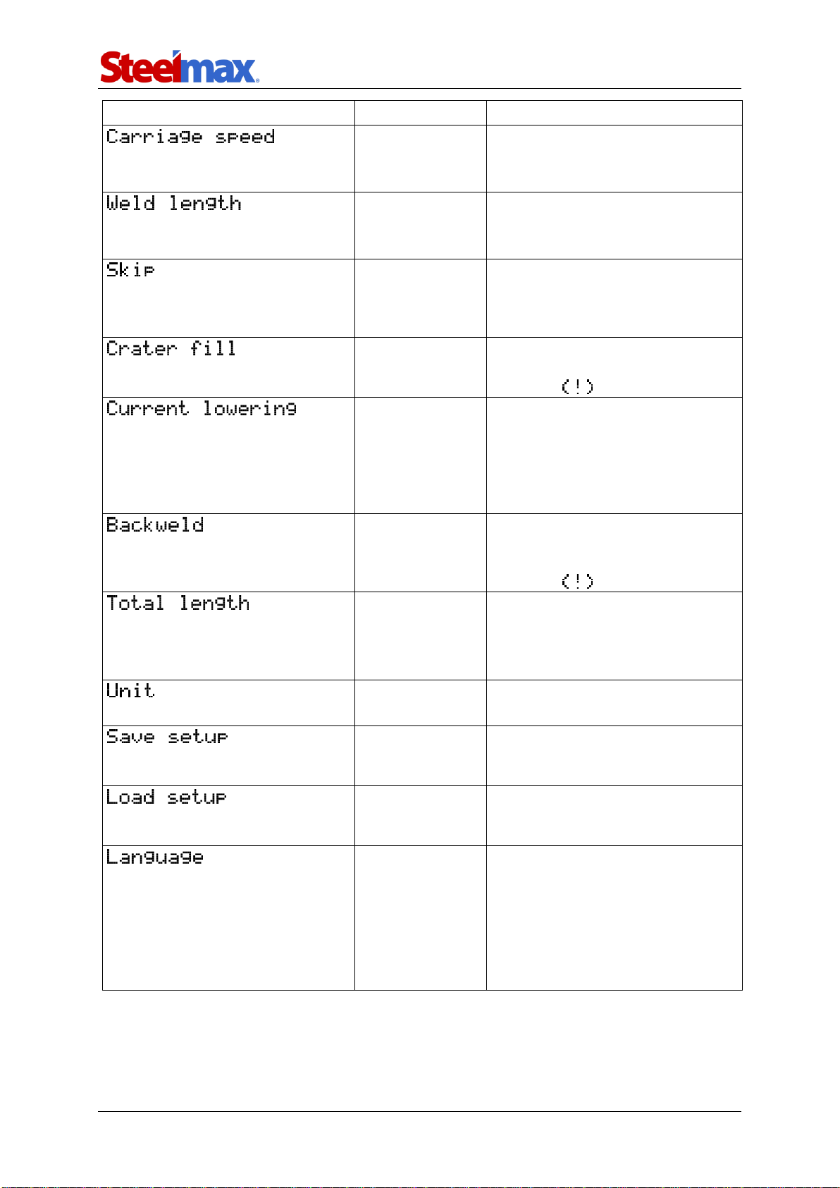
14
Parameter
Value
Description
0–130 cm/min
0–52 in/min
[step: 1 or 0.1]
Speed of the carriage.
1–250 cm
1–100 in
[step: 1 or 0.1]
Length of a single weld.
0–100 cm
0–40 in
[step: 1 or 0.1]
Space between welds. If set to
zero, ‘crater fill’ and ‘backweld’ are
reset and the carriage works in
the continuous welding mode.
0–3 s
[step: 0.1]
Time of filling the crater. Inactive if
‘skip’ set to zero, which is indicat-
ed by the sign.
YES
NO
Function of the welding source to
lower the current of the arc while
filling the crater. Time of filling the
crater must be set higher or equal
to the time of the current lowering
that is set at the welding source.
0–2 cm
0–2 in
[step: 0.1]
Length of the backweld. Shorter or
equal to ‘weld length’. Inactive if
‘skip’ set to zero, which is indicat-
ed by the sign.
0–1000 cm
0–400 in
infinity
[step: 10 or 1]
Longer or equal to the sum of
‘weld length’ and ‘skip’. If set to
infinity, the program executes until
you stop the carriage.
cm
in
Unit used in the menu.
1–40
Pressing knob F2 saves the
current configuration to the indi-
cated program number.
1–40
Pressing knob F2 loads the
configuration from the indicated
program number.
ENGLISH
POLISH SPAN-
ISH FRENCH
PORTUGUESE
TURKISH
GERMAN
RUSSIAN
Language of the menu.
Tab. 1. Settings available in basic version of the carriage
ARC Runner
ARC Runner Operator’s Manual
15
To change the language of the menu, go to setting by rotating the
knob F1 to the right, and then rotate the knob F2 to choose among the available
languages. After the rest of the parameters from Tab. 1 is set, go to ,
choose a program number by rotating the knob F2, and press the knob to save the
current values to this number. The message shows for a short time. To load
a previously saved program, continue as described, but from setting.
To go back to the main menu (Fig. 4), press the knob F1 and hold it for 3 seconds. If
you do not save the chosen parameters, they will be active only until you change the
current program number in the main menu.
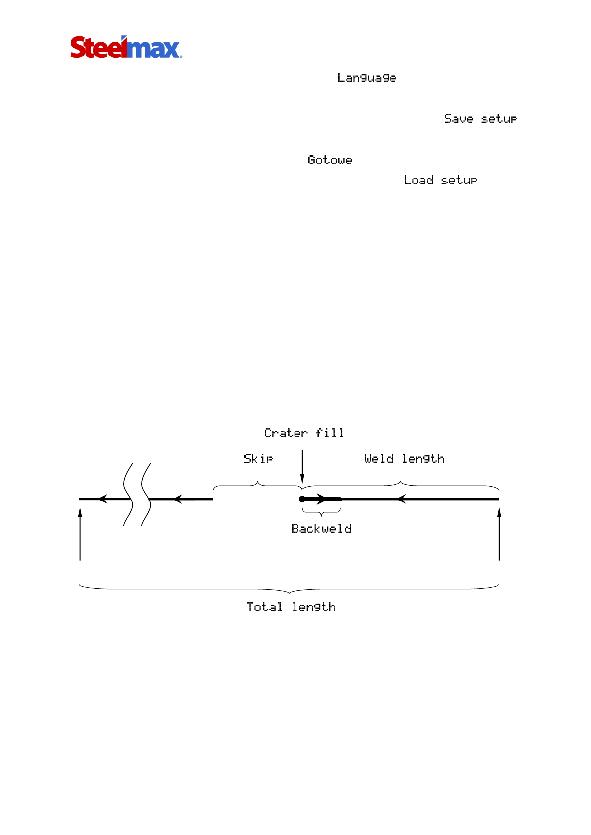
3.6. Welding procedure
Fig. 6 shows a graphic description of the welding procedure that starts with the speed
value shown in the main menu when you select a travel direction. The first stage is
making the weld, and then the carriage fills the crater (stage 2) for the chosen time.
Next, the carriage does the backweld (stage 3) and then moves to the start of the
next weld (stage 4). This process is repeated until the carriage reaches the value of
the total length.
Fig. 3. Visualization of the welding procedure according to parameters from Tab. 1
(stage 1)
(stage 3)
Starting point of the first weld
(stage 2)
(stage 4)
Final point of the welding procedure

ARC Runner
ARC Runner Operator’s Manual
16
3.7. Operating
To control the torch through the carriage, set the arc ignition switch to ‘I’.
If the arc ignition switch is set to ‘I’, the torch starts welding promptly
after you select a travel direction.
With mode shown on the main menu (Fig. 4), you can press and rotate the
knob F2 to change the current program . You can also use the speed knob
to change the current welding speed. Rotate the knob to the right to increase the
speed by the step of 0.1. Rotate to the left to decrease the speed by the step of 0.1.
Use the travel direction switch to select a direction of travel. Then, the carriage
starts moving according to the chosen program parameters. The current operating
mode shows on the display while the program continues. You can change the car-
riage speed during work with the speed knob. The new speed will be saved only if
you do not change the current program in the meantime.
The carriage stops after it reaches the total length and message
shows on the display. Then, set the travel direction switch to ‘O’ to go into the main
menu. After the work is finished, use the power switch to turn off the carriage. Then,
unplug the carriage from the power source.
ARC Runner
ARC Runner Operator’s Manual
17
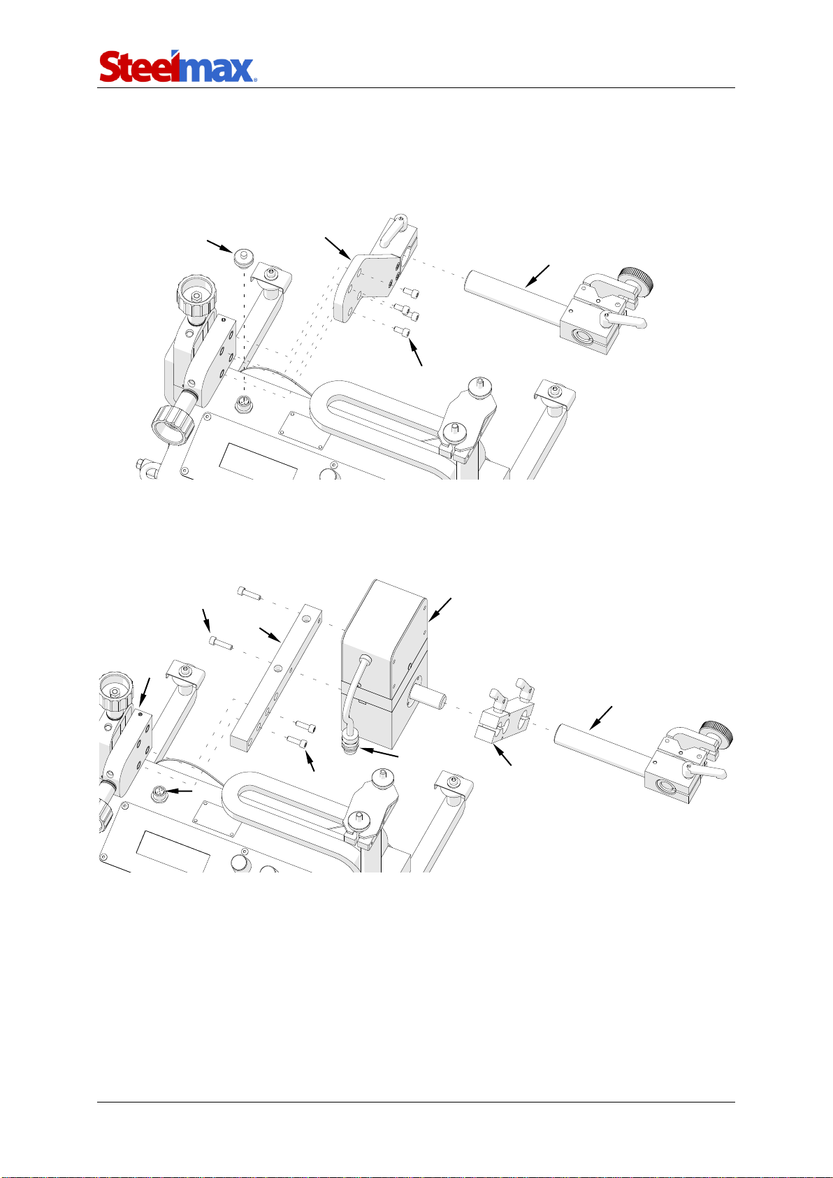
3.8. Using oscillator (option)
3.8.1. Installing
Install the oscillator in the shown sequence.
•Remove the torch holder (1).
•Use the 4 mm hex wrench to remove the screws (2) and the torch holder plate (3).
•Remove the cap (4).
•Attach the arm (5)to the oscillator (6).
•Use two screws M5x20 (7) to attach the oscillator (6) to the bracket (8).
•Use two screws M5x16 (9) to connect the bracket (8) to the cross slide (10).
•Put the oscillator plug (11) into the oscillation socket (12).
•Attach the torch holder (13) to the oscillator arm (5).
8
6
7
8
9
12
10
6
11
5
13
4
3
2
1

ARC Runner
ARC Runner Operator’s Manual
18
3.8.2. Welding with oscillation
After you connect the oscillator to the welding carriage, several new settings will
show in the menu (Tab. 2). Welding with oscillation is done in the standard manner,
but the weld form a shape similar to the shape shown in Fig. 7 instead of the straight
line from Fig. 6.
Parameter
Value
Description
0–100%
[step: 10% or 1%]
Relative amplitude of the oscilla-
tion.
0–100%
[step: 10% or 1%]
Relative speed of the oscillation.
The higher the speed, the shorter
the oscillation period.
0–5 s
[step: 1 or 0.1]
Dwell time in the top position of
the oscillation.
0–5 s
[step: 1 or 0.1]
Dwell time in the bottom position
of the oscillation.
YES
NO
With YES, you cannot change
dwell times during welding.
Tab. 2. Additional settings available with connected oscillator
Fig. 3.Graphic description of the oscillation parameters from Tab. 2
Weld start
Weld end
1 /
ARC Runner
ARC Runner Operator’s Manual
19
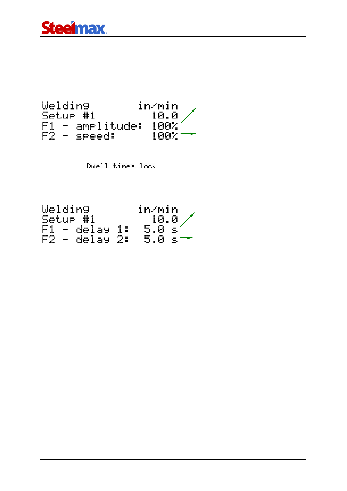
3.8.3. Operating
The carriage with connected oscillator is operated similarly to operating without the
oscillator. During welding with the oscillator, the menu from Fig. 8 shows on the
display.
Fig. 4.Menu shown during welding with the oscillator
If you set to YES, nothing happens when you press the
knob F1 or F2 during work. If you set the parameter to NO, the delay parameters
show on the display and you can adjust them online (Fig. 9).
Fig. 5.Menu for changing the oscillator dwell times
Rotate the knob F1 to change the
oscillation amplitude by 1%.
Rotate the knob F2 to change the
oscillation speed by 1%.
Rotate the knob F2 to change the delay 2
by 0.1 s. Press the F2 to switch from
showing delay 2 to oscillation speed.
Rotate the knob F1 to change the delay 1
by 0.1 s. Press the F1 to switch from
showing delay 1 to oscillation amplitude.

ARC Runner
ARC Runner Operator’s Manual
20
3.9. Troubleshooting
Problem
Cause
Solution
Dark LCD display after power-
ing.
Malfunction of the power
cord, power switch, power
supply, or controller.
Contact service center for
check and repair.
Errors on the LCD display.
Values cannot be read.
Malfunction of the display
or power supply unit.
Contact service center for
check and repair.
Carriage reached an
obstacle at the front.
Remove the obstacle that
blocks the carriage or choose
the opposite travel direction.
Carriage reached an
obstacle at the rear.
Remove the obstacle that
blocks the carriage or choose
the opposite travel direction.
Too fast switching between
left and right travel direc-
tion.
Set the travel direction switch
to ‘O’.
Travel direction switch not
set to ‘O’ when powering.
Set the travel direction switch
to ‘O’.
Shown during travel indi-
cates a malfunction.
Contact service center for
check and repair.
Other manuals for ARC Runner
1
Table of contents
Other SteelMax Welding System manuals


Popular Welding System manuals by other brands

Lincoln Electric
Lincoln Electric POWERPLUS 1000HD Operator's manual

Lincoln Electric
Lincoln Electric BULLDOG IM10074 Operator's manual

Miller
Miller ADI 253 instruction manual

PlasmaPart
PlasmaPart Cut 45CI Eclipse Operation & safety manual

Jasic
Jasic EVO 2.0 EM-200CT Operator's manual

Century
Century INVERTER ARC 230 Operator's manual


