Toolex 597076 User manual

!1!/!16!
!
!
! 1!
!
!
!

!2!/!16!
!
!
! 2!
!
!
!
SAVE THIS MANUAL
Keep this manual for the safety
warnings and precautions, assembly,
operating, inspection, maintenance and
cleaning procedures. Write the product’s
serial number in the back of the manual
near the assembly diagram (or month and
year of purchase if product has no
number). Keep this manual and the receipt
in a safe and dry place for future
reference.
IMPROTANT SAFETY INFORMATION
In this manual, on the labeling, and all
other information provided with this
product:
This is the safety alert symbol. It is
used to alert you to potential personal
injury hazards. Obey all safety
messages that follow this symbol to
avoid possible injury or death.
DANGER indicates a hazardous
situation which, if not avoided, will
result in death or serious injury.
WARNING: WARNING indicates a
hazardous situation which, if not
avoided, could result in death or
serious injury.
CAUTION: CAUTION, used with
the safety alert symbol, indicates a
hazardous situation which, if not
avoided, could result in minor or
moderate injury.
NOTICE:NOTICE is used to
address practices not related to
personal injury.
SAFETY WARNINGS AND
PRECAUTIONS
WARNING: When using tool, basic safety
precautions should always be followed to
reduce the risk of personal injury and
damage to equipment.
Read all instructions before using this
tool!
Work Area Precautions
1. Keep your work area clean and well
lit. Cluttered benches and dark areas
invite accidents.
2. Do not operate power tools in
explosive atmospheres, such as in
the presence of flammable liquids,
gases, or dust. Power tools create
sparks which may ignite the dust or
fumes.
3. Keep bystanders, children, and
visitors away while operating a
power tool. Distractions can cause
you to lose control. Protect others in
the work area from debris such as
chips and sparks. Provide barriers or
shields as needed.
WARNING!+
+
READ+AND+UNDERSTAND+ALL+INSTRUCTIONS+
Failure+to+follow+all+instructions+listed+below+may+result+in+
electric+shock,+fire,+and/or+serious+injury.+
SAVE+THESE+INSTRUCTIONS+

!3!/!16!
!
!
! 3!
!
!
!
Electrical Safety
1. Grounded tools must be plugged
into an outlet properly installed and
grounded in accordance with all
codes and ordinances. Never
remove the grounding prong or
modify the plug in any way. Do not
use any adapter plugs. Check with
a qualified electrician if you are in
doubt whether the outlet is properly
grounded. If the tool should
electrically malfunction or break down,
grounding provides a low resistance
path to carry electricity away from the
user.
2. Double insulated tools are
equipped with a polarized plug (one
blade is wider than the other). This
plug will fit in a polarized outlet
only one way. If the plug does not
fit fully in the outlet, reverse the
plug. If it still does not fit, contact a
qualified electrician to install a
polarized outlet. Do not change the
plug in any way. Double insulation
eliminates the need for the three wire
grounded power cord and grounded
power supply system.
3. Avoid body contact with grounded
surfaces such as pipes, radiators,
ranges, and refrigerators. There is
an increased risk of electric shock if
your body is grounded.
4. Do not expose power tools to rain
or wet conditions. Water entering a
power tool will increase the risk of
electric shock.
5. Do not abuse the Power Cord.
Never use the Power Cord to carry
the tool or pull the Plug from an
outlet. Keep the Power Cord away
from heat, oil, sharp edges, or
moving parts. Replace damaged
Power Cords immediately.
Damaged Power Cords increase the
risk of electric shock.
6. When operating a power tool
outside, sue an outdoor extension
cord marker “W-A” or “W”. These
extension cords are rated for outdoor
use, and reduce the risk of electric
shock.
Personal Safety
1. Stay alert. Watch what you are
doing, and use common sense
when operating a power tool. Do
not use a power tool while tired or
under the influence of drugs,
alcohol, or medication. A moment of
inattention while operating power tools
may result in serious personal injury.
2. Dress properly. Do not wear loose
clothing or jewelry. Contain long
hair. Keep your hair, clothing, and
gloves away from moving parts.
Loose clothes, jewelry, or long hair
can be caught in moving parts.
3. Avoid accidental staring. Be sure
the Power Switch is off before
plugging in. Carrying power tools
with your finger on the Power Switch,
or plugging in power tools with the
Power Switch on, invites accidents.
4. Remove adjusting keys or
wrenches before turning the power
tool on. A wrench or a key that is left
attached to a rotating part of the power
tool may result in personal injury.
5. Do not overreach. Keep proper
footing and balance at all times.
Proper footing and balance enables
better control of the power tool in
unexpected situations.
6. Use safety equipment. Always wear
eye protection. Dust mask, non-skid
safety shoes, hard hat, or hearing

!4!/!16!
!
!
! 4!
!
!
!
protection must be used for
appropriate conditions.
Tool Use and Care
1. Use clamps (not included) or other
practical ways to secure and
support the workpiece to a stable
platform. Holding the work piece by
hand to against your body is unstable
and may lead to loss of control.
2. Do not force the tool. Use the
correct tool for your application.
The correct tool will do the job better
and safer at the rate for which it is
designed.
3. Do not use the power tool if the
Power Switch does not turn it on or
off. Any tool that cannot be controlled
with the Power Switch is dangerous
and must be replaced.
4. Disconnect the Power Cord Plug
from the power source before
making any adjustments, changing
accessories, or storing the tool.
Such preventive safety measures
reduce the risk of starting the tool
accidentally.
5. Store idle tools out of reach of
children and other untrained
persons. Tools are dangerous in the
hands of untrained users.
6. Maintain tools with care. Keep
cutting tools maintained and clean.
Properly maintained tools are less
likely to bind and are easier to control.
Do not use a damaged tool. Tag
damaged tools “Do not use” until
repaired
7. Check for misalignment or binding
of moving parts, breakage of parts,
and any other condition that may
affect the tool’s operation. If
damaged, have the tool serviced
before using. Many accidents are
caused by poorly maintained tools.
8. Use only accessories that are
recommended by the manufacturer
for your model. Accessories that may
be suitable for one tool may become
hazardous when used on another tool.
Service
1. Tool service must be performed only
by qualified repair personnel. Service
or maintenance performed by
unqualified personnel could result in a
risk of injury.
2. When servicing a tool, use only
identical replacement parts. Use of
unauthorized parts or failure to follow
maintenance instructions may create a
risk of electric shock or injury.
SPECIFIC SAFETY RULES
1. Maintain labels and nameplates on
the tool. These carry important
information. If unreadable or missing,
contact TOOLEX INDUSTRIAL for a
replacement.
2. Always wear the approved safety
impact eye goggles and heavy work
gloves when suing the tool. Using
personal safety devices reduce the
risk for injury. Safety impact eye
goggles and heavy work gloves are
available from Harbor Freight Tools.
3. Maintain a safe working
environment. Keep the work area
well lit. Make sure there is adequate
surrounding workspace. Always keep
the work area free of obstructions,
grease, oil, trash, and other debris. Do
not use a power tool in areas near
flammable chemicals, dusts, and
vapors. Do not use this product in a
damp or wet location.

!5!/!16!
!
!
! 5!
!
!
!
4. Avoid unintentional starting. Make
sure you are prepared to begin work
before turning on the tool.
5. Never leave the tool unattended
when it is plugged into an electrical
outlet. Turn off the tool, and unplug it
from its electrical outlet before leaving.
6. Always unplug the tool from its
electrical outlet before performing
and inspection, maintenance, or
cleaning procedures.
7. Prevent eye injury and burns.
Wearing and using the approved
personal safety clothing and safety
devices reduce the risk for injury.
a. Wear the approved safety impact
eye goggles with a welding helmet
featuring at least a number 10
shade lens rating.
b. Leather leggings, fire resistant
shoes or boots should be worn
when using this product. Do not
wear pants with cuffs, shirts with
open pockets, or any clothing that
can catch and hold molten metal
or sparks.
c. Keep clothing free of grease, oil,
solvents, or any flammable
substances. Wear dry, insulating
gloves and protective clothing.
d. Wear an approved head covering
to protect the head and neck. Use
aprons, cape, sleeves, shoulder
covers, and bibs designed and
approved for welding and cutting
procedures.
e. When welding/cutting overhead or
in confined spaces, wear flame
resistant ear plugs or ear muffs to
keep sparks out of ears.
8. Prevent accidental fires. Remove
any combustible material from the
work area.
a. When possible, move the work to
a location well away from
combustible; protect the
combustibles with a cover made of
fire resistant material.
b. Remove or make safe all
combustible materials for a radius
of 35 feet (10 meters) around the
work area. Use a fire resistant
material to cover or block all open
doorways, windows, cracks, and
other openings.
c. Enclose the work area with
portable fire resistant screens.
Protect combustible walls, ceilings,
floors, etc., from sparks and heat
with fire resistant covers.
d. If working on a metal wall, ceiling,
etc., prevent ignition of
combustibles on the other side by
mobbing the combustibles to a
safe location. If relocation of
combustibles is not possible,
designate someone to serve as a
fire watch, equipped with a fire
extinguisher, during the welding
process and for at least one half
hour after the welding is
completed.
e. Do not weld or cut on materials
having a combustible coating or
combustible internal structure, as
in walls or ceilings, without an
approved method for eliminating
the hazard.
f. Do not dispose of hot slag in
containers holding combustible
materials. Keep a fire extinguisher
nearby and know how to use it.
g. After welding or cutting, make a
thorough examination for evidence
of fire. Be aware that easily visible
smoke or flame may not be
present for some time after the fire
has started. Do not weld or cut in

!6!/!16!
!
!
! 6!
!
!
!
atmospheres containing
h. Dangerously reactive or
flammable gases, vapors, liquids,
and dust.
i. Provide adequate ventilation in
work areas to prevent
accumulation of flammable gases,
vapors, and dust. Do not apply
heat to a container that has held
an unknown substance or a
combustible material whose
contents, when heated, can
produce flammable or explosive
vapors. Clean and purge
containers before applying heat.
Vent closed containers, including
castings, before preheating,
welding, or cutting.
9. Avoid overexposure to fumes and
gases. Always keep your head out of
the fumes. Do not breathe the fumes.
Use enough ventilation or exhaust, or
both, to keep fumes and gases from
your breathing zone and general area.
ℓWhere ventilation is questionable,
have a qualified technician take
an air sampling to determine the
need for corrective measures.
Use mechanical ventilation to
improve air quality. If engineering
controls are not feasible, use an
approved respirator.
ℓWork in a confined area only if it
is well ventilated, or while
wearing an air-supplied
respirator.
ℓFollow OSHA guidelines for
Permissible Exposure Limits
(PEL’s) for various fumes and
gases.
ℓFollow the American Conference
of Governmental Industrial
Hygienists recommendations for
Threshold Limit Values (TLV’s)
for fumes and gases.
ℓHave a recognized specialist in
Industrial Hygiene or
Environmental Services check
the operation and air quality and
make recommendations for the
specific welding or cutting
situation.
10. Always keep hoses away from
welding/cutting spot. Examine all
hoses and cables for cuts, burns, or
worn areas before each use. If any
damaged areas are found, replace the
hoses or cables immediately.
11. Read and understand all
instructions and safety precautions
as outlined in the manufacturer’s
WARNING+
INHALATION+HAZARD:+Welding+and+Plasma+Cutting+
Produce+
TOXIC+FUMES.+
Exposure! to! welding! or! cutting! exhaust! fumes! can!
increase!the!risk!of!developing!certain!cancers,!such!
as!cancer!of!the!larynx!and!lung!cancer.!Also,!some!
diseases!that!may!be!linked!to!exposure!to!welding!
or!plasma!cutting!exhaust!fumes!are:!
a. Early!onset!of!Parkinson’s!Disease!
b. Heart!disease!
c. Ulcers!
d. Damage!to!the!reproductive!organs! !
e. Inflammation!of!the!small!intestine!or!stomach! !
f. Kidney!damage!
g. Respiratory! diseases! such! as! emphysema,!
bronchitis,!or!pneumonia!
Use! natural! or! forced! air! ventilation! and! wear! a!
respirator!approved!by!NIOSH!to!protect!against!the!
fumes!produced!to!reduce!the!risk!of!developing!the!
above!illnesses.!

!7!/!16!
!
!
! 7!
!
!
!
Manual for the material you will
weld or cut.
12. Proper cylinder care. Secure
cylinders to a cart, wall, or post, to
prevent them from falling. All cylinders
should be used and stored in an
upright position. Never drop or strike a
cylinder. Do not use cylinders that
have been dented. Cylinder caps
should be used when moving or
storing cylinders. Empty cylinders
should be kept in specified areas and
clearly marked “empty.”
13. Never use oil or grease on any
inlet connector, outlet connector,
or cylinder valves.
14. Use only supplied Torch on this
Inverter Air Plasma Cutter. Using
components from other systems may
cause personal injury and damage
components within.
15. People with pacemakers should
consult their physician(s) before using
this product. Electromagnetic fields in
close proximity to a heart pacemaker
could cause interference to, or failure
of the pacemaker.
16. USE PROPER EXTENSION
CORD.
Make sure your extension cord is in
good condition. When using an
extension cord, be sure to sue one
heavy enough to carry the current your
product will draw. An undersized cord
will cause a drop in line voltage
resulting in loss of power and
overheating. A 50 foot extension cord
must be at least 12 gauges in diameter,
and a 100 foot extension cord must be
at least 10 gauges in diameter. If in
doubt, use the next heavier gauge.
The smaller the gauge number, the
heavier the cord.

!8!/!16!
!
!
! 8!
!
!
!
SPECIFICATIONS
Note:
A Amp.
I2 Rated welding current
DC
V Voltage
U2 Rated input voltage
AC
U0 No-load voltage
X Rated duty cycle
TIG welding
U1 Rated input voltage
S1 KVA
Manual Arc welding
I1 Input current
IP Protection degree
Single phase, AC/DC power supply
I1eff
OFF Connected
power supply under very dangerous situation
I1max
ON Disconnected
IP21S cover protection degree
Model
Parameters
ANVAN TIG 200
Rated Input Voltage (V)
1PH ~ 220V±15% ( 50/60HZ)
Rated Input Power (KVA)
6
Rated Input Current (A)
28
Related output (V)
200A/18 V
Output Current Range (A)
10 ~ 200
Duty Cycle (%)
35% 200A
60% 153A
100% 118A
No Load Voltage (V)
66
Efficiency (%)
85
Protection Class
IP21S
Dimension (mm)
367*185*320
Insulation Grade
F
Weight (kg)
8.9
1 2 3 4 5 6 7 8
A
B
C
D
87654321
D
C
B
A
Title
Number Re visionSize
A3
Date: 24-Sep-2004 Sheet of
File: D: \技术资料\焊接电源符号.ddb Drawn By:
S
1 2 3 4
A
B
C
D
4321
D
C
B
ATitle
Number RevisionSize
A4
Date: 13-Aug-2002 Sheet of
File: E :\Program Files\Design Explorer 99\Examples\∫∏Ω”µÁ‘¥∑˚∫≈.ddbDrawn By:
1 2 3 4 5 6 7 8
A
B
C
D
87654321
D
C
B
A
Title
Number Revisio nSize
A3
Date: 2 4-Sep-2004 Sheet of
File: D: \技术资料\焊接电源符号.ddb Drawn By:
~+
1 2 3 4 5 6 7 8
A
B
C
D
87654321
D
C
B
A
Title
Number RevisionSize
A3
Date: 24-Sep-2004 Sheet of
File: D:\ 技术资料\焊接电源符号.ddb DrawnBy:
!9!/!16!
!!
!
!9!
!
!
!
Duty Cycle
Duty Cycle is the equipment
specifications which defines the number of
minutes within a 10 minute period that a
piece of equipment can safely operate.
ADVAN (IGBT module) TIG machines
with 60% duty cycle at maximum
welding output,which means that it
continuously operates for 6 minutes at
maximum output during a 10 minute
period.
CAUTION: Failure to observe the duty
cycle limitations of this TIG MACHINE can
easily damage this equipment, and will
void warranty.
UNPACKING
When unpacking, checks to make sure the
following parts are included.
Inverter welding machine with
TIG torch with Power Cord
Ground cable with Clamp
Back-up Accessories for torch
If any parts are missing or broken, please
call EACO ELECTRIC at the number on
the cover of this manual.
Preparing Your Work Area
1. You must have a sturdy work table
that is open below the area you are
welding. Molten slag will be blown
through the work metal, and must be
able to fall away freely
2. Your work table must allow the work
metal to be firmly clamped to prevent it
accidentally falling or moving.
3. The floor and surrounding area of your
work site must not be flammable. A
clean cement floor is recommended.
The cutting process will eject molten
metal slag onto the floor, and it will
scatter for 8-10 feet or more in any
direction. Have an adequate fire
extinguisher available if needed.
ASSEMBLY
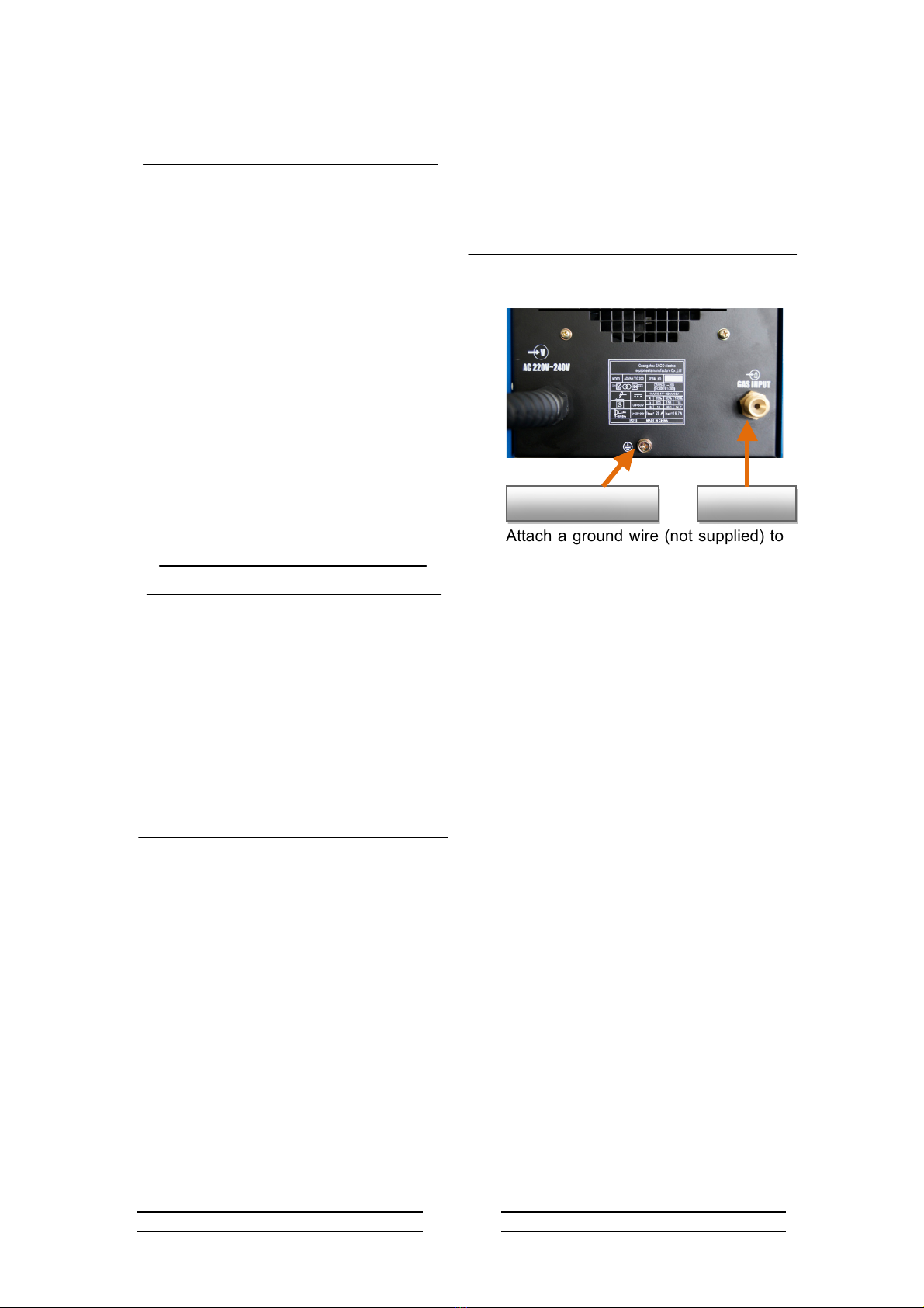
Grounding the tool and attach air
supply:
1. Attach a ground wire (not supplied) to
the screw in the lower the back of the
machine. Connect the gas air inlet to
your supply Argon by one air hose (not
supplied). And remember to fasten it
with coupling.
WARNING: Only use dry Argon as the
gas in this tool. Use of any other gas,
such as oxygen, acetylene, etc. may
cause explosion.
Ground!screw! !
Gas!inlet!
!10!/!16!
!
!
!10!
!
!
!
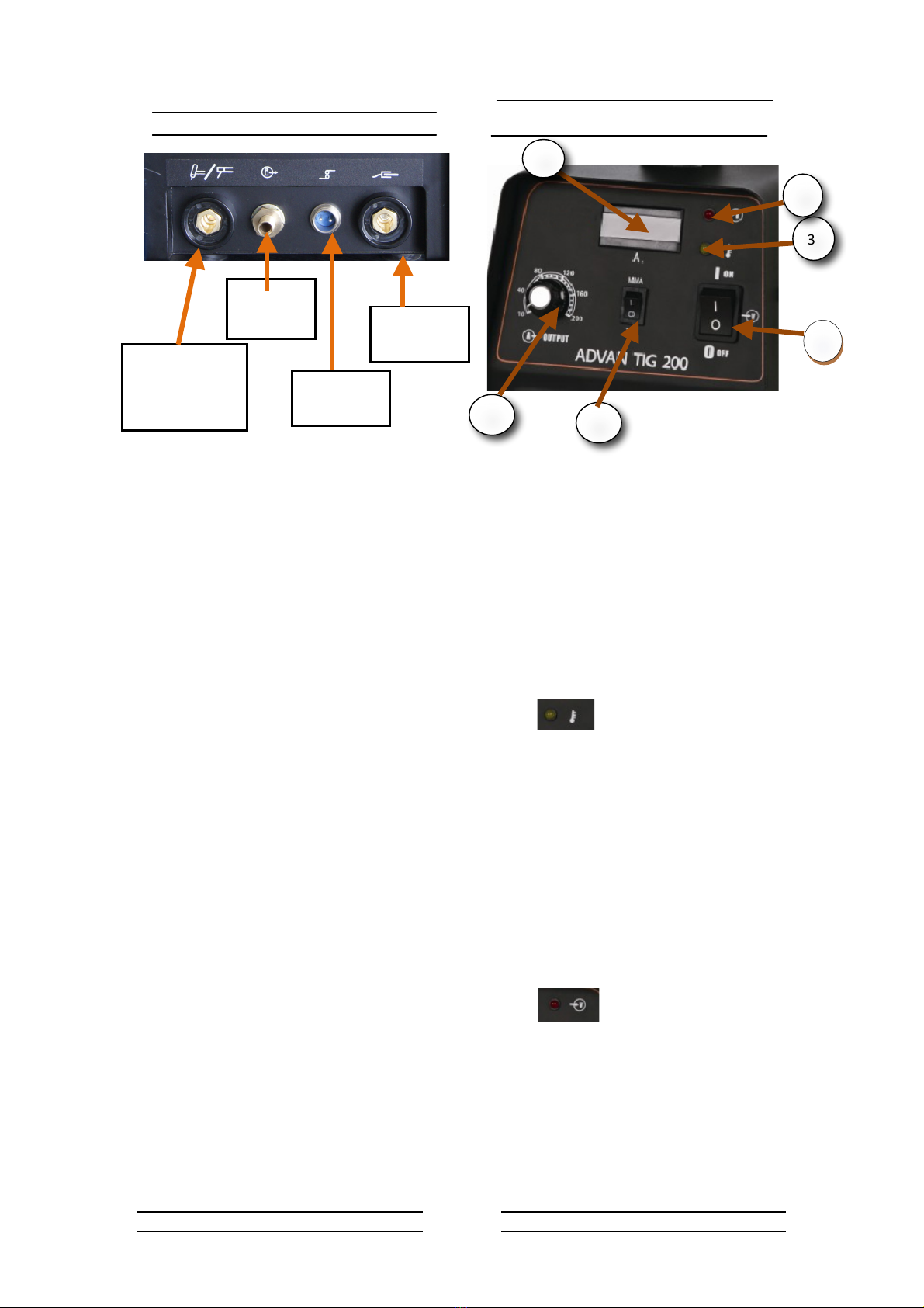
TIG Torch Connector and Instruction
1. TIG torch cable socket: Connect
TIG! torch! control (1B) of the TIG torch
left to this socket. (1).
2. Gas outlet: Screw the gas outlet hose
(2B) of the torch to this connector;
3. TIG torch cable socket :Connect the
TIG cable plug (3B) to this aviation
socket(3);
4. Ground socket: Plug!ground! cable! to!
this!socket.
Front Panel
The front panel of MAX TIG 160 and MAX
TIG 200 is absolutely the same; we take
MAX TIG 200 for example hereby.
1. Power Switch. Up is ON, down is
OFF.
2. Digital Amps Meter. Shows actual
welding current, which will vary
during operation.
3. “” Thermal Overload
Indicator Lamp. This light will come
on, and the device will shut down if
the tool becomes overheated. Stop
trying to use the cutter while leaving
the power switch onto allow the
cooling fan to operate, and the lamp
will turn off automatically when the
machine cools down. Please pay
attention to the Rated Duty Cycle
discussed on page 2.
4. “ ” Working Indicator
Light. It will be on during welding
operation.
5. Power Supply Controller: It can
adjust welding current.
6. Mode selector :Select MMA welding
or TIG welding:
Gas!
outlet!(2)!
Ground!
socket!(4)!
TIG! torch!
control! socket!
(1)!
Cable!
socket!(3)!
1!
2!
3!
4!
5!
6!

!11!/!16!
!
!
!11!
!
!
!
“ ” means MMA welding,
when you chose this welding mode,
please plug the welding plug with
cable to the TIG control socket (refer
to page 9, (1)).
“ ” means TIG welding, when
this TIG welding mode is selected,
please plug the TIG torch control cable
in to TIG control socket (refer to page
9, (1)).
OPERATION
Note: Before beginning, please read and
understand all the safety precautions
staring on page 1 and especially the
section “Specific Safety Rules” starting on
page 3.
1. Put the metal to be welded on the
metal weeding-cutting table. Ensure
the metals to be welded are clean, so
good welding efficiency can be
promised.
2. Place the TIG welding unit no closer
than six feet from the workpicece to be
welded
3. Connect the TIG torch control, cable
plug, and gas outlet hose as shown on
page 9. Twist to lock in place.
4. Plug in the Grounding Cable into the
Ground Connector on the lower left of
the unit front. Twist to lock.
5. Securely place the clamping end of
the Grounding Cable Clamp to a part
of the workpiece or metal table that is
clean of paint, oil, or dirt. Clamp as
close as possible to the workpiece
without damaging the cable during
welding.
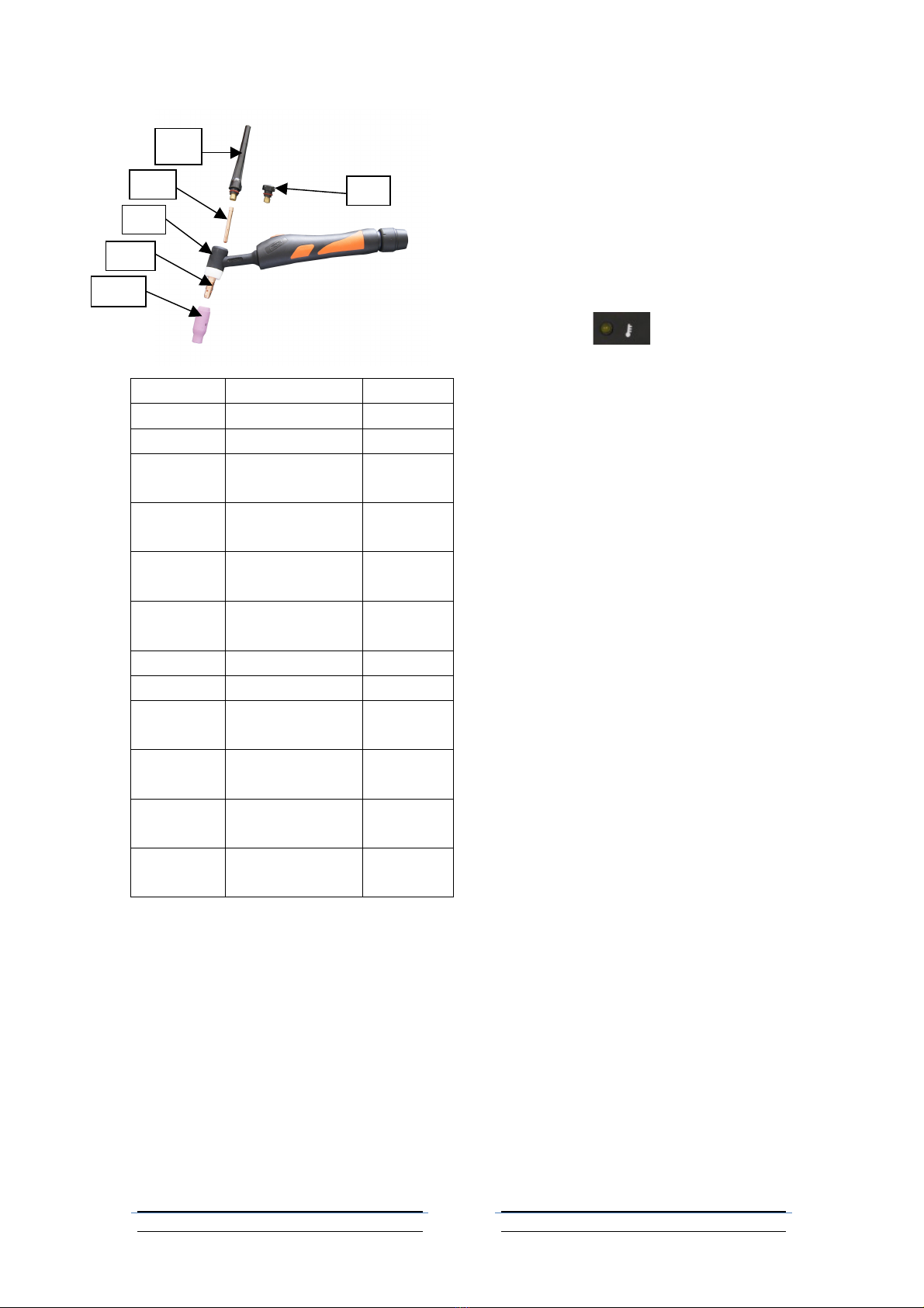
6. Assemble the desired accessories and
rod inside the tip of the TIG Torch
handle.
a. Unscrew the Ceramic Nozzle (6A)
on the Torch Handle (4A).
b. Unscrew the Collect Housing (5A).
c. Place a 5/32” prepared tungsten
welding rod (not included) into the
torch.
d. Screw the Collect Housing and
Ceramic Nozzle back onto the
Torch.
7. Connect a hose and coupling from
the gas regulator on an Argon gas
tank (none included) to the Argon
Gas Inlet on the back of the unit.
Follow the gas cylinder
manufacturer’s instructions for set-up
and use.
8. Verify that the Power Switch is in the
off position, then plug the 220V~line
cord plug into an appropriate
220V~outlet.
9. When everything is in place for
welding, press the Power Switch UP
to the ON position. The Power Light”
will illuminate, but the
Torch is not yet energized.
10. Press the torch and orient yourself to
one side of the area to be welded,
and move the Welding Helmet Face
Shield (not included, see page 4 item
7) over your eyes.
11. Caution: The Torch handle is now
energized. Be careful not touch
anything else with the Torch except
the workpiece to be welded.
DANGER! To prevent serious injury
and death: The TIG Welder will
immediately turn on when the
trigger is held down.
!12!/!16!
!
!
!12!
!
!
!
Part
Description
Qty
1A
Long Back Cap
1
2A
Short Back Cap
1
3A1
Collet 1/16”
(1.6mm)
1
3A2
Collet 2/25”
(2.0mm)
1
3A3
Collet 3/32”
(2.4mm)
1
3A4
Collet 1/8”
(3.2mm)
1
4A
Torch Handle
1
5A
Collets Housing
1
6A1
Ceramic Nozzle
size 4; 10N50
1
6A2
Ceramic Nozzle
size 5; 10N49
1
6A3
Ceramic Nozzle
size 6; 10N48
1
6A4
Ceramic Nozzle
size 7; 10N47
1
(Refer to parts diagram above for Torch
Handle components.) Direct torch away
from people and flammables, while you
press (and hold) the Torch Handle Trigger
(2A) to energize the Torch Electrode (4A).
12. Hold the Trigger down and tilt the
torch forward. Keep a constant
distance between the torch and the
workpiece but do not contact it.
13. Stroke the workpiece lightly to ignite
the arc. Do not strike like a match.
Never tap the electrode wire to ignite
the arc; it will damage the electrode.
14. When the arc ignites, tilt the
electrode forward and hold it near
the workpiece.
15. If too much current is drawn from the
welder; the Thermal Overload
protector will activate, the
Overload indicator will light, and the
welder will turn off until it cools down.
It will automatically reset.
DANGER! To prevent serious injury
and death: If the operator is not
holding the Torch, it must be sitting on
a nonconductive, nonflammable
surface.
Arc (stick) Connection
1. Connect the Electrode Clamp and
Cable to the torch control connector
(as 7 shown on page 9 and twist to
lock in place.
2. Plug the cable of the Grounding
Clamp into the DC ground connector
and secure the clamp to a clean,
exposed metal part of the workpiece.
3. Place the metal portion of the
welding rod inside the jaws of the
Electrode Clamp. Welding rod types
vary for welding different metals.
When finished welding
a. Release the Torch handle trigger
and lift the Torch handle from the
workpiece,
b. Press the Power Switch to the Off
(O) position.
c. Set the Torch handle down on the
metal workbench,
d. Turn the air supply off,
e. Unplug the line cord from the
1A!
2A!
3A!
4A!
5A!
6A!
!13!/!16!
!
!
!13!
!
!
!
electrical outlet.
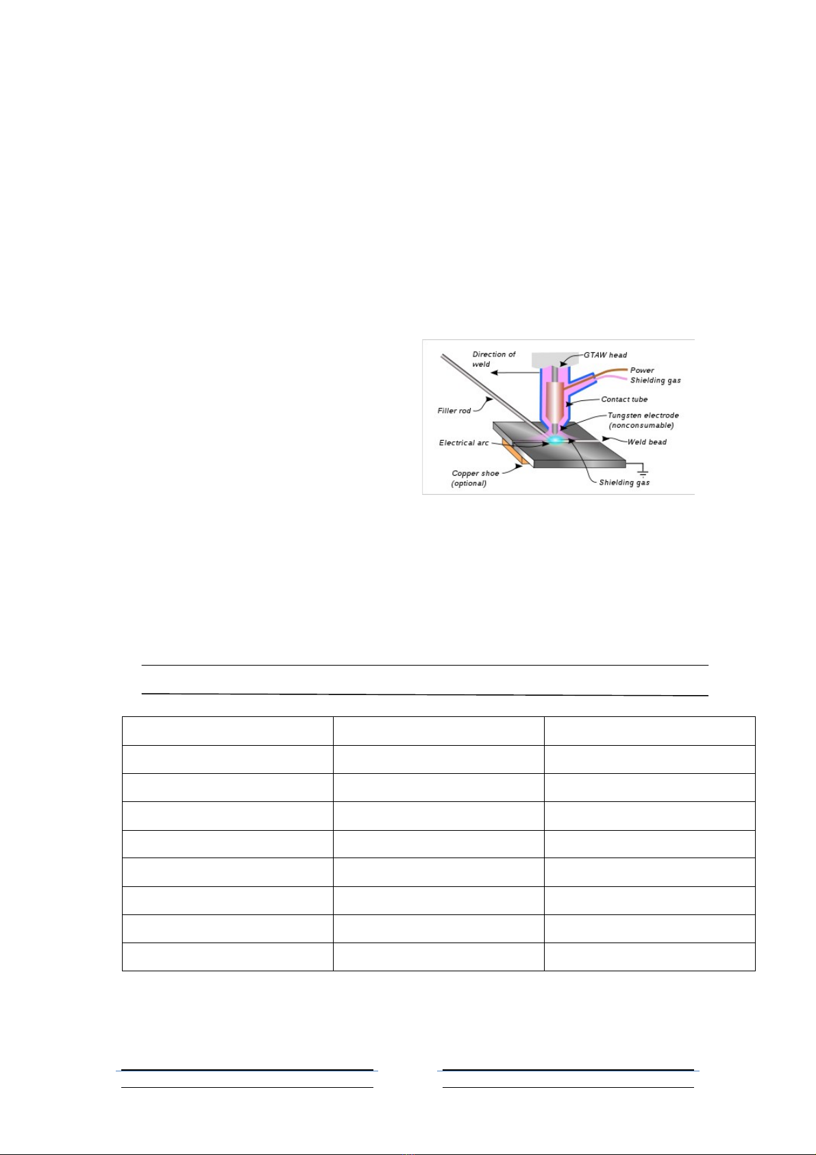
Tungsten Inert Gas (TIG) Welding
Gas tungsten arc welding (GTAW),
also known as tungsten inert gas (TIG)
welding, is an arc welding process that
uses a no consumable tungsten electrode
to produce the weld. The weld area is
protected from atmospheric contamination
by a shielding gas (usually an inert gas
such as argon), and a filler metal is
normally used, though some welds, known
as autogenously welds, do not require it. A
constant-current welding power supply
produces energy which is conducted
across the arc through a column of highly
ionized gas and metal vapors known as
plasma. TAW is most commonly used to
weld thin sections of stainless steel and
non-ferrous metals such as aluminum,
magnesium, and copper alloys. The
process grants the operator greater
control over the weld than competing
procedures such as shielded metal arc
welding and gas metal arc welding,
allowing for stronger, higher quality welds.
However, GTAW is comparatively more
complex and difficult to master, and
furthermore, it is significantly slower than
most other welding techniques. A related
process, plasma arc welding, uses a
slightly different welding torch to create a
more focused welding arc and as a result
is often automated.
TIPS FOR TIG WELDING
Welding current(A)
Tungsten diameter(mm)
Argon flux(L/min)
5~15
0.5
3~7
10~65
1.0
4~8
55~120
1.6
6~9
85~150
2.0
6~10
120~200
2.4
7~10
200~320
3.2
10~15
320~400
4.0
12~20
400~640
4.8
15~25

!14!/!16!
!
!
!14!
!
!
!
4. STAINLESS STEEL(SUS304)WELDING PARAMETER:
Steel
thickness
Tungsten
diameter
Wire
diameter
Welding
current
Argon flux
Clearance
size
Clearance
form
(mm)
(mm)
(mm)
(A)
(L/min)
(mm)
0.6
1.0~1.6
0~1.0
15~30
4~5
1
a、b
1.0
1.0~1.6
0~1.6
25~30
4~7
1
a、b
1.5
1.0~1.6
0~1.6
50~70
6~9
1
b
2.5
1.6~2.4
1.6~2.4
65~95
6~9
1
b
3.0
1.6~2.4
1.6~2.4
90~120
7~10
1~2
b、c
4.0
2.4
1.6~2.4
110~150
10~15
2~3
c、d
5.0
2.4~3.2
2.4~3.2
120~180
10~15
2~3
c、d
6.0
2.4~3.2
2.4~3.2
150~200
10~15
3~4
c、d
8.0
3.2~4.0
3.2~4.0
160~220
12~18
4~5
d
12.0
3.2~4.0
3.2~4.0
180~240
12~18
6~8
d
5. ALUMINUM WELDING PARAMETER
Aluminum
thickness
Tungsten
diameter
Wire
diameter
Welding
current
Argon flux
Clearance
size
Clearance
form
(mm)
(mm)
(mm)
(A)
(L/min)
(mm)
0.6
1.0~1.6
0~1.0
25~40
4~5
1
a、b
1.0
1.0~1.6
0~1.6
40~60
4~7
1
a、b
1.5
1.0~1.6
0~1.6
60~90
6~9
1
b
2.5
1.6~2.4
1.6~2.4
80~120
6~9
1
b
3.0
1.6~2.4
1.6~2.4
100~160
7~10
1~2
b、c
4.0
2.4
1.6~2.4
130~200
10~15
2~3
c、d
5.0
2.4~3.2
2.4~3.2
150~250
10~15
2~3
c、d
6.0
2.4~3.2
2.4~3.2
200~280
10~15
3~4
c、d
8.0
3.2~4.0
3.2~4.0
200~300
12~18
4~5
d
(c) (d)
(a) (b)

!15!/!16!
!
!
!15!
!
!
!
CLEARANCE FORM
MAINTENANCE
WARNING! Make sure the Power
Switch of the welder is in its “OFF”
position and that the tool is unplugged
from the electrical outlet before
performing any inspection,
maintenance, or cleaning procedures.
1. Before each use, inspect the general
condition of the Welder. Check for
loose cable connections, misalignment
or binding of the fan, cracked or
broken parts, damaged electrical
wiring, and any other condition that
may affect its safe operation. If
abnormal noise or vibration occurs,
have the problem corrected before
further use. Do not use damaged
equipment.
2. Periodically recheck all nuts, bolts,
and screws for tightness.
3. Periodically blow the dust from the
cooling vents with compressed air.
4. Verify that the cooling fan is
operational before cutting.
5. If the unit repeatedly shuts down from
thermal overload, stop all use. Have
the welder inspected and repaired by
a qualified service technician.
6. Store the welder and accessories in a
clean and dry location.
7. Periodically disassemble and clean
the Torch Head components with steel
wool. Replace burnt, cracked,
distorted, or coated components,
Refer to the assembly drawing on
page 11.
8. To gain access to the internal
components of the unit, remove
screws from Main Body Cover. The
home user is strongly advised not to
remove the tool covers and not to
attempt any electronic repairs. Any
repairs must be completed by a
qualified technician. Opening the tool
will void any warranties, and may
result in damage to equipment or
possible personal injury. Don’t do it.
9. On a daily basis check for any of the
following problems: If any are found,
take the tool to a qualified repair
technician.
a. Abnormal vibration, sound or
smell.
b. Abnormal heating at any cable
connection.
c. Then fan does not work properly.
d. Any switch or control does not
work properly.
e. Any damage to cables.

!16!/!16!
!
!
!16!
!
!
!
TROUBLESHOOTING
IMPORTANT!
Be CERTAIN to shut off the Welder and disconnect it from power and air
before adjusting, cleaning, or repairing the unit. A technician should discharge all
capacitors before performing and internal procedures.
Problem
Possible Causes
Likely Solutions
Tool will not start
1. No power at outlet.
2. Cord not connected.
3. Line voltage incorrect.
1. Check power at outlet.
2. Check that cord is
plugged in.
3. Make sure the welder
is plugged into a
230V electrical outlet.
No weld output with ready
light on
1. Weld cable loose.
2. Bad work clamp to
workpiece connection.
1. Tighten weld cable
connection at welder
2. Make sure the area
where the clamp is
attached is clean,
exposed metal; free of
dirt, paint and oil.
No weld output; high
temperature light on
1. Welder overheated.
2. Duty cycle or amps too
high.
3. Airflow is blocked.
1. Allow unit to cool with
the fan on.
2. Reduce duty cycle or
amps.
3. Clean vents and fan out
with compressed air.
Erratic or improper arc or
welding output
1. Bad weld connections.
2. Polarity incorrect.
3. Workpiece painted or
dirty.
4. Ceramic Nozzle
obstructed by welding
spatter.
1. Clean and tighten weld
connections.
2. Connect polarity
correctly.
3. Clean workpiece
thoroughly.
4. Clean or replace
nozzle.
Fan not operating
1. Fan blocked/dirty.
2. Fan broken.
1. Remove obstruction and
clean with compressed
air.
2. Have the fan replaced
by a qualified service
technician.
Main Supply Fuse
shuts off frequently
Circuit Breaker rating is too
low.
Install a circuit breaker rated
for greater than 20
Amps.
Table of contents
Other Toolex Welding System manuals


Popular Welding System manuals by other brands

DNIPRO M
DNIPRO M SAB-17DX Instructions for operation

Hobart
Hobart CHAMPION 10 owner's manual

AUTO ARC
AUTO ARC AASW 1510M owner's manual

Mosa
Mosa TS 300 SC-SXC Use and maintenance manual, spare parts catalog

Jasic
Jasic Plasma Cut 45 manual

Lincoln Electric
Lincoln Electric INVERTEC V350-PRO CE Operator's manual

EINHELL
EINHELL BT-IW 160 operating instructions

Lincoln Electric
Lincoln Electric INVERTEC V205-T AC/DC TIG Technical specifications

Lincoln Electric
Lincoln Electric AIR VANTAGE 500 Operator's manual

Thermal Arc
Thermal Arc 185 AC Service manual

IMS
IMS PULSEMIG 270 manual

Bug-O Systems
Bug-O Systems STW-3000 Instructions and parts manual


