AMI Entertainment Rock-Star Lx Operating instructions

22022611 Rev C
Installation & Owner’s Manual


Table of Contents
Important Safety Instructions ________________________________________ 2
Section A - Jukebox Specifications ___________________________________ 3
Section B - Placing the Rock-Star Lx Wall-Mounted Jukebox on Location ___ 4
Location Power and Warnings ________________________________________________ 5
Jukebox Power and Reset Switches ___________________________________________ 6
Wall Mounting Instructions ___________________________________________________ 7
IR Remote Installation Instructions ___________________________________________ 10
Hard Drive Installation Instructions ___________________________________________ 11
Testing the Unit __________________________________________________________ 12
LED Lighting Controller ____________________________________________________ 13
Section C - Audio Description & Operation____________________________ 15
Audio System Description __________________________________________________ 16
Audio System Features and Settings__________________________________________ 17
Sound & Speaker Set Up ___________________________________________________ 18
Connecting to Additional Power Amplifiers or “House” Systems _____________________ 19
Connecting a Paging Microphone ____________________________________________ 19
Connecting Speakers to an Audio Transformer __________________________________ 20
Power delivered to each speaker_____________________________________________ 21
Setting Volume Zones _____________________________________________________ 22
Volume Control (Zone) Linking ______________________________________________ 22
Indicator LEDs ___________________________________________________________ 22
Signal Inputs and Outputs __________________________________________________ 22
Section D - Service & Maintenance __________________________________ 23
Recommended Routine Maintenance _________________________________________ 24
Section E - Parts Catalog __________________________________________ 26
Front Door ______________________________________________________________ 27
Bill Acceptor Assemblies ___________________________________________________ 31
Inside and Outside Cabinet _________________________________________________ 32
LCD Assembly ___________________________________________________________ 34
Electronic Components ____________________________________________________ 35
Harnesses ______________________________________________________________ 37
Accessories _____________________________________________________________ 41
Section F - Troubleshooting ________________________________________ 42
LED Indicators ___________________________________________________________ 43
Troubleshooting Charts ____________________________________________________ 44
Connection Diagrams______________________________________________________ 46
Contact Information _______________________________________________________ 50

Page 2
Important Safety Instructions
1. Read these instructions.
2. Keep these instructions.
3. Heed all warnings.
4. Follow all instructions.
5. Do not use this apparatus near water.
6. Clean only with a dry cloth.
7. Do not block any ventilation openings. Install in
accordance with the manufacturer’s instructions.
8. Do not install near any heat sources such as
radiators, heat registers, stoves, or other
apparatus (including amplifiers) that produce
heat.
9. Do not defeat the safety purpose of the polarized
or grounding-type plug. A polarized plug has two
blades with one wider than the other. A
grounding type plug has two blades and a third
grounding prong. The wide blade or the third
prong is provided for your safety. If the provided
plug does not fit into your outlet, consult an
electrician for replacement of the obsolete outlet.
10. Protect the power cord from being walked on or
pinched, particularly at plugs, convenience
receptacles, and the point where they exit from
the apparatus.
11. Only use the attachments/accessories specified
by the manufacturer.
12. Use only with the bracket specified by the
manufacturer or sold with the apparatus.
13. Unplug this apparatus during lightning storms or
when unused for long periods of time.
14. Refer all servicing to qualified service personnel.
Servicing is required when the apparatus has
been damaged in any way, such as when the
power-supply cord or plug is damaged, liquid has
been spilled or objects have fallen into the
apparatus, the apparatus has been exposed to
rain or moisture, does not operate normally, or
has been dropped.
The exclamation point within an equilateral
triangle is intended to alert the user to the
presence of important operating and
maintenance servicing instructions in the
literature accompanying the jukebox.
The lightning flash with arrowhead symbol,
within an equilateral triangle is intended to alert
the user to the presence of uninsulated
“dangerous voltage” within the product’s
enclosure that may be of sufficient magnitude
to constitute a risk of electric shock to persons.
WARNING
To reduce the risk of fire or electric shock, do not expose this apparatus to rain or
moisture. No objects filled with liquid, such as vases, shall be placed on the apparatus.
CAUTION!
RISK OF ELECTRIC SHOCK. DO NOT OPEN
DO NOT REMOVE ANY COVERS, GUARDS, OR SHIELDS.
NO USER SERVICEABLE PARTS ARE INSIDE THIS JUKEBOX.
REFER SERVICING TO QUALIFIED SERVICE PERSONNEL.

Page 3
Section A -
Jukebox Specifications
Rock-Star Lx
Rock-Star Lx
Dimensions:
Uncrated:
Height 48”
Width 25.75”
Depth 10.75”
Crated:
Height 52”
Width 31”
Depth 24”
Weight:
Uncrated 155 lbs.
Crated 170 lbs.
Amplifier:
Output Power:
(Standard) 1600 Wrms
(Optional) 2600 Wrms
Protection: Speaker overload
High temperature
Over voltage
Under voltage
Automatic, self resetting
Voltage: 115VAC
Frequency: 60Hz
Maximum
Power
Consumption:
1600 max watts /
320 standby watts
7.75 max amps /
2.75 standby amps
LCD: 32” vertical LCD flat screen
Speakers: none

Page 4
Section B -
Placing the Rock-Star Lx Wall-Mounted Jukebox on Location
•Location Power and Warnings
•Jukebox Power and Reset Switches
•Wall Mounting Instructions
•IR Remote Installation Instructions
•Hard Drive Installation Instructions
•Testing the Unit
•LED Lighting Controller

Page 5
Location Power and Warnings
The jukebox must have a clean source of properly-phased and grounded 115VAC
power at 10 amps max. This MUST be provided 24 hours a day, 7 days a week.
The outlet the jukebox is connected to must NOT be controlled by a switch, nor
can the circuit breaker feeding it be shut off at night.
If the outlet is not properly phased, grounded, or is connected to an overloaded
circuit, it must be corrected by a qualified electrician before using.
Refer to the diagram below, along with the power supply diagram on the next page. The main power distribution
unit is the power supply. This device contains the main circuit breaker along with surge protection.
Figure 1-B – Inside View of Jukebox
!
POWER SUPPLY
AND MAIN POWER
SWITCH
(SEE FIGURE 2-B
FOR MORE DETAIL)
ROUTER RESET
SWITCH
(CLOSEST TO
FRONT OF CABINET)
ATX RESET
SWITCH
(CLOSEST TO
REAR OF CABINET)
ROWELINK
CONTROLLER
(SERVICE,
CALIBRATE,
REJECT, AND
POWER BUTTON
LOCATION)
POWER BUTTON
FOR LCD, LIGHTS,
BILL ACCEPTOR(S),
AND CREDIT CARD
READER
(LOCATED ON BACK
OF JUKEBOX)

Page 6
Jukebox Power and Reset Switches
The Rock-Star Lx is powered from a standard
115VAC wall plug using the provided power cord.
Inside the jukebox, power is routed to a Power
Supply assembly located on the left-hand side of the
cabinet (see Figure 2-B). This power supply includes
a 15A circuit breaker and the Main Power ON/OFF
switch. All other components in the jukebox are
powered by plugging them into this power supply.
Soft Power Down
The core computer and other components in the
jukebox should remain powered up at all times.
However, there may be times when the jukebox
needs to be turned off so that customers cannot
insert money or make selections. The Soft Power
Down mode will give every outward appearance that
the jukebox is off by turning off the lights, the LCD
display, the bill acceptor(s), and the credit card
reader; however, the core computer and other
internal components remain powered up. There are
multiple ways to enter and exit this soft power down
mode:
•Power Button – The Power Button is located
on the outside lower-right corner on the back
of the cabinet (see Figure 1-B). Push this
button to enter the soft power down mode,
push it again to exit the soft power down
mode.
•Rowelink Controller Power Button – The
button labeled “POWER” on the Rowelink
Controller inside the jukebox (see Figure 1-B)
works in the same way as the Power Button
located on the back of the cabinet.
•IR Remote Control – The button labeled
“POWER” on the IR remote control
transmitter will also toggle the soft power
state just like the two buttons described
above.
Core Computer Power
The jukebox core computer can be powered off by
pressing the “SERVICE” button on the Rowelink
Controller (see Figure 1-B), and then touching
“Shutdown Jukebox” on the touchscreen. This will
turn off the core computer and other components that
get their power from the ATX power supply on the
core computer. To restore power after turning off the
ATX power supply, the jukebox must be rebooted.
Reboot the jukebox by toggling the Main Power
ON/OFF switch off (see Figure 2-B), and then back
on, or by pushing the ATX Reset Switch (see “Reset
Switches”).
Hard Power Down
When the jukebox power cord is unplugged or the
Main Power ON/OFF switch is turned off, the jukebox
is in the hard power down state. All power is
removed from all other components in the jukebox.
Reset Switches
There are also hidden reset switches located inside
the cabinet on the lower left side (see Figure 1-B).
These are accessible by either opening the jukebox
door, or by inserting a paper clip, toothpick, or other
long, thin object through the access holes on the left
side of the jukebox.
•The ATX Reset Switch resets the computer
core. It is the push-button located closest to
the rear of the jukebox (see Figure 1-B).
This is like the Reset Switch on a PC.
Pressing and releasing this switch will cause
the computer mainboard to completely
reboot. Use this switch only if the jukebox is
completely non-responsive.
•The Router Reset Switch resets the router
and, if wired for it, your modem. It is the
push-button located closest to the front of the
jukebox (see Figure 1-B). If the Internet
connection is lost for any reason, pressing
and releasing this push-button switch may
restore normal operation.
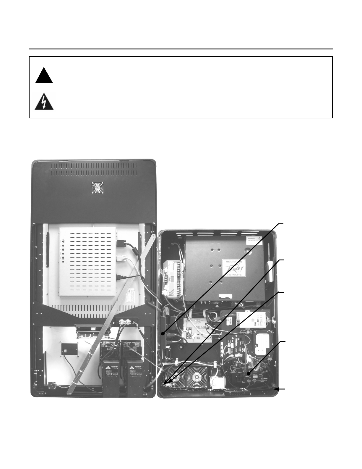
Figure 2-B – Detail View of Power Supply
PRE-AMP
ROUTER
BILL
ACCEPTOR
POWER IN
FROM TRANSFER BOX
LOCATED IN BOTTOM
CENTER OF CABINET
AMPLIFIER
MONITOR
MAIN POWER
ON/OFF
SWITCH
CIRCUIT BREAKER
ATX POWER
SUPPLY

Page 7
Floor
43” to 44”
Wall Mounting Instructions
Choosing the Location
It is recommended that the jukebox be mounted to a
wall with the bottom approximately 35” to 36” up from
the floor. The wall must be strong and flat. The
jukebox should be visible and convenient to use. Do
NOT install directly above a radiator or other source
of heat. Be sure the speaker wires can be easily run
to the unit.
WARNING
The mounting of the jukebox on the wall
should be done by a qualified installer
familiar with wall construction and loading.
The wall and installation hardware MUST be
capable of supporting a 170 lb. load.
Failure to follow these instructions could
result in serious injury.
For easier installation, the Rock-Star Lx is shipped
with the front door detached from the cabinet. After
mounting the cabinet, the front door is easily attached
to the cabinet.
Tools and hardware required for normal installation
into wood wall studs:
•Socket wrench with 7/16” and 3/4” sockets.
•Level
•Pencil
•Punch or Awl (to start the lag screws)
•(4) 1/4” x 1-1/2” Lag screws provided
•Masking Tape
1. Remove the mounting bracket locking bolt from
inside the jukebox (Figure 3-B) to release the
mounting bracket from the back of the jukebox.
Figure 3-B – Inside View of the Top of Cabinet
2. Mount the bracket to the wall with the lower
edge 43” to 44” up from the floor using 1/4” x
1-1/2” lag screws that attach to wooden wall
studs as shown in Figure 4-B. Be sure the
bracket is level.
Figure 4-B – Mounting Bracket on Wall
NOTE: If the wall is concrete, cinder block, brick, or
uses metal wall studs, then the appropriate fasteners
must be used. At least 4” heavy duty fasteners (one
in each corner) must be employed. The fasteners
must be able to support a 170 lb. object. Do NOT
use “press-in” anchors or any other “light” or
“medium” duty fasteners. Consult a contractor
experienced in the type of construction used if there
is any doubt about the strength of the mounting
devices.
3. Prepare the wiring. The power cord should be
attached to the back of the jukebox near the
bottom before mounting. The speaker and other
wiring enter the back of the jukebox near the top
of the hinge side (see Figure 3-B).
4. Place masking tape on the wall where the sides
of the jukebox will be when the unit is hung from
the bracket. The outside of the jukebox is 3-
1/16” from the edges of the wall bracket. (See
Figure 5-B).
Figure 5-B – Mounting Bracket
Wire Access Holes
Bracket Locking Bolt
3-1/16”

Page 8
5. Lift the cabinet onto the wall bracket. It will have
to be lifted about 2” higher than its intended
height. Keep it centered within the tape lines and
keep the back flat against the wall, while slowly
lowering it onto the bracket. When it has dropped
into the slots, replace the bracket locking bolt
(see Figure 3-B). This prevents the unit from
being lifted back off of the wall bracket.
6. Remove the masking tape from the wall.
7. The front door is secured using slide hinges,
which require no tools to attach. To attach the
front door, carefully lift the door and line up the
hinge pins on the cabinet with the mating hinge
barrels on the front door (see Figure 6-B). Then
carefully lower the front door.
Figure 6-B – Detail View of Top Cabinet Hinge with Front Door Opened
WARNING
The next step requires two people who can safely lift 170 lbs.
HINGE BARREL
ON FRONT DOOR
HINGE PIN
ON CABINET

Page 9
8. Using Figure 7-B, locate the free ends of the 3
LCD cables, 2 LED cables and bill acceptor cable
inside the cabinet. Connect these cables from the
cabinet to the front door as shown in Figure 7-B.
9. Using Figure 7-B, locate the free ends of the credit
card reader and ground wire cables on the door.
Connect these cables from the front door to the
cabinet as shown in Figure 7-B.
10. Make sure all cables are dressed properly. Use
the cable clamps in the jukebox to keep cables in
place. Make sure nothing interferes with opening
and closing the door.
Figure 7-B – Inside View of Jukebox with Front Door Opened
CREDIT CARD
READER CABLE
ROUTED HERE
LED & BILL
ACCEPTOR
CABLES ROUTED
IN FRONT OF FANS
VGA CABLE
(FROM VGA
CONNECTOR ON
COMPUTER CORE)
TOUCHSCREEN
CONTROLLER CABLE
(FROM USB PORT ON
COMPUTER CORE)
LCD POWER
CABLE
(FROM POWER SUPPLY)
DUAL BILL
ACCEPTOR CABLE
(FROM P7 ON POWER
SUPPLY AND P19 ON
ROWELINK
CONTROLLER)
SINGLE BILL
ACCEPTOR CABLE
(FROM P7 ON POWER
SUPPLY AND P19 ON
ROWELINK
CONTROLLER)
LED CABLE
(FROM PERIPHERAL
INTERFACE)
LED CABLE
(FROM LED
CONTROLLER
ASSEMBLY)
CREDIT CARD
READER CABLE
(FROM CC READER
TO USB PORT ON
COMPUTER CORE)
GROUND WIRE
ROUTED HERE
GROUND WIRE
(FROM GROUND
SCREW ON DOOR
[ABOUT 3" BELOW
TOP HINGE]
TO GROUND LUG)
LCD CABLES
ROUTED HERE

Page 10
IR Remote Installation Instructions
The Rock-Star Lx comes with an IR remote (located
in the Handy Pack). To install, plug the provided
cable into the provided IR remote receiver (see
Figure 8-B) and route the other end of the cable
through one of the wire access holes in the upper left
corner of the cabinet. Connect the end of the cable
into the port labeled “P11 IR Detector” on the
Rowelink Controller. Install the IR remote receiver
above the jukebox, with a clear line of sight between
the receiver and the handheld transmitter. Plug in
and turn on the jukebox and test the remote (after
installing the hard drive).
Figure 8-B – IR Remote Receiver
Button Functionality on the IR Remote
Transmitter
To enable or disable options on the IR remote, see
“IR Remote Setup” in the Network Setup, Jukebox
Operation, Operator Setup Screens Manual.
The REJECT button is used to cancel (or “Reject”)
the selection currently playing and cancels all
(Rejects all) selections in the queue if held down for 4
seconds. This functionality can be enabled/disabled
through the software.
The POWER button turns the lights, the LCD display,
the bill acceptor(s), and the credit card reader
ON/OFF. To turn them back on and resume normal
operation, press the “POWER” button again.
VOLUME
The CH1+ and CH2+ buttons raise the volume.
The CH1– and CH2– buttons lower the volume.
The PLAY button puts the jukebox in play mode.
The PAUSE button puts the jukebox in pause mode
for a programmed amount of minutes or until the
PLAY button is pushed.
The AP OFF and AP ON buttons turn any
programmed Autoplay mode on/off.
The FUTURE button is used to give a remote credit.
The VID SEL button is reserved for future use.
RECEIVER SHOULD
BE INSTALLED WITH
SENSORS FACING FRONT
CABLE CONNECTED TO
TOP OF RECEIVER

Page 11
Hard Drive Installation Instructions
CAUTION
Hard drives are extremely sensitive to
physical mishandling. Always keep the
hard drives protected from accidental
falls, banging, dust, or liquids.
WARNING
Never install or remove a hard drive when
the unit is powered on. As an extra
precaution, always unplug the power cord at
the power supply before removing or
installing the hard drive.
1. Unlock and open the front door.
2. Make sure the jukebox is turned off and
unplugged.
3. Partially install the 2 provided thumbscrews
in the mounting holes on each side of the
hard drive (see Figure 9-B), leaving about
1/16 of an inch between the hard drive and
the thumbscrew.
4. Install the hard drive into the bracket in the
lower right-side of the jukebox (as shown in
Figure 9-B) and tighten the thumbscrews on
the left side of the hard drive, leaving the
thumbscrews on the right side of the drive
loose.
5. Locate the free ends of the 4-pin hard drive
power cable and the 2 x 20-pin IDE cable.
These cables will be routed out of the bottom
of the computer core near the hard drive.
Connect these cables to the hard drive as
shown in Figure 9-B.
6. Plug in the power cord and turn on the
jukebox by flipping the toggle switch on the
power supply (see Figures 1-B and 2-B) to
the ON position.
Connection Rules
The first time you boot up the jukebox with your hard
drive, a 30-day grace period will begin. If at the end
of these 30 days your jukebox has not connected to
the AMI Entertainment® Network to validate its
licenses, the jukebox will cease to play selections.
In order to properly connect to the network, a valid
trigger code must be entered in the software. To
enter your trigger code, press the SERVICE button
on the Rowelink Controller (see Figure 9-B). On the
touchscreen, touch System Setup and then touch
Enable/Extend Features. Enter the trigger code
provided to you with your hard drive and then press
the Send Code button. The jukebox will display
“Valid trigger code entered” if it accepted your entry.
After the jukebox has made its initial connection to
the AMI Entertainment Network, it must continue to
connect at least once every 7 days to validate its
licenses or the jukebox will cease to play selections.
Figure 9-B – Inside View of Lower-Right Side of Cabinet
THUMBSCREWS
SECURING HARD DRIVE
(
BOTH SIDES
)
4-PIN POWER CABLE
ATTACHED TO HARD DRIVE
2 x 20-PIN IDE CABLE
ATTACHED TO HARD DRIVE
“SERVICE”, “CALIBRATE”,
AND “POWER” BUTTONS ON
ROWELINK CONTROLLER

Page 12
Testing the Unit
Testing the Network
When all of the network connections have been
made, boot up the jukebox. Enter the service mode
by pressing and releasing the “SERVICE” button on
the Rowelink Controller Assembly. To test the
network:
1. Touch the System Setup button and then touch
Advanced Administration.
2. On the Advanced Administration Screen, touch
Configure Server. Then touch the Test
Connection button. This test confirms the
jukebox can connect to AMI’s server (“Server
Found”), and authenticate a connection with
AMI’s server (“Connected”).
3. If the connection is successful, you will see “Yes”
next to “Server Found” and “Connected”. If the
connection fails, you will see “No”. If the
connection fails, check the settings on the
Network Information screen (Diagnostics –>
Network Information). This screen will allow
you to check the IP Configuration and run LAN
and WAN tests.
4. Touch OK and continue with “Testing the
Touchscreen…”.
Testing the Touchscreen, Bill Acceptor(s),
and Credit Card Reader
Touchscreen – Every time a new hard drive is
installed, the touchscreen should be calibrated.
Follow these steps to calibrate.
1. Press the “CALIBRATE” button on the Rowelink
Controller (see Figure 1-B) to launch the
calibration program. This will override the
application while the program runs.
2. Close the jukebox door and make sure it is
locked.
3. Follow the directions on the screen, touching the
center of the targets, and then touching “YES”.
Follow the directions to touch different areas on the
screen to make sure the cursor follows your
movement.
Bill Acceptor(s) and Credit Card Reader –
(NOTE: Credit Card functionality requires a
broadband Internet connection).
1. Press the “SERVICE” button on the Rowelink
Controller to enter service mode.
2. Touch the Diagnostics button.
3. Touch Credit Device Tests.
4. Touch the box next to “Bill Acceptor” and “Credit
Card” (if applicable) to put a check in the box and
enable the test.
5. To test the bill acceptor(s), insert a $1, $5, $10,
and $20 bill (into each bill acceptor, if the jukebox
has two) and check the screen to make sure
proper credit is awarded.
6. To test the credit card reader, swipe a valid credit
card and check that the screen displays the last 5
digits of the card.
7. When finished, touch the Back button to return to
the Main Menu.
Testing the Audio
NOTE: For operators pre-testing the jukebox in their
own facility, any features in the application
associated with the network will not work unless the
jukebox is connected to the Internet.
1. If the jukebox is not in service mode, press the
“SERVICE” button on the Rowelink Controller to
enter service mode.
2. To add one (or more) credit(s) in order to play a
song and test the audio, touch Cash
Management and then touch Credit
Management.
3. Touch the box under “Credits” and a pop-up box
will display.
4. Touch Clear to remove the 0 from the box.
5. Touch 1(or more) and then touch Update.
6. Touch Save on the Credit Management Screen.
7. Touch Exit Service Mode.
8. After connecting speakers to the jukebox (see
section C), play a local music selection to test the
audio.

Page 13
LED Lighting Controller
The LED Control Assembly (see Figure 10-B) controls
all of the decorative lighting for the jukebox. It controls
56 separate ultra-bright RGB LEDs.
The LED Control Assembly provides adjustments for the
following features:
1. Choice of 10 different color and pattern settings.
2. Music Beat Sensitivity (audio cable needed for
operation)
3. Flashing Rate (Speed)
4. Brightness
Speed (Flash Rate)
The Speed (flash rate) can be adjusted from very
rapid to approximately once every 2 seconds.
This Speed control affects the Rainbow Effect, Color
Cycle, and Beat to the Music Modes, but none of the
Single Color Modes.
To adjust the flash rate, turn the Speed dial
counterclockwise to make the flash rate slower, and
clockwise to make it faster.
Brightness
Turn the Brightness control counterclockwise to make
the LEDs dimmer, and clockwise to make them
brighter.
Music Beat Sensitivity for LEDs
(an audio cable is needed for this operation)
The MUSIC control sets the Music Beat Sensitivity.
The Speed control also has an effect on this
adjustment; generally the faster the Speed control is
set, the less influence the music will have on the
LEDs. It is recommended to have a relatively slow
speed setting so the music will have a greater
influence on the LEDs.
To adjust the Music Beat Sensitivity, make a
selection. When it starts playing and you hear the
music, rotate the SPEED control completely
counterclockwise and the MUSIC control completely
clockwise. Slowly turn the MUSIC control
counterclockwise to adjust the Music Beat Pattern.
Then adjust the SPEED control clockwise until you
achieve the desired effect.
If you do not want the LEDs to flash to the music,
rotate the MUSIC control fully counterclockwise.
Figure 10-B – LED Control Assembly
Color and Light Pattern Settings
When the jukebox is in standby, the perimeter lighting
can operate in one of 10 different patterns as outlined
on the following page.
Four DIP Switches are used to set the various
lighting patterns. This will set the pattern that is seen
when the jukebox is muted (in standby) or if music is
playing but the MUSIC control is set to its fully
counterclockwise position. See the chart on the next
page for DIP switch settings.
Note: When changing from one pattern to another,
the new pattern will be start only after the old pattern
has finished its complete cycle and is about to restart
at the beginning.
SPEED
BRIGHTNESS
DIP SWITCHES
MUSIC

Page 14
DIP Switches on LED Lighting Controller for Color and Light Pattern Settings
SW1 SW2 SW3 SW4 Pattern
Off Off Off Off Rainbow Effect (fades from one color to the next)
Off Off Off On
Color Cycle (Aqua, Purple, Blue, Yellow, Green, Red)
This pattern is used when ‘Beat to the Music’ is active and a song is playing.
Off Off On Off Single Color Blue/Green (Aqua)
Off Off On On Single Color Red/Blue (Purple)
Off On Off Off Single Color Blue
Off On Off On Single Color Red/Green (Yellow)
Off On On Off Single Color Green
Off On On On Single Color Red
On Off Off Off Dimmed White
On Off Off On Flashing White

Page 15
Section C -
Audio Description & Operation
•Audio System Description
•Audio System Features and Settings
•Sound & Speaker Set Up
•Connecting to Additional Power Amplifiers
•Connecting a Paging Microphone
•Connecting Speakers to an Audio Transformer
•Setting Volume Zones
•Indicator LEDs
•Signal Inputs & Outputs

Page 16
Audio System Description
Figure 1-C – Rock-Ola
®
/ Peavey
®
Sound System for Rock-Star Lx
The audio system in the Rock-Star Lx jukebox is a
result of collaboration with one of the best commercial
and musical instrument amplifier manufacturers in the
world—Peavey Electronics®.
The Peavey IPR 1600 Power Amplifier is rated at
1600 watts into a 2 ohm load, however, AMI
recommends a load no less than 4 ohms. At 4 ohms,
the Peavey IPR 1600 delivers 530 watts* per channel.
* Watts RMS, 1000 Hz, FTC method
The system consists of a dual stereo (4-channel) pre-
amplifier, combined with a two channel power
amplifier. One pre-amplifier output is designated as
“Internal Output”, the other is designated “External
Output”.
The system may be operated as a single zone or a
dual zone system with separate volume controls for
each zone. Optionally, the system may be configured
to operate up to 4 mono zones. From the factory, the
internal output is sent to the Peavey power amplifier.
Extension speakers are connected directly through an
audio distribution transformer.
Please Note: This section mentions Internal and
External Pre-Amplifier Outputs. With factory default
pre-amplifier and volume control settings, “Internal”
refers to the two channels controlled by the “INT”
volume buttons and normally regulate the extension
speakers’ volume. “External” refers to the 2 channels
controlled by the “EXT” volume buttons. This audio
signal may be used to feed an auxiliary power
amplifier. The standard IR remote control may be
configured to operate the internal and external
channels separately. If an optional Multi-Zone Volume
Control is used, or if you wish to assign your own
zones, the outputs are designated:
Internal Left = Channel 1
Internal Right = Channel 2
External Left = Channel 3
External Right = Channel 4
Specifications and Operating Features
•Separate volume levels for Paid Play and
AutoPlay/Background Play
•Switchable Stereo/Mono Modes
•Separate 5-band equalizers for each channel
•Multiple volume control configurations
•Built-in Paging System input
•Switch setting for microphone gain. Dial control for
maximum microphone volume
•Music Level While Paging settings. Settings are
split to provide separate channel control
•“Always On” amplifier for special event audio and
background music functions. Only if jukebox is
turned off with IR, RF, or optional Multi-Zone
Remote Volume Control.
•Always On Automatic Volume Control (AVC)

Page 17
Audio System Features and Settings
The SyberSonic audio system is preset at the factory
for optimum operation; however, some adjustment
may be required to achieve the best sound or
operating features for your particular environment.
Some audio system settings are in the software and
are easily set using the jukebox touchscreen. Others
are set on the hardware.
The audio system features and adjustments are
described below. Hardware setting instructions are
included here. Instructions for Setting the Pre-
Amplifier Software are in the Network Setup, Jukebox
Operation, Operator Setup Screen Manual.
Volume Control/Zone Settings and Linking –
These are software settings that control the behavior
of the various remote volume controls.
The software is capable of addressing four volume
controls. Rock-Ola’s optional 4-channel volume
control has a fixed address of VCU4 that cannot be
changed. Rock-Ola’s optional 2-channel volume
control is factory set to VCU1, but it may be changed
with DIP switches on the Peripheral Interface. Rowe’s
Volume Control Units may be connected as long as
their address is configured to either VCU2 or VCU3.
(Refer to Rowe’s documentation for setting specifics.)
The default address designations are as follows:
VCU1 = Rock-Ola 2-zone volume control*
VCU2 = Open
VCU3 = Open
VCU4 = Rock-Ola 4-channel volume control
* Both the Rock-Ola 6-Button and Rock-Ola RF Volume Controls
may be connected simultaneously; however, the button functions
cannot be set differently for each.
Stereo/Mono Switch – Sets the audio system to
operate in Stereo or Mono modes. This switch is
preset at the factory to Mono. We recommend
leaving it set this way, as it is necessary for multi-
zone operation.
Equalizer –This is a software setting that changes
speaker tone by increasing or decreasing the
response (gain) of a particular frequency range. Each
of the 4 possible zones/channels has separate
settings.
Balance – Set the channel balance by increasing or
decreasing the power amplifier’s gain controls.
Audio Volume During Paging - Mic Routing –
These software settings establish a fixed volume
level for any music playing during a page. Each of the
4 channels has separate settings. Mic Routing allows
you to set which channel(s) will have the paging
signal allowed/disallowed. This may be used to
create a zoned paging system.
Paging Microphone Volume – Establishes the
maximum paging volume. Set the maximum
microphone volume using the Level knob on the Pre-
Amplifier. A gain switch is also provided to match the
input impedance of the microphone. Instructions to
connect a paging mic can be found on page 19.
Volume Limit –Maximum volume for each channel
may be limited by decreasing the power amplifier’s
gain controls.
Default Volume Level – A preset volume level set in
the software that the jukebox will use upon power up.
This feature can be turned Off or On.
Audio Modes – These are software settings that
control how the jukebox handles normal play,
autoplay, background play, and auxiliary audio. See
the Network Setup, Jukebox Operation, Operator
Setup Screen Manual for details.

Page 18
Sound & Speaker Set Up
The Rock-Star Lx incorporates a 1600 Wrms Power
Amplifier for the speakers. In its default configuration,
the Power Amplifier is connected to the Pre-Amplifier
INT outputs, and volume is adjusted by using the IR
Transmitter. The output of the Power Amplifier is
connected to the 70251-A Audio Transformer unit
which matches power output from the amplifier to
speaker loads. In addition, outputs for 70-volt CV
systems are provided. Note: The 70-volt CV Taps are
rated 150W max per channel.
If more power is required for an installation, the 1600
Wrms amplifier may be replaced with a 2,600 Wrms
Power Amplifier. This optional amplifier may NOT be
used with the 70251-A Audio Distribution
Transformer.
The figure below is a representation of the Audio
Transformer Assembly. Its purpose is to match the
external speaker load to the Peavey Power Amplifier
output so that the optimum amount of power is
delivered to the extension speakers.
For best performance, speakers should be connected
to the highest tap that will not result in an overload.
An overload is defined as any connection scheme
that will cause higher power consumption than the
amplifier is capable of delivering.
The rest of this section assumes that standard equipment – the PV-1600 Power Amplifier and Audio
Transformer Assembly – is used. It is also assumed that you are familiar with the Amplifier Description and
Operation section.
Figure 2-C – Audio Transformer Assembly 70251-A
WARNING: Do NOT
use the 70251-A
Audio Transformer
Assembly with a
PV-2600 Power
Amplifier.
Table of contents