Amico Hummingbird User manual

User Manual
Hummingbird
Mobile Computer Workstations

Important, Please Read Carefully
Thank you for your purchase with Amico.
This unit is designed for long lasting performance, providing the end user complies with assembly and maintenance
procedures. This Instruction Manual is your guide to ensure that you get the best performance out of the equipment.
Amico Accessories Inc. is not responsible for any damage as a result of (but not limited to) abuse and other problems
that may be a direct or indirect result of failure to comply with the instructions provided in this manual.
Please note these key words and symbols:
WARNING Steps where extra care should be taken to prevent injuries and damage.
NOTE Steps that point out helpful information.
Medical Facility Responsibilities
Preventive maintenance checks must be performed regularly to maintain the quality and performance of this product.
Any parts that may be broken, missing, worn, distorted, or contaminated in any way should not be used and all
affected parts should be replaced immediately. Should the necessity of any repair be suspected; please contact your
local distributor or call 877-264-2697.
Preface

Table of Contents
Section 1: Product Specifications 1 - 7
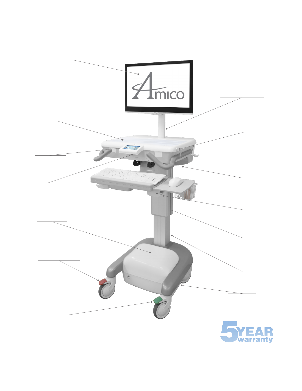
Features 2 - 3
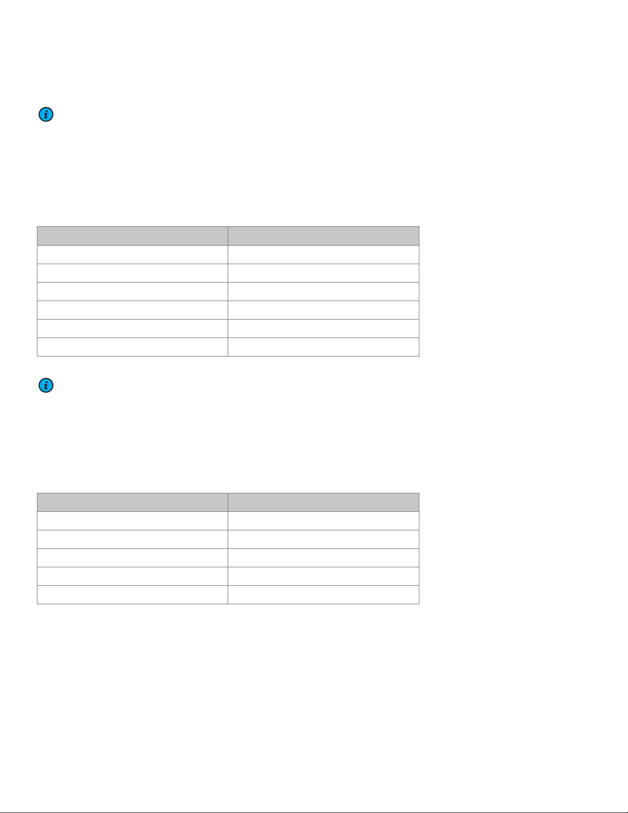
Options Matrix 4 - 7
Powered for LCD 4
Powered for Laptop 5
Non-Powered for LCD 6
Non-Powered for Laptop 7
Section 2: Installation Preparation 8
Installation Tools 8
Pre-Installation Information 8
Section 3: Software Initialization 9 - 12
Section 4: Mounting Platform 13
Section 5: Device Installation 14 - 17
Mounting a Monitor: VESA 75/100 (LCD Carts Only) 14
Mounting a Keyboard and Mouse 15
Mounting a Computer (LCD Carts Only) 16
Mounting a Laptop (Laptop Carts Only) 17
Section 6: Adjustments 18 - 34
Light Interface (Non-Powered Carts Only) 18
Standard Interface (Powered Manual Carts Only) 19
Advanced Interface / Advanced Interface with Automatic Height Control 20 - 21
Manual Height Adjustment 22
Automatic Height Adjustment Standard Interface 23
Automatic Height Adjustment Advanced Interface 24 - 25
Monitor Adjustments (LCD Carts Only) 25
Work Surface 26
Ergonomic Keyboard Tray 27
Standard Keyboard Tray 27
Lockable Casters and Transport Position 28
Spring Adjustment (LCD Carts Only) 29
Resetting the Cart (Reset Button) 30
Resetting the Cart (No Reset Button) 31
Opening the Battery Compartment 32
Charging and Discharge the Battery 33-34
Section 7: Cable Management 35
FIT Cable Management (LCD Cart Only) 35
Section 8: Troubleshooting, Preventative Maintenance, Storage, & Cleaning 36 - 39
Troubleshooting 36 - 37
Preventative Maintenance 38
Product Storage Guidelines 39
Cleaning 39
Amico Warranty Policy 40

1 Amico Accessories Inc.
Display Swivel
and Height Adjustment
Mouse and Barcode
Scanner Holders
Accessory
Mounting Rails
Manual or Electric Lift
LED Base Light
Lockable
PC Compartment
Auxiliary USB Ports
Directional Lock Caster (Green)
Total Lock Caster (Red)
Work Surface with Spill Guard
Control Interface
LED Keyboard Light
LCD, All-in One, Tablet, or Laptop
Optional Battery
Section 1: Product Specifications

www.amico.com 2
Features
Cart Type
Powered
for LCD
Powered
for Laptop
Non-powered
for LCD
Non-powered
for Laptop
Features • Input: 100-240V,
50/60Hz, 6.5A
• 115 VAC, 1.8A
• Output: 19.5 VDC,
10.0A
• 12.0 VDC, 16.5A
• 200W max load
combined
• Input: 100-240V,
50/60Hz, 6.5A
• 115 VAC, 1.8A
• Output: 19.5 VDC,
10.0A
• 12.0 VDC, 16.5A
• 200W max load
combined
Height
Adjustability
Manual/Automatic Manual/Automatic Manual Manual
Note: For weight ranges, please see Table 1 on the next page
Enclosure Ultra-Slim PCs up to
8" x 9" x 2.5"
(203.2 x 228.6 x 63.5 mm)
Laptop enclosure with
screen opening for
laptops up to 17"
(431.8 mm) wide
NOTE: LAPTOP BODY
MUST NOT PROTRUDE
BEHIND THE HINGE OF
THE LAPTOP SCREEN
Ultra-Slim PCs up to
8" x 9" x 2.5"
(203.2 x 228.6 x 63.5 mm)
Laptop enclosure with
screen opening for
laptops up to 17"
(431.8 mm) wide
NOTE: LAPTOP BODY
MUST NOT PROTRUDE
BEHIND THE HINGE OF
THE LAPTOP SCREEN
LCD Mounting
with Interchangeable
Springs for Varying
Monitor Weights
(Table 2 on next page)
Yes – with 180° swivel,
6.5" independent
height adjustment &
landscape to portrait
orientation
No Yes – with 180° swivel,
6.5" independent
height adjustment &
landscape to portrait
orientation
No
Note: For weight ranges, please see Table 2 on the next page
User Interface Standard/Advanced Standard/Advanced Light Light
Casters • 1 x Total Locking
• 1 x Directional
Locking
• 2 x Swivel
• 1 x Total Locking
• 1 x Directional
Locking
• 2 x Swivel
• 1 x Total Locking
• 1 x Directional
Locking
• 2 x Swivel
• 1 x Total Locking
• 1 x Directional
Locking
• 2 x Swivel
Standard Battery
Types
• No Battery
• 1 x LiFePO4
• 2 x LiFePO4
• 3 x LiFePO4
• No Battery
• 1 x LiFePO4
• 2 x LiFePO4
• 3 x LiFePO4
No Battery No Battery
Keyboard Tray
(5 lbs max)
Slide-out, or Ergonomic
with tilt, pivot, slide,
and height adjustment
Slide-out, or Ergonomic
with tilt, pivot, slide,
and height adjustment
Slide-out, or Ergonomic
with tilt, pivot, slide,
and height adjustment
Slide-out, or Ergonomic
with tilt, pivot, slide,
and height adjustment
Lighting Work Surface, Keyboard
Tray and Base
Keyboard Tray and Base Keyboard Tray Keyboard Tray
Section 1: Product Specifications

3 Amico Accessories Inc.
NOTE: ALL CONFIGURATIONS COME WITH AN EASILY DETACHABLE POWER CORD WHICH CAN BE DISCONNECTED
FROM THE CART IF NECESSARY. IF DETACHED, ENSURE CABLE IS FULLY PLUGGED IN BEFORE RESUMING USE.
Various optional storage solutions and additional workstation column mountable accessories are available (Amico
approved accessories and are within footprint of cart only, with some exceptions. Refer to www.amico.com for more
information).
Table 1: Height Adjustability Weight Ranges
Height Adjustability Type Weight Range
Manual 70N Spring 0 - 9.9 lbs (0 - 4.49 kg)
Manual 120N Spring 10 - 19.9 lbs (4.54 - 9.03 kg)
Manual 165N Spring 20 - 29.9 lbs (9.07 - 13.6 kg)
Manual 210N Spring 30 - 39.9 lbs (13.61 - 18.14 kg)
Manual 255N Spring 40 - 49.9 lbs (18.15 - 22.68 kg)
Automatic 50 - 70 lbs (22.68 - 31.75 kg)
NOTE: RATINGS FOR HEIGHT ADJUSTMENT ARE INCLUSIVE OF MAX LOADING ON WORKTOP (E.G., 22 LBS FOR LCD
+ 10 LBS ON WORK SURFACE + 10 LBS IN MAIN BIN + 5 LBS ON KEYBOARD TRAY) AND THE LOAD ON THE
COLUMN.
Table 2: LCD Mounting Weight Ranges
LCD Spring Weight Range
25N 5.5 - 8 lbs (2.5 - 3.6 kg)
35N 7.5 - 10 lbs (3.4 - 4.5 kg)
50N* 13 - 15.5 lbs (5.8 - 7.0 kg)
60N 15.5 - 18 lbs (7 - 8.1 kg)
75N 18 - 22 lbs (8.1 - 19 kg)
*Use MON-LCD-HANDLE for displays between 10 - 13 lbs
Section 1: Product Specifications

www.amico.com 4
Section 1: Product Specifications
Options Matrix
Powered for LCD
* Customer-provided power outlet requires a type C14 coupler as per IEC 60320
standards to receive power from the Hummingbird.
HMF - P - 70 L 60 - U U 57 - M R B E 0
Lifting
Capacity
70
(Manual lift)
0 - 9.9 lbs
(0 - 4.49 kg)
120
(Manual lift)
10 - 19.9 lbs
(4.54 - 9.03 kg)
165
(Manual lift)
20 - 29.99 lbs
(9.07 - 13.6 kg)
210
(Manual lift)
30 - 39.99 lbs
(13.61 - 18.14 kg)
255
(Manual lift)
40 - 49.99 lbs
(18.15 - 22.68 kg)
ELE
(Electric lift)
50 - 70 lbs
(22.68 - 31.75 kg)
ELL
(Electric lift)
50 - 70 lbs
(22.68 - 31.75 kg)
For 3-row Smart
Drawers with
Ergonomic
Keyboard Tray
Combined
weight of
computer,
accessories,
peripherals,
devices,
supplies,
etc. to be
supported by
the lift.
Spring
Strength
(Y)
25
5.5 - 8 lbs
(2.5 - 3.6 kg)
Monitors &
Peripherals
35
7.5 - 10 lbs
(3.4 - 4.5 kg)
Monitors &
Peripherals
50*
13 - 15.5 lbs
(5.8 - 7.0 kg)
Monitors &
Peripherals
60
15.5 - 18 lbs
(7 - 8.1 kg)
Monitors &
Peripherals
75
18 - 22 lbs
(8.1 - 10 kg)
Monitors &
Peripherals
FH
over 22 lbs
(10 kg)
Monitors &
Peripherals
No Height
Adjustment
XX
Custom
(For Monitors &
Peripherals
> 22 lbs (10 kg) or
Fixed Height)
*Use
MON-LCD-HANDLE
for displays
between
10 - 13 lbs
Please
always add
monitor and
peripherals'
weight that
are mounted
onto the IT
post
Cart Power
Outlet
Plug Style
U
United States
2 Flat & 1 Round
Grounding Pin
W
Universal
Various
X
Custom
(Please complete
verification page)
0*
No Power Outlet
Provided
Power out
always at
120V 60Hz
Pure Sine
Control
Interface
M
Standard
for Manual Lift
ONLY
L
Advanced
for Electric Lift
ONLY
Bucket
0
No Bucket
X
Custom Bucket
Keyboard
Tray
0
No Keyboard Tray
S
Slide Out
Keyboard Tray
E
Ergonomic
Keyboard Tray
X
Custom
Keyboard Tray
LCD
Mount
L
Single LCD Mount
Cart
Power
U
United States
2 Flat & 1 Round
Grounding Pin at
110V 60Hz
K
British
3 Rectangular Pins
at 230V 50Hz
A
Australia
2 Flat Metal Pins
Shaped in “V“
with 3rd Flat Pin
in the Center at
230V 50Hz
S
Schuko
2 Round Pins, Top
Pin Grounding
X
Custom
(Please complete
verification page)
Battery
Type
00
No Battery
19
Powered with One
LiFePO4 Battery
38
Powered with Two
LiFePO4 Batteries
57
Powered with
Three LiFePO4
Batteries
42
Powered with One
SLA Battery
Cold
Boot
R
CPU Reset Button
0
No Reset Button
Handle
B
Low Profile Handle

5 Amico Accessories Inc.
Options Matrix
Powered for Laptop
* Customer-provided power outlet requires a type C14 coupler as per IEC 60320
standards to receive power from the Hummingbird.
Section 1: Product Specifications
HML - P - 70 - U U 57 - M R B E
Lifting
Capacity
70
(Manual lift)
0 - 9.9 lbs
(0 - 4.49 kg)
120
(Manual lift)
10 - 19.9 lbs
(4.54 - 9.03 kg)
165
(Manual lift)
20 - 29.99 lbs
(9.07 - 13.6 kg)
210
(Manual lift)
30 - 39.99 lbs
(13.61 - 18.14 kg)
255
(Manual lift)
40 - 49.99 lbs
(18.15 - 22.68 kg)
ELE
(Electric lift)
50 - 70 lbs
(22.68 - 31.75 kg)
ELL
(Electric lift)
50 - 70 lbs
(22.68 - 31.75 kg)
For 3-row Smart
Drawers with
Ergonomic
Keyboard Tray
Combined
weight of
computer,
accessories,
peripherals,
devices,
supplies,
etc. to be
supported by
the lift.
Cart Power
Outlet
Plug Style
U
United States
2 Flat & 1 Round
Grounding Pin
W
Universal
Various
X
Custom
(Please complete
verification page)
0*
No Power Outlet
Provided
Power out
always at
120V 60Hz
Pure Sine
Control
Interface
M
Standard
for Manual Lift
ONLY
L
Advanced
for Electric Lift
ONLY
Keyboard
Tray
0
No Keyboard Tray
S
Slide Out
Keyboard Tray
E
Ergonomic
Keyboard Tray
X
Custom
Keyboard Tray
Cart
Power
U
United States
2 Flat & 1 Round
Grounding Pin at
110V 60Hz
K
British
3 Rectangular Pins
at 230V 50Hz
A
Australia
2 Flat Metal Pins
Shaped in "V"
with 3rd Flat Pin
in the Center at
230V 50 Hz
S
Schuko
2 Round Pins, Top
Pin Grounding
X
Custom
(Please complete
verification page)
Battery
Type
00
No Battery
19
Powered with One
LiFePO4 Battery
38
Powered with Two
LiFePO4 Batteries
57
Powered with
Three LiFePO4
Batteries
42
Powered with One
SLA Battery
Cold
Boot
R
CPU Reset Button
0
No Reset Button
Handle
B
Low Profile Handle

www.amico.com 6
Options Matrix
Non-Powered for LCD
* Customer-provided power outlet requires a type C14 coupler as per IEC 60320
standards to receive power from the Hummingbird.
Section 1: Product Specifications
HMF - N - 70 L 60 - U U - B E 0
Lifting
70
0 - 9.9 lbs
(0 - 4.49 kg)
120
10 - 19.9 lbs
(4.54 - 9.03 kg)
165
20 - 29.99 lbs
(9.07 - 13.6 kg)
210
30 - 39.99 lbs
(13.61 - 18.14 kg)
255
40 - 49.99 lbs
(18.15 - 22.68 kg)
Combined
weight of
computer,
accessories,
peripherals,
devices,
supplies,
etc. to be
supported by
the lift.
Spring
Strength
(Y)
25
5.5 - 8 lbs
(2.5 - 3.6 kg)
Monitors &
Peripherals
35
7.5 - 10 lbs
(3.4 - 4.5 kg)
Monitors &
Peripherals
50*
13 - 15.5 lbs
(5.8 - 7.0 kg)
Monitors &
Peripherals
60
15.5 - 18 lbs
(7 - 8.1 kg)
Monitors &
Peripherals
75
18 - 22 lbs
(8.1 - 10 kg)
Monitors &
Peripherals
FH
over 22 lbs
(10 kg)
Monitors &
Peripherals
No Height
Adjustment
XX
Custom
For Monitors &
Peripherals
> 22 lbs (10 kg) or
Fixed Height
*Use
MON-LCD-HANDLE
for displays
between
10 - 13 lbs
Please
always add
monitor and
peripherals
weight that
are mounted
onto the IT
post
Cart Power
Outlet
Plug Style
U
United States
2 Flat & 1 Round
Grounding Pin
W
Universal
Various
X
Custom
(Please complete
verification page)
0*
No Power Outlet
Provided
Power out
always at
120V 60Hz
Pure Sine
Bucket
0
No Bucket
X
Custom Bucket
Keyboard
Tray
0
No Keyboard Tray
S
Slide Out
Keyboard Tray
E
Ergonomic
Keyboard Tray
X
Custom
Keyboard Tray
LCD
Mount
L
Single LCD Mount
Cart
Power
U
United States
2 Flat & 1 Round
Grounding Pin at
110V 60Hz
K
British
3 Rectangular Pins
at 230V 50Hz
A
Australia
2 Flat Metal Pins
Shaped in “V“
with 3rd Flat Pin
in the Center at
230V 50 Hz
S
Schuko
2 Round Pins, Top
Pin Grounding
X
Custom
(Please complete
verification page)
0
No Power Inlet
Handle
B
Low Profile Handle

7 Amico Accessories Inc.
Options Matrix
Non-Powered for Laptop
* Customer-provided power outlet requires a type C14 coupler as per IEC 60320
standards to receive power from the Hummingbird.
Section 1: Product Specifications
HML - N - 70 - U U - B E
Cart Power
Outlet
Plug Style
U
United States
2 Flat & 1 Round
Grounding Pin
W
Universal
Various
X
Custom
(Please complete
verification page)
0*
No Power Outlet
Provided
Power out
always at
120V 60Hz
Pure Sine
Cart
Power
U
United States
2 Flat & 1 Round
Grounding Pin at
110V 60Hz
K
British
3 Rectangular Pins
at 230V 50Hz
A
Australia
2 Flat Metal Pins
Shaped in “V“
with 3rd Flat Pin
in the Center at
230V 50 Hz
S
Schuko
2 Round Pins, Top
Pin Grounding
X
Custom
(Please complete
verification page)
0
No Power Inlet
Lifting
70
0 - 9.9 lbs
(0 - 4.49 kg)
120
10 - 19.9 lbs
(4.54 - 9.03 kg)
165
20 - 29.99 lbs
(9.07 - 13.6 kg)
210
30 - 39.99 lbs
(13.61 - 18.14 kg)
255
40 - 49.99 lbs
(18.15 - 22.68 kg)
Combined
weight of
computer,
accessories,
peripherals,
devices,
supplies,
etc. to be
supported by
the lift.
Keyboard
Tray
0
No Keyboard Tray
S
Slide Out
Keyboard Tray
E
Ergonomic
Keyboard Tray
X
Custom
Keyboard Tray
Handle
B
Low Profile Handle

www.amico.com 8
Installation Tools
• #2 Philips head screwdriver (LCD cart only)
• Ratchet
• ½" Socket (same drive as ratchet)
• 5/32" Hex key (ball head)
• ¼" Hex key
NOTE: AMICO DOES NOT PROVIDE TOOLS NECESSARY FOR ASSEMBLY.
Pre-Installation Information (PLEASE READ CAREFULLY BEFORE STARTING)
WARNING: LOADING THE PRODUCT OVER THE RATED RANGE CAN LEAD TO STRUCTURAL FAILURE AND/OR
SERIOUS INJURY. PLEASE REFER TO WEIGHT RATING, LOCATED ON THE FIT ASSEMBLY AND ON PAGES 3, 11, 25 &
37-40 OF THIS MANUAL. WEIGHT RATINGS MAY VARY DEPENDING ON MODEL.
WARNING: THE CART IS NOT DESIGNED TO SUPPORT BODY WEIGHT; DO NOT LEAN OR SIT ON THE CART.
WARNING: THE COLUMN OF THE MANUALLY ADJUSTED HUMMINGBIRD MOBILE WORKSTATION CONTAINS A
STRONG GAS SPRING USED FOR VERTICAL ADJUSTMENT OF THE WORK SURFACE. THE COLUMN SHOULD NEVER
BE DISASSEMBLED BY NON-AMICO PERSONNEL. FAILURE TO FOLLOW THESE GUIDELINES COULD RESULT IN
SERIOUS INJURY.
WARNING: DO NOT LEAVE THE CART UNATTENDED ON INCLINES; TIPPING MAY OCCUR RESULTING IN INJURY.
WARNING: DO NOT ATTEMPT TO CARRY THE CART UP/DOWN STAIRS OR OVER/AROUND OBSTACLES. FAILURE TO
FOLLOW THESE GUIDELINES COULD RESULT IN SERIOUS INJURY.
WARNING: DO NOT ALLOW BATTERY COMPARTMENT (AMICO POWER SYSTEM) TO COME IN CONTACT WITH
LIQUIDS. DO NOT OPERATE THE POWER SYSTEM IF WET.
WARNING: THE BATTERY COMPARTMENT SHOULD BE ACCESSED BY AMICO APPROVED SERVICE PERSONNEL
ONLY. UNAUTHORIZED ACCESS COULD RESULT IN INJURY OR DAMAGE TO THE POWER SYSTEM.
WARNING: RISK OF EXPLOSION IF THE BATTERY IS REPLACED BY AN INCORRECT TYPE. DISPOSE OF USED
BATTERIES ACCORDING TO LOCAL REGULATIONS.
NOTE: FOR MORE INFORMATION ON THE POWER SYSTEM, PLEASE REFER TO THE POWER SYSTEM OPERATION
MANUAL AVAILABLE ON THE AMICO WEBSITE.
NOTE: UNITS WITH BATTERIES COME PRE-CHARGED, HOWEVER THEY MUST FIRST BE INITIALIZED BY BRIEFLY
PLUGGING INTO A POWER OUTLET.
NOTE: UNITS WITH AUTOMATIC HEIGHT ADJUSTMENT MUST BE SET TO HOME POSITION AT INITIALIZATION. THIS
WILL BE SHOWN BY THE FLASHING HEIGHT ADJUSTMENT ARROWS ON THE STANDARD USER INTERFACE OR BY A
SYMBOL OF A HOUSE WITH A CROSS THROUGH IT (OR EQUIVALENT) ON THE ADVANCED INTERFACE. TO SET
HOME POSITION, HOLD THE DOWN ARROW UNTIL THE CART STOPS LOWERING AND ONLY THE DOWN ARROW IS
FLASHING (FOR STANDARD INTERFACE) OR THE HOUSE SYMBOL IS GONE (ADVANCED INTERFACE).
Section 2: Installation Preparation

9 Amico Accessories Inc.
1. First Time Initializing:
Plug cart into power outlet – Advanced Interface should turn on (may take up to 30 seconds). After initializing the
cart, a “No Home“ symbol ( ) will appear in the top right hand corner of the Advanced Interface. This means the
user must set the cart's "Home" (lowest) position.
2. Setting Home Position:
1. Hold the Down arrow to lower the cart's work surface until the collision symbol ( ) appears.
2. Release the Down arrow and reverse direction to raise work surface to desired position.
3. Setting Time and Date:
1. Tap on “Guest“ in top left corner of interface (Figure 1).
2. Select “Admin“ from drop down list and login using password: AMICO (Figure 2).
3. Tap on “Settings“ icon.
4. Select “Admin Setup“ (Only available in the ADMIN profile).
5. Select “Set Clock“.
6. Using the arrow icons set the time and date in the desired format (note: date and time formats must first be
selected on right of interface). Tap Save to finish.
Figure 1
Settings Notes
4:50 pm07/10/2014
Timer
10h:50m
GUEST
Top Middle Bottom
Figure 2
4:50 pm07/10/2014 10h:50m
Guest
USER NAME
PASSWORD
LOG IN
NEW USER
CANCEL
QW E R T Y U IO P
AS D F G H J KL Enter
ZX C V B N M .abc
Bk
123 123#+= #+=
Section 3: Software Initialization
Installation and Adjustment Instructions
Powered Cart with Advanced Interface (Automatic Height Adjustment)
Quick Setup
Medical Facility Responsibility
WARNING: THIS QUICK-GUIDE IS NOT A REPLACEMENT FOR THE FULL MANUAL. IT IS THE RESPONSIBILITY OF THE
END USER TO ENSURE ALL ASPECTS OF THE INSTALLATION ARE COVERED BY FOLLOWING THE FULL MANUAL.
NOTE: INSPECT CART INTEGRITY PRIOR TO BEGINNING SETUP.

www.amico.com 10
Figure 3
4:50 pm07/10/2014 10h:50m
GUEST
USER NAME
User Name
BACK
NEXT
QW E R T Y U IO P
AS D F G H J KL Enter
ZX C V B N M .abc
Bk
123 123#+= #+=
4. Creating a User Profile:
1. Tap on “Admin“in top left corner of interface and select “Logout”when prompted.
2. Tap “Guest”in top left corner of interface, and select “New User”.
3. Enter desired User Name, select Next.
4. Enter desired Password, select Next (re-enter password and select Next).
5. Enter the user's height. Select Next then OK when prompted.
5. Setting “Sit“ Heights:
Note: User's forearms should be parallel to ground (90-degree bend at elbows) for ergonomic use.
1. To input sit and stand positions, select Settings and then User Setup (Figure 3).
2. Adjust the height using the Up/Down arrows. When height is at desired sit position, select Save next to
respective position icons.
6. Setting “Stand“ Heights:
1. To input sit and stand positions, select Settings and then User Setup (Figure 3).
2. Adjust the height using the Up/Down arrows. When height is at desired stand position, select Save next to
respective position icons.
3. Tap OK twice to return to Main Menu.
Section 3: Software Initialization

11 Amico Accessories Inc.
Figure 1
4:50 pm07/10/2014 10h:50m
Guest
USER NAME
PASSWORD
LOG IN
NEW USER
CANCEL
QW E R T Y U IO P
AS D F G H J KL Enter
ZX C V B N M .abc
Bk
123 123#+= #+=
1. First Time Initializing:
Plug cart into power outlet – Advanced Interface should turn on (may take up to 30 seconds).
2. Setting Time and Date:
1. Tap on “Guest”in top left corner of interface.
2. Select “Admin”from drop down list and login using password: AMICO (Figure 1).
3. Top on “Settings”icon.
4. Select “Admin Setup”(Only available in the ADMIN profile).
5. Select “Set Clock”.
6. Using the arrow icons set the time and date in the desired format (note: date and time formats must first be
selected on right of interface). Tap Save to finish.
Section 3: Software Initialization
Installation and Adjustment Instructions
Powered Cart with Advanced Interface (Manual Height Adjustment)
Quick Setup
Medical Facility Responsibility
WARNING: THIS QUICK-GUIDE IS NOT A REPLACEMENT FOR THE FULL MANUAL. IT IS THE RESPONSIBILITY OF THE
END USER TO ENSURE ALL ASPECTS OF THE INSTALLATION ARE COVERED BY FOLLOWING THE FULL MANUAL.
NOTE: INSPECT CART INTEGRITY PRIOR TO BEGINNING SETUP.

www.amico.com 12
Figure 2
4:50 pm07/10/2014 10h:50m
Peter
USER NAME
User Name
BACK
NEXT
QW E R T Y U IO P
AS D F G H J KL Enter
ZX C V B N M .abc
Bk
123 123#+= #+=
Guest
Figure 3
DESCRIPTION:
PART NO:
SCALE:
DRAWN BY:
CHECKED BY:
SHT.
OF
DRAWING NO:
NTS
DATE:
DATE:
PROJECTION
www.amico.com
3. Creating a User Profile:
1. Tap on “Admin“ in top left corner of interface and select “Logout“ when prompted.
2. Tap “Guest“ in top left corner of interface, and select “New User“.
3. Enter desired User Name, select Next (Figure 2).
4. Enter desired Password, select Next (re-enter password and select Next).
4. Height Adjustment:
1. Pull lever and adjust to desired height (Figure 3).
Section 3: Software Initialization

13 Amico Accessories Inc.
Section 4: Mounting Platform
The Hummingbird Mobile Workstation is intended for use on flat surfaces (carpet, tile, wood, laminate) in an indoor
environment and on inclines of up to 10°.
The Hummingbird Mobile Workstation includes a directional locking caster (green) to aid in movement and
maneuvering corners, and a total locking caster (red) to prevent movement as well as 2 handles for steering.
DESCRIPTION:
PART NO:
SCALE:
DRAWN BY:
CHECKED BY:
SHT.
OF
DRAWING NO:
NTS
DATE:
DATE:
PROJECTION
www.amico.com

www.amico.com 14
Mounting a Monitor: VESA 75/100 (LCD Carts Only)
WARNING: ENSURE THAT THE VESA PLATE IS AT THE TOPMOST POSITION BEFORE MOUNTING OR REMOVING
DEVICES FROM THE FIT POST.
NOTE: 4 x M4 SCREWS ARE PROVIDED FOR MOUNTING THE MONITOR TO THE VESA HEAD. DIFFERENT SCREWS
MAY BE REQUIRED IF THE HOLE DEPTH IN THE MONITOR DOES NOT MATCH THE SCREW SIZE. STANDOFFS MAY BE
NEEDED DEPENDING ON THE MONITOR'S HOLE PATTERN.
NOTE: ALLOW 90°ROTATION IN BOTH DIRECTIONS FOR EXCESS CABLING.
1. Determine the mounting configuration on the monitor – VESA 75 (75 mm x 75 mm M4 thread) or VESA 100 (100
mm x 100 mm M4 thread).
2. VESA 100 Configuration: Partially thread 2 M4 screws into top 2 holes in the back of the monitor. The monitor
can then be hung on the VESA plate through the two slots at the top. Insert 2 more screws through the VESA 100
mounting holes at the bottom and tighten all screws (Figure 1).
3. VESA 75 Configuration: Rotate the VESA Plate so that the 2 slots for the VESA 75 configuration are located at the
top of the plate. Partially thread 2 M4 screws into top 2 holes in the back of the monitor. The monitor can then be
hung on the VESA plate through the two slots at the top. Insert 2 more screws through the VESA 75 mounting holes
at the bottom and tighten all screws.
4. When removing the monitor, ensure that the monitor is at the topmost position (applicable only when FIT Post
contains a gas spring for vertical adjustability). Remove the 2 bottom screws from the VESA plate, and loosen the
top 2 screws. Carefully lift the monitor off the VESA plate.
Figure 1: VESA Plate
M4 mounting holes
for VESA-100
Section 5: Device Installation
M4 mounting holes
for VESA-75

15 Amico Accessories Inc.
Mounting a Keyboard and Mouse
1. Remove the backing on 3 (or half of given) dual locking pads and adhere to bottom of keyboard, spaced evenly
apart (Figure 1).
2. Remove the backing on the remaining dual locking coins and attach them to those on the bottom of the keyboard
(Figure 2).
3. Carefully position the keyboard on the keyboard tray and firmly press down while supporting the keyboard tray
from the bottom (Figure 3).
4. Place the mouse into the mouse holder (Figure 4).
5. Secure the mouse and keyboard cords to the back of the keyboard tray (Figure 5).
6. Route the cords through the bottom of the main bin (Figure 6). Ensure that there is enough slack in the cords for
full adjustability of the keyboard tray into the progessor port (outer most position).
WARNING: DO NOT OVERLOAD OR LEAN ON THE KEYBOARD TRAY (MAX LOAD = 10 LBS).
Section 5: Device Installation
Figure 1 Figure 2 Figure 3
Figure 4 Figure 5 Figure 6
(View underneath bin)
Dual Locking Coins

www.amico.com 16
Mounting a Computer (LCD Carts Only)
1. To open the Work Surface, insert the key (provided by Amico) into the lock on the Work Surface and turn
counterclockwise (CCW) to unlock the Work Surface.
2. Lift the Work Surface upwards (as shown in Figure 1) to access the interior of the main bin.
3. Place the computer (not provided) carefully inside the main bin and plug the power cord into the supplied power
bar. See page 2 for size restrictions.
4. Plug all USB cables into the computer.
NOTE: A USB HUB NOT PROVIDED MAY BE REQUIRED.
5. To close, lower the Work Surface until it is resting on the main bin and turn the key clockwise (CW) to lock.
WARNING: ENSURE THAT THE KEY IS TURNED COUNTERCLOCKWISE BEFORE ATTEMPTING TO CLOSE THE WORK
SURFACE. FAILURE TO DO SO COULD LEAD TO DAMAGE TO THE WORK SURFACE AND/OR THE LOCKING
MECHANISM.
Section 5: Device Installation
Figure 1 Figure 2
Power Bar
Computer
(not provided)
Work Surface
Work Surface Lock
Main Bin
Unlock Lock
Open
Close

17 Amico Accessories Inc.
Mounting a Laptop (Laptop Carts Only)
1. To open the Work Surface, insert the key (provided by Amico) into lock on Work Surface and turn counterclockwise
(CCW) to unlock the Work Surface (Figure 1).
2. Lift the Work Surface upwards to access the interior of the main bin.
3. Place a laptop (not provided) carefully inside the main bin and plug the power cord into the supplied power bar.
Adjust the height and fit with the supplied bumpers as needed (see page 2 for size restrictions).
4. Plug all USB cables into the laptop.
NOTE: A USB HUB NOT PROVIDED MAY BE REQUIRED.
5. To close, lower the Work Surface until it is resting on the main bin and turn the key clockwise (CW) to lock.
NOTE: WITH THE SPRINGLOADED BUMPER ON THE INSIDE OF THE WORK SURFACE, IT MAY BE NECESSARY
TO PRESS DOWN ON THE WORK SURFACE WHILE LOCKING.
WARNING: ENSURE THE KEY IS TURNED COUNTERCLOCKWISE BEFORE ATTEMPTING TO CLOSE THE WORK
SURFACE. FAILURE TO DO SO COULD LEAD TO DAMAGE TO THE WORK SURFACE AND/OR LOCKING MECHANISM.
NOTE: REFER TO THE LAPTOP BUMPER INSTALLATION MANUAL FOR MORE DETAILED INSTRUCTIONS.
Section 5: Device Installation
Figure 2
Figure 3 Figure 4
Figure 1
DESCRIPTION:
PART NO:
SCALE:
DRAWN BY:
CHECKED BY:
SHT.
OF
DRAWING NO:
NTS
DATE:
DATE:
PROJECTION
www.amico.com
Work Surface Lock
Main Bin
Unlock Lock
Open
Close
Other manuals for Hummingbird
1
This manual suits for next models
4
Table of contents
Other Amico Desktop manuals
Popular Desktop manuals by other brands

Compaq
Compaq Presario 7360 Maintenance and service guide

Steiger Dynamics
Steiger Dynamics LEET user manual

HP
HP Compaq Presario quick start guide

Lenovo
Lenovo 57094408 - IdeaCentre H210 5355AFU Desktop Replacement guide

Dell
Dell OptiPlex DCCY Setup and quick reference guide

Zotac
Zotac ZBOX P Series quick start guide