AMIMON CONNEX ProSight Operating instructions

Doc P/N: 9040962 | Rev 06 | Printed 17 August 2017
Installation and Operation Guide
Copyright © 2016-2017 Amimon LTD, All rights reserved. No part of this publication may be reproduced, transmitted,
transcribed, stored in a retrieval system, or translated into any language or computer language, in any form or by any means,
electronic, mechanical or otherwise without prior written permission of Amimon LTD.
CONNEX ProSight
1

Home Page
Safety
Introduction to CONNEX
ProSight
Opening the Package
Installing the Units
Operating the Units
Configuration Using
ProSight Mobile
Application
Specifications
Appendices
2
Home Page|
Doc P/N: 9040962 | Rev 06 | Printed 17 August 2017
Navigation pane Home Page
Home Page
Safety
Safety Instructions
Potential Hazards
Introduction to CONNEX ProSight
Overview
Quick Installation Layout
Opening the Package
HD Receiver Accessories
HD Transmitter Accessories
Installing the Units
Connecting Components to Drone
Preparing the Mounting Plate
Attaching the HD Transmitter
Mounting the Camera
Wiring and Installing the Antenna
Wiring the HD Transmitter
Wiring the Telemetry Cable
Configuring a Flight Controller that Runs
CleanFlight
OSD Information Delivered from the Flight
Controller
Installing the HD Receiver
Wiring the HD Receiver
Operating the Units
Pairing HD Transmitter and Receiver
OSD Control
Prerequisite
Navigating in OSD Menus
Switching between OSD Modes
OSD Menu Interface
Main Menu
Setup Menu
Connecting to Transmitter
Frequency Management
Selecting Frequency Mode via OSD
Auto
Fixed
Setup Menu Options
Viewing Status
Setting Regional RF
Selecting Battery Type
Setting Power Alert Threshold
Setting OSD Overlays
Setting Telemetry Color
Managing Bluetooth Communication
Managing Camera Settings
Setting Video Mode
Color Mode
Saturation Mode
Switching to Indoor Mode
Switching to Night Mode
Flipping the Camera Image
Configuration Using ProSight Desktop
Application
Prerequisite
Installing the Desktop Application
Connecting to the HD Transmitter and Receiver
Upgrading Firmware
Editing Device Name
Restoring Factory Configuration Settings
Configuration Using ProSight Mobile
Application
Initial Setup
Home Screen Overview
Pairing with a Receiver via Bluetooth
Viewing Device Parameters
Main Menu Options
Spectrum Analyzer
Using the OSD Swipe Controller
Frequency Management
Specifications
CONNEX ProSight
HD Transmitter
ProSight HX Camera
ProSight Camera
HD Receiver
Appendices
ProSight Delay-Free HD Camera
Prosight HX Camera
Video Modes
ProSight Camera
Video Modes
Technology and Output
Size Factor Flexibility and Setup
CONNEX ProSight Antenna Guidelines
Full 5GHZ Frequency Band Support
Antenna Configuration
Line of Sight
Platform Considerations
CONNEX ProSight Frequency Management
Frequency Management Tools
Ease of Use
Automatic Frequency Selection
Manual Frequency Selection
Regional Frequency Specifications
Regional Frequency Table
CONNEX ProSight Installation and Operation Guide

Home Page
Safety
Introduction to CONNEX
ProSight
Opening the Package
Installing the Units
Operating the Units
Configuration Using
ProSight Mobile
Application
Specifications
Appendices
3
Safety|Safety Instructions
Doc P/N: 9040962 | Rev 06 | Printed 17 August 2017
Navigation pane Safety
Safety Instructions
• Do not open the HD transmitter or HD receiver enclosures. There are no user-serviceable parts inside. Refer servicing to qualified
service personnel only. The use of controls, adjustments or procedures other than those specified in this user guide may result in
exposure to shock and/or electrical or mechanical hazards.
• Do not immerse the units in water.
• Always disconnect a unit’s power by disconnecting the main plug.
• Clean with a dry cloth only.
• Keep powered on units at least 20 cm away from your body.
• Do not expose the units to moisture or excessive heat. Unit operating temperature is 320F-1130F (00C-400C).
• Unplug the units during lightning storms and long storage periods.
• For CONNEX ProSight receiver only – the provided power supply is for indoor use only.
• Use only the supplied accessories or those recommended on the AMIMON website. Accessories (including cables) must not be replaced,
as this may affect performance or functionality, or damage the unit. We highly recommend that you use the provided AMIMON cables. If
an alternate cable is used, make sure that it is of the highest quality.
• Do not use the product if there is any physical damage to the enclosure.
• For CONNEX ProSight transmitter only – it is normal for the transmitter to become slightly hot during use. However, if the enclosure’s
temperature becomes too hot to touch, turn the transmitter off and contact support.
• Do not let the product come into contact with corrosive materials.
• Do not let the product come into contact with fire.
CONNEX ProSight Installation and Operation Guide

Home Page
Safety
Introduction to CONNEX
ProSight
Opening the Package
Installing the Units
Operating the Units
Configuration Using
ProSight Mobile
Application
Specifications
Appendices
4
Safety|Potential Hazards
Doc P/N: 9040962 | Rev 06 | Printed 17 August 2017
Navigation pane Potential Hazards
The CONNEX ProSight HD transmitter and HD receiver contain HD wireless video module devices that should be operated according to the same
rules and limitations applicable to normal HD wireless video module devices. Do not operate the units in environments that may be susceptible to
radio interference resulting in danger, specifically:
• Areas where prohibited by law – follow any special rules and regulations and obey all signs and notices. Always ensure that the unit is
turned off (the LED is not lit) when instructed to do so or whenever it may cause interference or danger.
• Where an explosive atmosphere may be present – do not operate the CONNEX ProSight unit in any area where a potentially
explosive atmosphere may exist. Sparks in such areas could cause an explosion or fire, resulting in bodily injury or even death. Be aware
and comply with all signs and instructions.
• It is inadvisable to operate the CONNEX ProSight unit while at a refueling point or service station – users are reminded to
observe restrictions on the use of radio equipment in fuel depots (fuel storage and distribution areas), chemical plants or where blasting
operations are in progress.
• Areas with a potentially explosive atmosphere are often, but not always, clearly marked – potential locations can include gas
stations, below deck on boats, chemical transfer or storage facilities, vehicles using liquefied petroleum gas (such as propane or butane),
areas where the air contains chemicals or particles (such as grain, dust or metal powders), and any other area where it would normally
be advisable to turn off a vehicle’s engine.
• Near medical and life support equipment – do not operate the CONNEX ProSight unit in any area where medical equipment
or life support equipment is in use, or near any equipment that may be susceptible to any form of radio interference. As the CONNEX ProSight
unit may transmit signals that could interfere with this equipment, the host communications device must be turned off in such areas.
For more information, visit www.AMIMON.com.
CONNEX ProSight Installation and Operation Guide

Home Page
Safety
Introduction to CONNEX
ProSight
Opening the Package
Installing the Units
Operating the Units
Configuration Using
ProSight Mobile
Application
Specifications
Appendices
5
Introduction to CONNEX ProSight|Overview
Doc P/N: 9040962 | Rev 06 | Printed 17 August 2017
Navigation pane Introduction to CONNEX ProSight
Overview
CONNEX ProSight is the missing link in a new era in FPV racing. CONNEX ProSight transforms FPV drones into a completely new kind of
immersive experience for beginners and experts alike.
CONNEX ProSight delivers unparalleled vision performance with delay-free wireless transmission. Superior image quality combined with ease of
installation, smooth configuration, and improved experience for multi-pilot flying provides unmatched usability.
CONNEX ProSight consists of the following components:
• HD receiver (see HD Receiver Accessories)
• HD transmitter (see HD Transmitter Accessories)
• HD Camera - two types of cameras, ProSight and ProSight HX, are available to connect to the CONNEX ProSight featuring camera
mount and dampers:
»ProSight HX Camera – 720p60 with latency under 1mil/sec, and 25 Mhz Bandwidth.
»ProSight Camera – 720p30, 13 Mhz Bandwidth.
• Cables and antennas, described in the following sections
CONNEX ProSight Installation and Operation Guide

Home Page
Safety
Introduction to CONNEX
ProSight
Opening the Package
Installing the Units
Operating the Units
Configuration Using
ProSight Mobile
Application
Specifications
Appendices
6
Introduction to CONNEX ProSight|Quick Installation Layout
Doc P/N: 9040962 | Rev 06 | Printed 17 August 2017
Navigation pane Quick Installation Layout
Flight controller
Pairing with an additional receiver/transmitter
5. Connect HD receiver
power and video
4.
Connect transmitter power
3.
Connect to flight controller
1.
Connect camera
2. Connect antenna cables
Keep the camera cable
as far as possible from
any high power cables
and ESCs.
The delivered transmitter and receiver are already paired.
Connect the units with a USB cable and USB to USB OTG adapter.
Paring is done automatically. Verify link LED is constantly ON.
6. Verify
communication
For best range and link
robustness, route the cable
away from the antenna body.
2S-4S battery,
7-17V
2S-4S battery,
7-17V
Caution:
The antenna cable minimum
bend radius is 5mm.
The camera cable should be
connected vertically to the connector
to avoid physical damage to the
connector's pins.
CONNEX ProSight Installation and Operation Guide

Home Page
Safety
Introduction to CONNEX
ProSight
Opening the Package
Installing the Units
Operating the Units
Configuration Using
ProSight Mobile
Application
Specifications
Appendices
7
Opening the Package|Quick Installation Layout
Doc P/N: 9040962 | Rev 06 | Printed 17 August 2017
Navigation pane Opening the Package
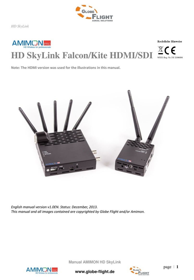
Verify that the ProSight package contains the following items:
• HD receiver
• HD transmitter
• HDR camera, mount and dampers
• Spacers and screws
• Cables and antennas, described in the following sections
Note:
One of the following HDR cameras can be connected to the CONNEX ProSight:
• ProSight HX Camera – 720p60 with latency under 1mil/sec, and 25 MHz bandwidth.
• ProSight Camera – 720p30, 13 MHz bandwidth.
CONNEX ProSight Installation and Operation Guide
Home Page
Safety
Introduction to CONNEX
ProSight
Opening the Package
Installing the Units
Operating the Units
Configuration Using
ProSight Mobile
Application
Specifications
Appendices
8
Opening the Package|HD Receiver Accessories
Doc P/N: 9040962 | Rev 06 | Printed 17 August 2017
Navigation pane HD Receiver Accessories
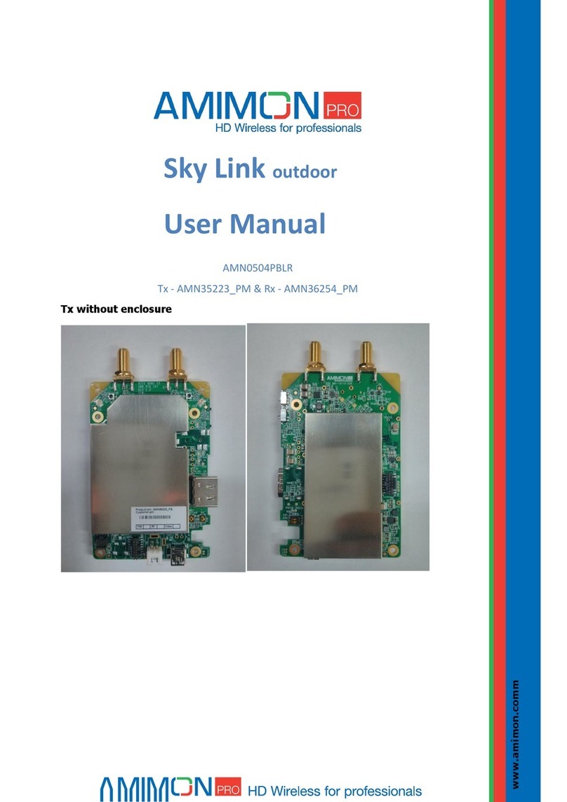
Name Descripon
HDMI Cable
AMN_CBL_036A
HD receiver Standard HDMI Cable (Type A to Type A)
Connects the HD receiver to a video monitor or FPV goggles.
HD Receiver Power
Cable
AMN_CBL_038A
A non-splier cable (DC Jack to XT-60 connector). Connects
between the HD receiver power port and a power source.
HD Receiver Antennas
AMN_ACC_002 5 antennas, connected to the HD receiver.
Micro USB Cable
AMN_CBL_034A
Standard Micro USB cable for soware upgrading. This cable
can be used for the HD receiver and the HD transmier.
OTG Cable
AMN_CBL_060
Connects the HD transmier and the HD receiver for the
pairing process (see Pairing HD Transmitter and Receiver)
CONNEX ProSight Installation and Operation Guide
Home Page
Safety
Introduction to CONNEX
ProSight
Opening the Package
Installing the Units
Operating the Units
Configuration Using
ProSight Mobile
Application
Specifications
Appendices
9
Opening the Package|HD Transmitter Accessories
Doc P/N: 9040962 | Rev 06 | Printed 17 August 2017
Navigation pane HD Transmitter Accessories
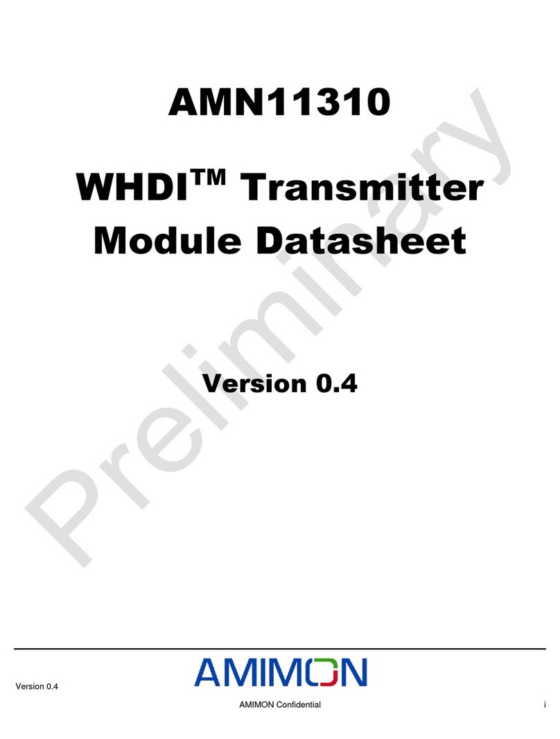
Name Descripon
HD Transmier
Antennas
AMC_ACC_018
2 antennas, pre-assembled in the antenna bracket,
connected to the HD transmier.
CC3D Telemetry Cable
AMN_CBL_66 Connects the ight controller and the HD transmier.
Naze Telemetry Cable
AMN_CBL_71
A split telemetry cable, connects the HD transmier and the
Naze ight controller.
CONNEX ProSight Installation and Operation Guide
Home Page
Safety
Introduction to CONNEX
ProSight
Opening the Package
Installing the Units
Operating the Units
Configuration Using
ProSight Mobile
Application
Specifications
Appendices
10
Opening the Package|HD Transmitter Accessories
Doc P/N: 9040962 | Rev 06 | Printed 17 August 2017
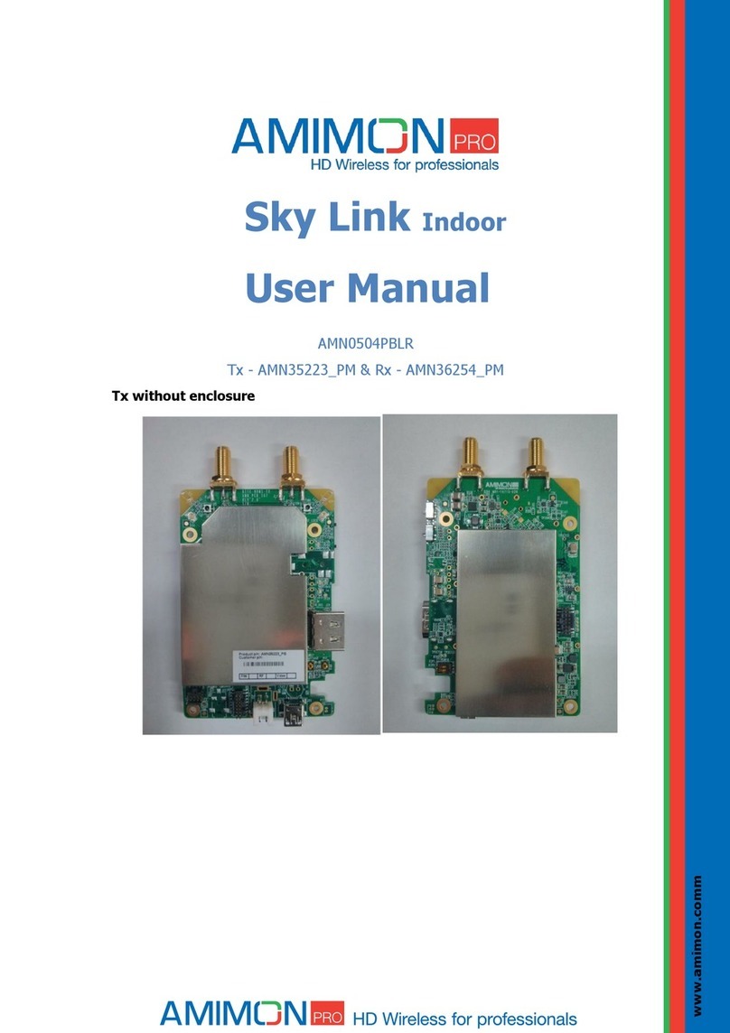
Navigation pane Name Descripon
HD Transmier Power
Cable
AMN_CBL_030A
Connects the HD transmier to an external power source.
Camera Cable
AMN_CBL_65 Connects the camera and the HD transmier.
CONNEX ProSight Installation and Operation Guide
Home Page
Safety
Introduction to CONNEX
ProSight
Opening the Package
Installing the Units
Operating the Units
Configuration Using
ProSight Mobile
Application
Specifications
Appendices
11
Installing the Units|HD Transmitter Accessories
Doc P/N: 9040962 | Rev 06 | Printed 17 August 2017
Navigation pane Installing the Units
The following sections describe the mechanical installation and wiring of ProSight system parts:
• Connecting Components to Drone
• Installing the HD Receiver
• Wiring the HD Receiver
CONNEX ProSight Installation and Operation Guide

Home Page
Safety
Introduction to CONNEX
ProSight
Opening the Package
Installing the Units
Operating the Units
Configuration Using
ProSight Mobile
Application
Specifications
Appendices
12
Installing the Units|Connecting Components to Drone
Doc P/N: 9040962 | Rev 06 | Printed 17 August 2017
Navigation pane Connecting Components to Drone
Preparing the Mounting Plate
Mark mounting holes for the following components:
• Camera (1) – 3 holes
• Transmitter (3) – 4 holes
• Antenna (4) – 4 holes
1
2
3
4
Notes:
• Consider the Camera Cable length (2 3/4inch / 7cm) between the camera and the transmitter (2).
• The HD transmitter heats up quickly. For optimum functionality, install the HD transmitter in a well ventilated location
on the drone.
CONNEX ProSight Installation and Operation Guide

Home Page
Safety
Introduction to CONNEX
ProSight
Opening the Package
Installing the Units
Operating the Units
Configuration Using
ProSight Mobile
Application
Specifications
Appendices
13
Installing the Units|Connecting Components to Drone
Doc P/N: 9040962 | Rev 06 | Printed 17 August 2017
Navigation pane Attaching the HD Transmitter
The following procedure describes HD transmitter installation.
1. Connect the 4 mounting bases (1) to the mounting plate
using 4 screws (2).
2. Place the HD transmitter (4) on the 4 mounting bases (3).
1
2
Flight direction
4
3
CONNEX ProSight Installation and Operation Guide

Home Page
Safety
Introduction to CONNEX
ProSight
Opening the Package
Installing the Units
Operating the Units
Configuration Using
ProSight Mobile
Application
Specifications
Appendices
14
Installing the Units|Connecting Components to Drone
Doc P/N: 9040962 | Rev 06 | Printed 17 August 2017
Navigation pane 3. Connect the HD transmitter to the mounting bases
using 4 screws (1).
1
Flight direction
2
3
Note:
Notice the transmitter orientation. The video connector (2) should
face the camera and the antenna sockets (3) must remain exposed.
CONNEX ProSight Installation and Operation Guide

Home Page
Safety
Introduction to CONNEX
ProSight
Opening the Package
Installing the Units
Operating the Units
Configuration Using
ProSight Mobile
Application
Specifications
Appendices
15
Installing the Units|Connecting Components to Drone
Doc P/N: 9040962 | Rev 06 | Printed 17 August 2017
Navigation pane Mounting the Camera
Mount the camera on the front of the drone mounting plate.
The rubber vibration dampers serve as shock absorbers and help
reduce the “Jello” effect in the incoming video.
1. Insert the rubber dampers (3) through the mounting holes in the
camera base (2) and in the drone mounting plate (1).
2. Secure the damper pins (4) and locking clips (5).
3
2
1
4
5
4
Tip:
The camera can be installed using screws instead of dampers.
CONNEX ProSight Installation and Operation Guide

Home Page
Safety
Introduction to CONNEX
ProSight
Opening the Package
Installing the Units
Operating the Units
Configuration Using
ProSight Mobile
Application
Specifications
Appendices
16
Installing the Units|Connecting Components to Drone
Doc P/N: 9040962 | Rev 06 | Printed 17 August 2017
Navigation pane The camera can be adjusted or flipped:
3. Release the two screws (1).
4. Set the angle of the camera or flip it 1800, and fasten the two
screws (1).
1
1
21
Tip:
The camera image can also be flipped by applying an OSD
command (see Switching to Indoor Mode).
CONNEX ProSight Installation and Operation Guide

Home Page
Safety
Introduction to CONNEX
ProSight
Opening the Package
Installing the Units
Operating the Units
Configuration Using
ProSight Mobile
Application
Specifications
Appendices
17
Installing the Units|Connecting Components to Drone
Doc P/N: 9040962 | Rev 06 | Printed 17 August 2017
Navigation pane Wiring and Installing the Antenna
This section reviews the tasks associated with installing and wiring
the HD Transmitter Antennas.
A- Connecting the Antenna to the Drone
1. Verify the antenna cables (1) are inserted in the base groove (3).
Tip:
If you decide to design your own antenna fixture, we recommend
following the CONNEX ProSight Antenna Guidelines 1.0.
2
3
1
CONNEX ProSight Installation and Operation Guide

Home Page
Safety
Introduction to CONNEX
ProSight
Opening the Package
Installing the Units
Operating the Units
Configuration Using
ProSight Mobile
Application
Specifications
Appendices
18
Installing the Units|Connecting Components to Drone
Doc P/N: 9040962 | Rev 06 | Printed 17 August 2017
Navigation pane 2. Place the antenna on the rear side of the drone mounting plate.
3. Fasten the antenna base to the drone with four screws (1) using
washers (2) and nuts (3).
B- Connecting Antenna to HD Transmitter
1. Route the antenna cables from the base of the antenna holder to
the HD transmitter (3).
2. Connect the two HD Transmitter Antennas (1) to the coax sockets
(2).
3. Secure the antenna cables.
3
1
2
Tip:
The antenna can be connected to the drone using zip ties instead of
screws.
1
23
Note:
Be sure the antenna cable loop is maintained. The cable’s minimum
bend radius is 5mm.
CONNEX ProSight Installation and Operation Guide

Home Page
Safety
Introduction to CONNEX
ProSight
Opening the Package
Installing the Units
Operating the Units
Configuration Using
ProSight Mobile
Application
Specifications
Appendices
19
Installing the Units|Wiring the HD Transmitter
Doc P/N: 9040962 | Rev 06 | Printed 17 August 2017
Navigation pane Wiring the HD Transmitter
This section reviews the tasks associated with wiring the HD transmitter.
A- Connecting to Camera
Connect the Camera Cable to the HD transmitter video input port (2)
and the other end to the camera video output port (1).
2
1
Note:
Keep the camera cable as far as possible from any high power
cables and ESCs.
CONNEX ProSight Installation and Operation Guide

Home Page
Safety
Introduction to CONNEX
ProSight
Opening the Package
Installing the Units
Operating the Units
Configuration Using
ProSight Mobile
Application
Specifications
Appendices
20
Installing the Units|Wiring the HD Transmitter
Doc P/N: 9040962 | Rev 06 | Printed 17 August 2017
Navigation pane B- Connecting to Flight Controller
Wiring the Telemetry Cable
Connect the CC3D Telemetry Cable or the Naze Telemetry Cable to
the HD transmitter telemetry port (1) and the other end as to the flight
controller as follows:
• Connect the fourth wire (2) to the flight controller UART Tx port.
• Connect the third wire (3) to the flight controller UART GND
port.
2
3
1
Tips:
The HD transmitter can connect to any flight controller with a
MAVLink output port.
Obtain your own cable to connect a flight controller which is not
Naze nor CC3D. .
CONNEX ProSight Installation and Operation Guide
Table of contents
Other AMIMON Transmitter manuals
Popular Transmitter manuals by other brands

Max Machinery
Max Machinery 276-5 Series instruction manual

Endress+Hauser
Endress+Hauser RMA42 Brief operating instructions

EBS
EBS PX200NB Installation and programming manual

Dräger
Dräger PIR 3000 Instructions for use

Broadata
Broadata LBO-DVI-EAD user manual

Emerson
Emerson Micro Motion 5700 instruction manual