AMIMON HD SkyLink Falcon User manual

HD SkyLink
Manual AMIMON HD SkyLink page | 1
www.globe-flight.de
HD SkyLink Falcon/Kite HDMI/SDI
Note: The HDMI version was used for the illustrations in this manual.
English manual version v1.0EN. Status: December, 2013.
This manual and all images contained are copyrighted by Globe Flight and/or Amimon.

HD SkyLink
Manual AMIMON HD SkyLink page | 2
www.globe-flight.de
Safety Instructions
When operating this equipment, read and follow all the instructions in this manual.
Keep these instructions in a safe and accessible place for future reference.
Clean only with a dry cloth.
Do not install near any heat sources such as radiators, heat registers, stoves, or other
apparatus (including amplifiers) that produce heat.
Use only accessories specified or recommended by Amimon.
The main plug of the power cord must remain readily accessible.
Protect the power cord from damages by pinching, squeezing etc.
Do not block the air ventilation openings.
Unplug this apparatus during lightning storms or when unused for long periods of time.
Caution! Shock Hazard. Do not open the unit.
Refer to qualified service personnel. Servicing is required when the apparatus has been
damaged in any way, such as power-supply cord or plug is damaged, liquid has been
spilled or objects have fallen into the apparatus, the apparatus has been exposed to
rain or moisture, does not operate normally, or has been dropped.
Warning:
To reduce the risk of fire or electric shock, do not expose this apparatus to rain or moisture.

HD SkyLink
Manual AMIMON HD SkyLink page | 3
www.globe-flight.de
Disclaimer
Please read this disclaimer carefully prior to the first use of this product. You agree to this disclaimer by
using this product and you hereby confirm that you have read the manual. Please strictly follow this manual
when you install and operate this device. Neither the manufacturer nor the seller are held responsible for
any damages or injuries caused by the use of this product.

HD SkyLink
Manual AMIMON HD SkyLink page | 4
www.globe-flight.de
Table of contents
Safety Instructions................................................................................................................................2
Disclaimer............................................................................................................................................3
Product overview .................................................................................................................................5
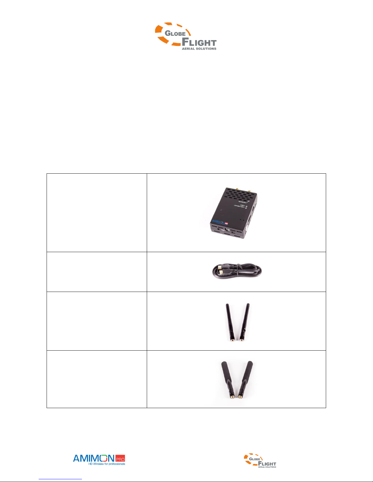
In the box .............................................................................................................................................6
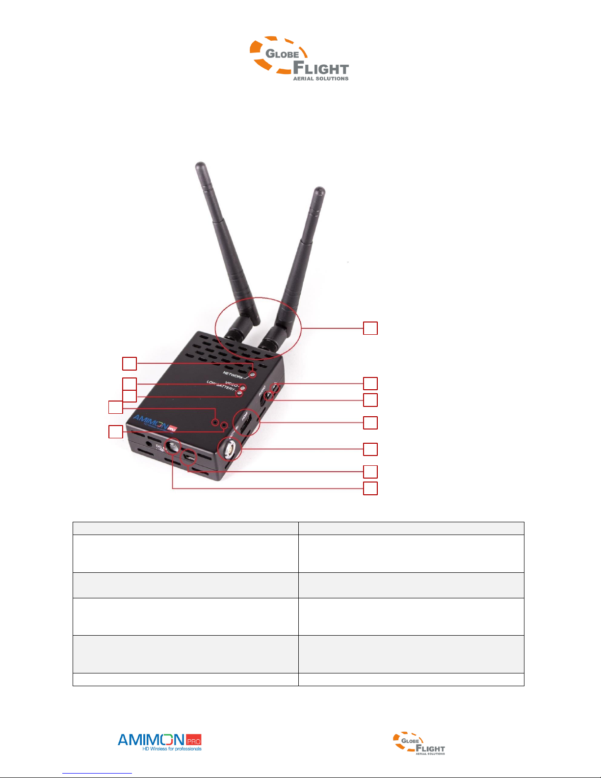
Product description ..............................................................................................................................9
The HD SkyLink Kite transmitter....................................................................................................9
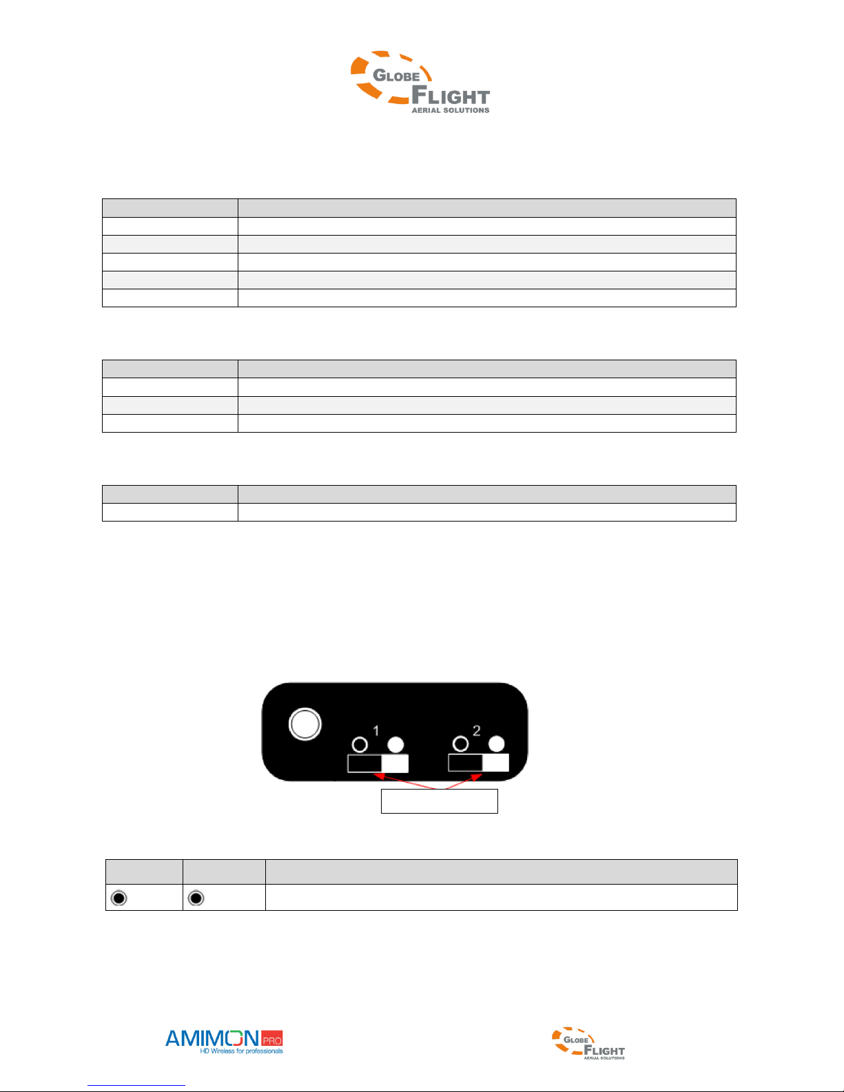
LED signals (transmitter)...............................................................................................................10
Position of the slide switches.........................................................................................................10
The HD SkyLink Falcon receiver..................................................................................................11
LED signals (receiver)...................................................................................................................12
DIP switch function........................................................................................................................12
Frequency settings..............................................................................................................................13
Installation..........................................................................................................................................17
Transmitter.....................................................................................................................................17
Receiver .........................................................................................................................................17
Infrared remote control ......................................................................................................................18
Remote control hotkeys .................................................................................................................18
Binding procedure..............................................................................................................................19
Binding one transmitter to one receiver.........................................................................................19
Binding one transmitter to multiple receivers................................................................................19
Binding multiple transmitters to one receiver................................................................................20
Removing bound transmitters........................................................................................................20
Switching between transmitters.....................................................................................................21
Supported resolution..........................................................................................................................21
OSD menu (On-Screen-Display).......................................................................................................22
Technical specifications.....................................................................................................................24
Frequently asked questions................................................................................................................26
Copyright ...........................................................................................................................................28

HD SkyLink
Manual AMIMON HD SkyLink page | 5
www.globe-flight.de
Product overview
The HD SkyLink system was designed to establish wireless HD video signal transmission without any latency
over large distances. Amimon finally made this possible with revolutionary technology!
The HD SkyLink is a lightweight but still very powerful wireless HD system, which is the perfect solution for
live streaming from your multicopter or from a steadycam system.
The HD SkyLink transmits encoded (128 AES) but uncompressed signals, broadcasting is therefore possible
without any delay (latency less than 1ms). This is the ideal live streaming equipment for sports events,
movies and TV productions.
Multicasting is supported, the signal of one transmitter can be received by multiple receivers at the same
time, which allows parallel streaming and live preview for the camera operator during recording.
You have the possibility to set the used frequencies (according to the planned usage and the frequencies
assigned by the Federal Network Agency) on location via USB port. The system allows you to have full
control and you can follow the legal regulations of your country or region.

HD SkyLink
Manual AMIMON HD SkyLink page | 6
www.globe-flight.de
In the box
Please verify that the following items are in the shipping box, prior to the installation of transmitter and
receiver.
Transmitter and accessories:
1x HD video transmitter
1x HDMI cable
(HDMI version only)
2x 2dBi omnidirectional
antennas
2x 5dBi omnidirectional
antennas

HD SkyLink
Manual AMIMON HD SkyLink page | 7
www.globe-flight.de
1x LEMO power cable
2x -9dBm attenuators
Receiver and accessories
1x HD-SDI video receiver
1x 12V Power supply
1x Cylindrical
DC power cable
5x 2dBi omnidirectional
antennas

HD SkyLink
Manual AMIMON HD SkyLink page | 8
www.globe-flight.de
5x 5dBi
omnidirectional antennas
Additional accessory:
1x Remote control
1x IR remote extension connector

HD SkyLink
Manual AMIMON HD SkyLink page | 9
www.globe-flight.de
Product description
The HD SkyLink Kite transmitter
1. Antenna connectors
7. 5V 2pin generic connector
2. Network status LED
8. MiniUSB port
The USB port can be used for firmware
updates.
3. Video status LED
9. 7-17V LEMO connector / 2 cables
Soldering option, directly to the LEMO holes
4. Low battery LED
10. HDMI or HD-SDI input port
For connecting the HD video source to
the HD SkyLink Kite transmitter
5. Registration button
For registering the transmitter to additional
receivers
11. Slide switch #1
6. Reset button
12. Slide switch #2
1
12
11
10
9
8
7
6
5
4
3
2

HD SkyLink
Manual AMIMON HD SkyLink page | 10
www.globe-flight.de
LED signals (transmitter)
Network status LED
Signal
Meaning
Solid
A connection to the receiver is established
Slow blinking
Device is in listen mode (DFS frequencies)
Normal blinking
During link setup mode
Normal blinking
During registration (after pressing the registration button)
Fast blinking
(together with the video LED) System error
Video status LED
Signal
Meaning
Solid
Video signal is being transmitted
Normal blinking
Video is not supported
Fast blinking
(together with the network LED) System error
Low battery LED
Signal
Meaning
Solid
Low battery, when voltage is less than 6.5V
Position of the slide switches
The slide switches of the HD SkyLink Kite transmitter both have to be set to the left position.
Other combinations of switch positions are not supported or have no function.
Switch #1
Switch #2
Mode
1. Standard mode (FCC, 19dBm)
Slide switches

HD SkyLink
Manual AMIMON HD SkyLink page | 11
www.globe-flight.de
The HD SkyLink Falcon receiver
1-5 External antennas
18 Binding button
6-10 Internal antennas
19 (Input voltage connector 7-17V –do not
use!)
11 XLR 4 pin power connector 7-17V
20 ON/OFF Switch
12 DFS antenna (located on the other side)
21 USB port
13 LED #4 Power
22 IR input connector
14 LED #3 Video
23 HD-SDI output
15 LED #2 Network
24 HD-SDI output
16 LED #1 Not used
25 Reset button
17 DIP switches –all switches should be up
26 Cylindrical DC power connector 7-17V
It is highly recommended NOT to use connector #19 for power supply. Even though it is shaped XH style, the
connector is not compatible with XH balancer plugs of lipo batteries. Connecting such battery with the
balancer port will destroy the ground unit. Such damage is warranty void.
We recommend to use the DC barrel plug #26
1-5
6-10
26
25
24
23
22
21
11
12
13
14
15
16
17
18
19
20

HD SkyLink
Manual AMIMON HD SkyLink page | 12
www.globe-flight.de
Pin configuration of the XLR 4 pin connector
(only the outer pins are used)
LED signals (receiver)
Network status LED
Signal
Meaning
Solid
A connection to the transmitter is established
Slow blinking
Device is in listen mode (DFS frequencies)
Normal blinking
During link setup mode
Normal blinking
During registration (after pressing the registration button)
Fast blinking
(together with the video LED) System error
Video status LED
Signal
Meaning
Solid
Video signal is being transmitted
Fast blinking
(together with the network LED) System error
Power LED
Signal
Meaning
Solid
The LED is ON when power is supplied and the ON/OFF switch is ON
DIP switch function
DIP switch no.
Function
1
Not used- should be Up
2
Not used- should be Up
3
External antenna (Up) / Internal antenna (Down)
4
Not used - should be Up
-
+

HD SkyLink
Manual AMIMON HD SkyLink page | 13
www.globe-flight.de
Frequency settings
The HD SkyLink system is flexible and easy to adjust to all different fields of use and to meet the regional
and national frequency requirements and laws.
The 5 GHz frequency band is split up into 3 different types which can be used with the HD SkyLink system,
the ISM frequencies, DSF frequencies and NON-DFS frequencies. Please view the following table to see the
different frequencies and types of usage.
Please always check the used frequency for your application and country or region. To use DFS frequencies
for remote controlled vehicles in the air, a special frequency registration at the Federal Network Agency is
required. You can find further information about the necessary steps to be taken via the following link.
Federal Network Agency
Frequency table for Europe
Frequencies in MHz
Description
Usage
5190
NON-DFS
Indoor max. 200mW EIRP
5230
NON-DFS
5270
DFS (short cac)
Indoor and outdoor
Max. 200mW EIRP
(For aerial usage, a special registration is
required)
5310
DFS (short cac)
5510
DFS (short cac)
5550
DFS (short cac)
5590
DFS (long cac)
5630
DFS (long cac)
5670
DFS (short cac)
5755
ISM; NON-DFS
Indoor, outdoor and in the air
Max. 25mW EIRP
5795
ISM; NON-DFS
5835
ISM; NON-DFS
The HD SkyLink comes with activated DFS frequencies, which make the general use indoors and outdoors
possible by default. To change the frequency settings, please follow the steps below.
1. Install the WHDI Monitor software (WHDI Monitor.exe) on your computer. Double click the file WHDI
Monitor.exe and go through the necessary steps.
2. Power up your HD SkyLink device (frequency changes have to be done both for the transmitter and the
receiver separately in the same way)
3. Connect your HD SkyLink Kite transmitter (and later the Falcon receiver) to your computer using the USB
port. Your computer will install the necessary USB drivers automatically, if the driver is not found please
install it manually from the .zip file you have downloaded.
4. Open the installed WHDI Monitor software and wait until your device is connected.

HD SkyLink
Manual AMIMON HD SkyLink page | 14
www.globe-flight.de
HD SkyLink Kite transmitter HD SkyLink Falcon receiver
5. When the connection is established, please navigate to “Tools” and choose “Frequency Selection”.

HD SkyLink
Manual AMIMON HD SkyLink page | 15
www.globe-flight.de
6. A new window with the frequency table will open. The default setting of enabled DFS frequencies can be
used for standard indoor and outdoor operation. Remember that you need a frequency registration if
you want to use the HD SkyLink system in the air.
DFS frequencies for the use on the ground indoors and
outdoors.
The use in the air is permitted with a special registration,
but only with the explicitly authorized frequencies.
7. For aerial use (without special registration), please enable the 3 ISM frequencies and use the -9dBm
attenuators to limit transmission power to 25mW EIRP. Press Update to confirm and save the frequency
selection.
ISM in Europe, 25 mW EIRP max.

HD SkyLink
Manual AMIMON HD SkyLink page | 16
www.globe-flight.de
How to use the attenuators
To limit the transmission power to 25 mW, the -9dBm attenuators simply have to be screwed on between
the two 2dBi omnidirectional antennas and the HD SkyLink Kite transmitter.
8. To use the HD SkyLink in the USA, please activate the following channels.
ISM band USA

HD SkyLink
Manual AMIMON HD SkyLink page | 17
www.globe-flight.de
Installation
Transmitter
1. Turn on the signal source.
2. Connect the HD SkyLink Kite transmitter to the HD video source.
(HDMI or HD-SDI input port #10, see the product description section)
3. Connect the HD SkyLink Kite transmitter to a power source (7-17V)
via the LEMO connector #9
4. Arrangement of the antennas: It is recommended to disperse the antennas in the shape of a "V" and
orthogonal to the line of sight between the transmitter and the receiver.
Receiver
5. Turn on the video output device, e.g. a monitor.
6. Connect the HD SkyLink Falcon receiver to the monitor using a HD-SDI cable.
(HD-SDI output port #23 / #24 or both, see the product description section)
7. Make sure that all the DIP switches are in the upper position.
(DIP switch #17, see the product description section)
8. Connect the HD SkyLink Falcon receiver to a power source (7-17V).
a. Connect the power plug to the matching input voltage connector.
(Power connector #11/#19/#26, see the product description section)
b. Slide the On/Off switch in position “1” to turn the receiver on.
9. Arrangement of the antennas: It is recommended to disperse the antennas in the shape of an open hand
and orthogonal to the line of sight between the transmitter and the receiver.
Hints to get the maximum range
Make sure that there is a line of sight between the transmitter and the receiver.
Avoid placing any unnecessary obstacles besides the transmitter or the receiver.
Mount both transmitter and receiver with the antennas pointing upwards for maximum
performance.
Mount the transmitter and the receiver with proper air ventilation.
If you use multiple receivers, keep a minimum distance of 2 meters between them.

HD SkyLink
Manual AMIMON HD SkyLink page | 18
www.globe-flight.de
1. Enter the main menu
2. Return to previous menu
3. Select video source
4. Navigation on the menu screen
(Up, down, left, right)
5. Press OK to confirm
6. Remove video source
7. Add new video source
8. Standby (receiver)
9. Connect to video source 1
10. Connect to video source 2
11. Connect to video source 3
Infrared remote control
Remote control hotkeys
The "Add" hotkey
Pressing this button starts the registration process on the receiver.
The „Delete“ hotkey
This button opens the "Remove Video Source" option in the OSD menu, which allows the
user to choose which device to remove.
The „Input Devices“ hotkeys
The buttons 1-3 switch the receiver to work with the first, second or third source as appeared on the
registered sources list.
1. Menu
2. Exit/Back
4.
Navigational
buttons
6. Remove
7. Add
9. Video
source 1
10. Video
source 2
3. Source
5. Confirm
11. Video
source 3
WHDI Remote control
8. Standby

HD SkyLink
Manual AMIMON HD SkyLink page | 19
www.globe-flight.de
Binding procedure
IMPORTANT NOTICE: In delivered condition, the transmitter and the receiver are already bound and will
connect automatically. If you only want to use this standard configuration, you can skip the following
section of the manual. The binding procedure only becomes necessary if you want to change the
configuration of the devices.
The transmitter and the receiver must be bound to establish a wireless connection. The binding process can
be started with the remote control, during the process device codes are exchanged to ensure safety.
The binding procedure is required only once. After that, the devices will connect automatically when they
are powered up.
Binding one transmitter to one receiver
If there is no transmitter connected to the receiver, a menu will appear on the screen.
1. *Connect the HD video source to the HD SkyLink Kite transmitter.
2. Connect the HD-SDI cable of the HD SkyLink Falcon receiver with the HD display.
3. Power up transmitter and receiver.
4. Take the remote control and press the „Add“ hotkey.
5. Now the following message will appear on the screen: „Please Activate the Registration on
Transmitter Unit“. The binding process must then be started on the transmitter as well.
6. Press the binding button on the transmitter and the network status LED will start blinking.
7. Wait until the following message appears on the screen: „Adding [Sendername] Press OK to
continue or Exit to cancel“.
8. Press „OK“ on the remote control to confirm the HD SkyLink Kite transmitter.
9. Wait until the binding process is completed. During the binding process, there is a status bar and
the message of step 7 („Adding…“) is still displayed.
10. The binding process is completed and a wireless video connection is established.
Note: Once the binding process was started on the receiver, 30s remain to start binding on the transmitter.
If the binding process on the transmitter was not started in time, you have to restart the binding process
with step 4.
*The binding process can be done without HD source, an OSD message will inform you about the missing video source.
Binding one transmitter to multiple receivers
The HD SkyLink Kite transmitter can be bound to up to 4 receivers at the same time.
1. At first, you need to make sure that the transmitter is not transmitting video to other receivers. All
receivers which are already bound to the transmitter should be powered down while binding to an
additional receiver.
2. Carry out steps 1-10 like in the previous section about the binding of one transmitter to one
receiver. Make sure that only the receiver to be bound is powered up.
3. Please follow steps 1 and 2 of this section to bind additional receivers.
4. After all receivers had been bound separately, all devices can be powered up at the same time. The

HD SkyLink
Manual AMIMON HD SkyLink page | 20
www.globe-flight.de
video signal should now be available on all receivers.
Binding multiple transmitters to one receiver
1. Multiple transmitters can be bound to one receiver, the desired transmitter/signal source can then
be chosen with the remote control.
2. Carry out steps 1-10 like in the previous section about the binding of one transmitter to one
receiver. Make sure that only the receiver to be bound is powered up.
Removing bound transmitters
1. Power up the HD SkyLink Falcon receiver.
2. Take the remote control of your HD SkyLink Falcon receiver and press the „Delete“ button.
3. Use the navigational buttons to choose the source to remove and confirm with „OK“.
4. Confirm that you want to remove the chosen signal source by pressing the „OK“ button , or
abort with the „Exit“ button.
5. Wait 30 seconds until the process is completed.
This manual suits for next models
1
Table of contents
Other AMIMON Transmitter manuals
Popular Transmitter manuals by other brands

Vibradorm
Vibradorm VFF/CDL-BF-07 operating instructions

Magnetrol
Magnetrol STI R95 Installation and operating manual

Endress+Hauser
Endress+Hauser HART Flowmeter Proline 400 Brief operating instructions

HumanTechnik
HumanTechnik RadioLight DIR II Operation instructions

API
API DuoPak APD 2063 quick start guide

EBS
EBS WX2NB Installation and programming manual