Amit DM-MB2ET/A User manual

dm-mb2eta_g_en_102
DM-MB2ET/A
Communication converter
M-Bus to Ethernet
Operation manual
Version 1.02

DM-MB2ET/A
dm-mb2eta_g_en_102 2/23
AMiT, spol. s r. o. does not provide any warranty concerning the contents of this
publication and reserves the right to change the documentation without
obligation to inform anyone or any authority about it.
This document can be copied and redistributed under following conditions:
1. The whole text (all pages) must be copied without any changes.
2. All redistributed copies must retain the AMiT, spol. s r. o. copyright notice
and any other notices contained in the documentation.
3. This document must not be distributed for purpose of making profit.
The names of products and companies used herein can be trademarks or
registered trademarks of their respective owners.
AMiT is a registered trademark.
Copyright (c) 2017, AMiT, spol. s r. o.
Producer: AMiT, spol. s r. o.
Naskové 1100/3, 150 00 Praha
www.amitomation.com

DM-MB2ET/A
3/23 dm-mb2eta_g_en_102
Contents History of revisions.........................................................................................4
Related documentation...................................................................................4
1Introduction..........................................................................................5
2Technical parameters..........................................................................6
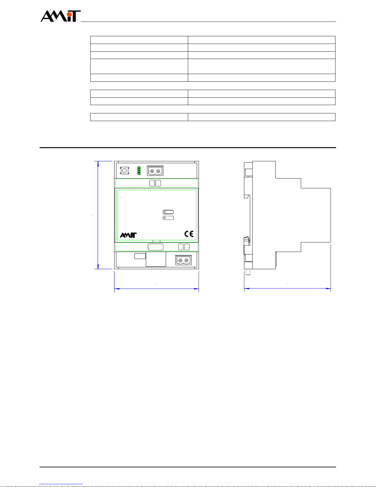
2.1 Dimensions.....................................................................................................7
2.2 Recommended drawing symbol .....................................................................8
3Conformity assessment ......................................................................9
3.1 Other tests....................................................................................................10
4Power supply......................................................................................11
5Communication interfaces................................................................13
5.1 M-Bus interface ............................................................................................13
5.2 Ethernet interface.........................................................................................14
6Mounting.............................................................................................17
6.1 Installation rules............................................................................................17
7Converter configuration....................................................................18
7.1 Service button...............................................................................................18
7.2 LED RUN......................................................................................................18
7.3 Service mode................................................................................................19
8Factory settings .................................................................................20
Ethernet factory settings...............................................................................20
M-Bus factory settings..................................................................................20
8.1 Factory settings restoring .............................................................................20
9Ordering information and Package contents..................................21
9.1 Package contents.........................................................................................21
10 Maintenance .......................................................................................22
11 Waste disposal...................................................................................23

DM-MB2ET/A
dm-mb2eta_g_en_102 4/23
History of revisions
Document name: dm-mb2eta_g_en_102.pdf
Revision
Date
Author of change
Changes
100
05. 04. 2011
Csörgő V.
New document.
101
23. 06. 2011
Csörgő V.
Correction of operating range -25 °C to 50 °C.
102
30. 05. 2017
Říha Z.
Change in chapter 1, 2, added figures, change of manual
structure.
Related documentation
1. DM-MB2ET/A –Software in converter DM-MB2ET/A –Programmers guide
file: dm-mb2eta_ms_en_xxx.pdf
2. Application Note AP0010 –Communication in M-Bus Network
file: ap0010_en_xx.pdf
3. Application Note AP0008 –Communication in MODBUS Network
file: ap0008_en_xx.pdf
4. Application Note AP0037 –Principles of Ethernet network usage
file: ap0037_en_xx.pdf

DM-MB2ET/A
5/23 dm-mb2eta_g_en_102
1 Introduction
DM-MB2ET/A is M-Bus communication converter to Ethernet.
MASTER-type M-Bus interface, up to 3 SLAVE-type units
Ethernet interface 10/100 Mbps (communication MODBUS/TCP, APE,
Direct)
Power supply +24 V DC or PoE
Mounting on a rail DIN 35 mm
The communication MODBUS/TCP allows up to 6 clients to be connected.
Basic
features
Note

DM-MB2ET/A
dm-mb2eta_g_en_102 6/23
2 Technical parameters
CPU
STM32F107VCT6
FLASH
256 KB
SRAM
64 KB
Quantity
1
Communication speed
10/100 Mbps
Galvanic isolation
Yes
Insulation strength
500 V AC / 1 minute 1)
Operation indication
LED on mainboard
Connection point
Connector RJ45, according to IEEE802.3
1) Insulation must not be used for dangerous voltage separation.
Quantity
1
Interface type
MASTER
Transmission speed
150 bps to 9600 bps
Overvoltage protection
Transil 600 W
Interface short-circuits protection
Resettable thermal fuse 100 mA
M-bus interface power supply
From internal power supply
Galvanic isolation
No
Number of connectable units
1 to 3, SLAVE-type
Operation indication
LED on mainboard
Connection point
WAGO 231-302/102-000
Wire cross section
0.08 mm2to 2.5 mm2
Nominal power supply voltage
24 V DC
Power supply voltage range
19.2 V DC to 28.8 V DC
Maximum power consumption
210 mA at 24 V DC
Power dissipation (typical)
2.5 W
Galvanic isolation
Yes 2)
Insulation strength
500 V AC / 1 minute 3)
Connection point
WAGO 231-302/102-000
Wire cross section
0.75 mm2to 2.5 mm2
Power supply system
Device must not be power supplied from DC
distribution network of building 4)
2) Galvanically isolated from the internal electronics.
3) Insulation must not be used for dangerous voltage separation.
4) For detailed information, see the chapter “6.1 Installation rules” paragraph
“Power supply”.
Nominal power supply voltage
48 V DC
Power supply voltage range
43.2 V DC to 52.8 V DC
Maximum power consumption
70 mA at 48 V DC
Galvanic isolation
Yes 5)
Insulation strength
500 V AC / 1 minute 6)
Connection point
Connector RJ45 (for Ethernet connection)
5) Galvanically isolated from the internal electronics.
6) Isolation must not be used for dangerous voltage separation.
Communication
CPU
Ethernet
Note
M-Bus
Power supply
24 V DC
Note
Power supply
PoE
Note

DM-MB2ET/A
7/23 dm-mb2eta_g_en_102
Mechanical design
Plastic box
Mounting
On DIN rail 35 mm
Ingress protection rate
IP20
Weight –netto
–brutto
0.16 kg ±5 %
0.22 kg ±5 %
Dimensions (w × h × d)
(71 × 90 × 73) mm
Operating temperature range
-25 °C to 50 °C
Storage temperature range
-25 °C to 50 °C
Maximum ambient humidity
< 95 % non-condensing
2.1 Dimensions
PWR
21
MBUS MBUS
RUN
DM-MB2ET/A
ETHERNET
4
3
GND+24V
90
71 73
Fig. 1 –DM-MB2ET/A dimensions
Mechanics
Temperatures
Others

DM-MB2ET/A
dm-mb2eta_g_en_102 8/23
2.2 Recommended drawing symbol
Following drawing symbol is recommended for the communication converter
DM-MB2ET/A. Only part of it will be visible in following examples.
M-Bus
4
DM-MB2ET/A
1
2
MBUS
MBUS
+24V
Ethernet
PWR
GND
3
Ethernet s PoE
RJ45
Fig. 2 –Recommended drawing symbol for DM-MB2ET/A

DM-MB2ET/A
9/23 dm-mb2eta_g_en_102
3 Conformity assessment
The equipment meets the requirements of NV616/2006 Czech Government
Decree. The compliance assessment with NV616/2006 has been performed in
accordance with harmonized standard EN 61326-1:2013.
Tested in accordance
with standard
Type of test
Class
EN 55011:2009
Industrial, scientific and medical
equipment –Radio-frequency
disturbance characteristics –Limits and
methods of measurement
Complies,
A 7)
EN 61000-4-2:2009
Electromagnetic compatibility (EMC) –
Part 4-2: Testing and measurement
techniques –Indirect electrostatic
discharge immunity test, contact
discharge
Complies
(±8 kV)
EN 61000-4-2:2009
Electromagnetic compatibility (EMC) –
Part 4-2: Testing and measurement
techniques –Indirect electrostatic
discharge immunity test, air discharge
Complies
(±16 kV)
EN 61000-4-3:2006
Electromagnetic compatibility (EMC) –
Part 4-3: Testing and measurement
techniques –Radiated, radio-frequency,
electromagnetic field immunity test
80 MHz to 1 GHz
Complies
(10 V/m)
EN 61000-4-3:2006
Electromagnetic compatibility (EMC) –
Part 4-3: Testing and measurement
techniques –Radiated, radio-frequency,
electromagnetic field immunity test
1.4 GHz to 2 GHz
Complies
(10 V/m)
EN 61000-4-3:2006
Electromagnetic compatibility (EMC) –
Part 4-3: Testing and measurement
techniques –Radiated, radio-frequency,
electromagnetic field immunity test
2 GHz to 1.7 GHz
Complies
(3 V/m)
EN 61000-4-4:2012
Electromagnetic compatibility (EMC) –
Part 4-4: Testing and measurement
techniques –Electrical fast
transient/burst immunity test, power
supply, Ethernet, M-Bus
Complies
(4 kV)
EN 61000-4-5:2006
Electromagnetic compatibility (EMC) –
Part 4-5: Testing and measurement
techniques –Surge immunity test, power
supply, M-Bus shielding
Complies
(3 kV)
EN 61000-4-5:2006
Electromagnetic compatibility (EMC) –
Part 4-5: Testing and measurement
techniques –Surge immunity test,
Ethernet shielding
Complies
(4 kV)

DM-MB2ET/A
dm-mb2eta_g_en_102 10/23
Tested in accordance
with standard
Type of test
Class
EN 61000-4-6:2009
Electromagnetic compatibility (EMC) –
Part 4-6: Testing and measurement
techniques –Immunity to conducted
disturbances, induced by radio-frequency
fields
Complies
(10 V)
7) This is a class A device. This device can cause some radio disturbances in
the internal environment. In such case, the user can be requested to take
the appropriate measures.
3.1 Other tests
Tested in accordance
with standard
Type of test
Classification
EN 60068-2-1:2007
Environmental testing –Part 2-1: Tests –
Test A: Cold
Complies
EN 60068-2-2:2007
Environmental testing –Part 2-2: Tests –
Test B: Dry heat
Complies
EN 61000-4-29:2000
Electromagnetic compatibility (EMC) –
Part 4-29: Testing and measurement
techniques –Voltage dips, short
interruptions and voltage variations on
DC input power port –Immunity test
Complies
Note

DM-MB2ET/A
11/23 dm-mb2eta_g_en_102
4 Power supply
The communication converter DM-MB2ET/A can be power supplied by DC
power supply or Ethernet (PoE). The power supply must meet requirements
mentioned in the chapter “2 Technical parameters”.
Connection of power supply voltage is indicated by LED PWR.
PWR
21
MBUS MBUS
RUN
DM-MB2ET/A
ETHERNET
4
3
GND+24V
23
1
Fig. 3 –Power supply connector +24 V DC
Number
Description
1
LED PWR
2
Connector for Ethernet with PoE
3
Connector for power supply 24 V DC
Terminal
Signal
Description
3
GND
Power supply, ground
4
+24V
Power supply, +24 V DC
LED
Description
Lit
Power supply is connected
Not lit
Power supply is not connected
Legend
Terminals
marking
LED states
description

DM-MB2ET/A
dm-mb2eta_g_en_102 12/23
+ 24 V
GND
1
M-Bus
4
DM-MB2ET/A
1
2
MBUS
MBUS
+24V
Ethernet
PWR
GND
3
Ethernet s PoE
RJ45
Fig. 4 –Example of power suppling from power supply +24 V DC
Number
Description
1
External power supply 24 V DC
It is recommended to connect the GND terminals with switchboard PE terminal
during installation.
The communication converter can be power supplied by PoE. For this power
supply, e.g. standard PoE switches from AMiT production can be used.
M-Bus
4
DM-MB2ET/A
1
2
MBUS
MBUS
+24V
Ethernet
PWR
GND
3
Ethernet s PoE
RJ45
ESW06A
PWR
PE
G
V+
X7
1
2
3
RJ45
RJ45
RJ45
RJ45
RJ45
RJ45
X5
PoE
X2
Poe
X6
PoE
X3
PoE
X4
PoE
X1
UPLINK
Fig. 5 –Example of power supplying from power supply PoE
Wiring
example
Legend
Note
Power supply
PoE
Wiring
example

DM-MB2ET/A
13/23 dm-mb2eta_g_en_102
5 Communication interfaces
The communication converter DM-MB2ET/A has two communication interfaces:
M-Bus interface,
Ethernet interface.
5.1 M-Bus interface
The communication converter DM-MB2ET/A works on M-Bus interface as
MASTER. The device supports up to 3 SLAVE-type stations on M-Bus
interface.
M-Bus interface activity is indicated by LEDs on the mainboard.
PWR
21
MBUS MBUS
RUN
DM-MB2ET/A
ETHERNET
4
3
GND+24V
2
1
Fig. 6 –Location of LEDs and terminals for M-Bus
Number
Description
1
Status LEDs
2
Terminals for M-Bus
Terminal
Signal
Description
1
MBUS
Terminal for M-Bus interface
2
MBUS
Terminal for M-Bus interface
LED
Description
MBUS Rx
Converter is receiving data
MBUS Tx
Converter is transmitting data
Legend
Terminals
marking
LEDs
description

DM-MB2ET/A
dm-mb2eta_g_en_102 14/23
M-Bus interface is galvanically separated from power supply +24 V and from
power supply PoE. M-Bus interface is not galvanically separated from internal
electronics.
1
M-Bus
4
DM-MB2ET/A
1
2
MBUS
MBUS
+24V
Ethernet
PWR
GND
3
Ethernet s PoE
RJ45
M-Bus
M-Bus
Fig. 7 –Wiring example of M-Bus interface
Number
Description
1
Periphery (slave) in network M-Bus
More information about M-Bus interface connection can be found in Application
Note AP0010 –Communication in M-Bus Network.
5.2 Ethernet interface
Speed 10/100 Mbps
Half-duplex or Full-duplex support
Direct and crossover cable support
Interface state indication by LED LINK and LED ACT
Ethernet interface activity is indicated by LEDs on the mainboard.
Note
Wiring
example
Legend

DM-MB2ET/A
15/23 dm-mb2eta_g_en_102
PWR
21
MBUS MBUS
RUN
DM-MB2ET/A
ETHERNET
4
3
GND+24V
2
1
Fig. 8 –Location of LEDs and connector for Ethernet
Number
Description
1
Status LEDs
2
Connector for Ethernet
The order of connector RJ 45 PINs is shown in the following figure.
Fig. 9 –Order of RJ45 connector PINs
Pin
Signal
Description
1
Tx+ / PoE A
Signal Tx+ / wire for PoE switch
2
Tx- / PoE A
Signal Tx- / wire for PoE switch
3
Rx+ / PoE A
Signal Rx+ / wire for PoE switch
4
+48V PoE B
Power supply PoE +48 V
5
+48V PoE B
Power supply PoE +48 V
6
Rx- / PoE A
Signal Rx- / wire for PoE switch
7
0V PoE B
Power supply PoE 0 V
8
0V PoE B
Power supply PoE 0 V
Legend
Ethernet
connector
wiring

DM-MB2ET/A
dm-mb2eta_g_en_102 16/23
LED
Description
ETH ACT
Communication takes place on Ethernet interface
ETH LNK
Established connection on Ethernet interface
More information about Ethernet interface connection can be found in
Application Note AP0037 –Principles of Ethernet network usage.
LEDs
description

DM-MB2ET/A
17/23 dm-mb2eta_g_en_102
6 Mounting
The communication converter DM-MB2ET/A must be mounted in
the switchboard. It is intended for mounting on DIN rail 35 mm.
6.1 Installation rules
The equipment must not be power supplied from DC distribution network of
building. More equipment can be power supplied from a single power supply
assuming the similar-type equipment and the same building location.
It is recommended to connect the GND terminals with switchboard PE terminal
during installation.
It is necessary to use 2-wire cable with the shielding for M-Bus interface
connection. The cable must not be longer than 30 m and must not come out of
building. Connect the cable shielding to the PE terminal immediately on
switchboard input. The cable FTP or STP is recommended, two pairs will create
one M-Bus input.
Ethernet interface can be connected through a cabling Cat5 with the shielding.
All PE terminal connections must be realized with the lowest impedance as
possible. The technical parameters of communication converter are guaranteed
only, when these wiring principles are applied.
All cables, leading to the communication converter, must be pulled through
a filter ferrite. The ferrites must be placed as closed as possible to
the converted. Two cables can be pulled through one ferrite filter. The ferrites
must be used because of radio interference. If they are not used,
the manufacturer does not provide the guaranteed radiation parameters.
Recommended ferrites are listed in ordering information.
M-Bus
4
DM-MB2ET/A
1
2
MBUS
MBUS
+24V
Ethernet
PWR
GND
3
Ethernet s PoE
RJ45
F_FILTR/A07 F_FILTR/A07
Fig. 10 –Ferrite filters wiring on the cables
Power supply
Connecting
to PE
M-Bus
Ethernet
Note
Filtration

DM-MB2ET/A
dm-mb2eta_g_en_102 18/23
7 Converter configuration
It is necessary to switch the converter to service mode for converter
communication. The converter can be switched to service mode using a service
button.
7.1 Service button
The service button is located in upper left corner of converter.
PWR
21
MBUS MBUS
RUN
DM-MB2ET/A
ETHERNET
4
3
GND+24V
1
Fig. 11 –Service button location
Number
Description
1
Service button
7.2 LED RUN
The converter state is indicated by LED RUN.
Legend

DM-MB2ET/A
19/23 dm-mb2eta_g_en_102
PWR
21
MBUS MBUS
RUN
DM-MB2ET/A
ETHERNET
4
3
GND+24V
1
Fig. 12 –LED RUN location
Number
Description
1
LED RUN
LED
Description
Flashing with period 0.5 s
Converter is in service mode.
Flashing, period 2 s
Converter is in application mode (standard operation).
Lit
Converter has switched to factory settings.
7.3 Service mode
It is possible to change the device communication parameters in service mode.
Details regarding individual parameters setting are mentioned in
the programmer manual dm-mb2et_ms_en_xxx.pdf.
The converter can be switched to service mode, as follows:
Disconnect DM-MB2ET/A from the power supply voltage.
Connect the power supply voltage while holding the service button.
Hold the button for 5 s, then release. LED RUN is flashing with the period
0.5 s (the button must be pressed within 10 s, otherwise DM-MB2ET/A will
pass into the factory setting).
Device settings are performed using a web interface. It is necessary to turn
the device off and on for its launching with a new setting.
Legend
LED
description

DM-MB2ET/A
dm-mb2eta_g_en_102 20/23
8 Factory settings
Ethernet factory settings
Parameter
Default value
Converter IP address
192.168.1.1
Network mask
255.255.0.0
Default gateway
192.168.1.254
DHCP
Activated
M-Bus factory settings
Parameter
Default value
Port M-Bus
2000
M-Bus communication speed
2400 bps
Mode
1 –Direct
Direct timeout
500
8.1 Factory settings restoring
Factory settings can be restored using the service button (see the chapter
“7.1 Service button”).
Disconnect DM-MB2ET/A from the power supply voltage.
Connect the power supply voltage while holding the service button.
Hold the button for at least 10 s (until LED RUN will not light permanently),
then release the button.
Disconnect and connect the power supply voltage of converter.
DHCP settings cannot be switched to the factory settings! DHCP factory
settings cannot be restored after manual settings change. The parameter can
only be changed manually (see the programmers guide
dm-mb2et_ms_en_xxx.pdf).
Restoring
procedure
Attention
Table of contents