IDK NJR-T01SDI Operating manual

AV over IP Encoder for SDI
NJR-T01SDI
<Command Reference Guide>
Ver.1.0.0
Thank you for choosing our product.
To ensure the best performance of this product, please read this user guide fully and carefully before
using it and keep this manual together with the product for future reference as needed.
IDK Corporation

NJR-T01SDI Command Guide
2
Trademarks
The terms HDMI and HDMI High-Definition Multimedia Interface, and the HDMI Logo are trademarks or
registered trademarks of HDMI Licensing Administrator, Inc. in the United States and other countries.
IP NINJAR is a registered trademark of IDK Corporation in Japan.
All other company and product names mentioned in this manual are either registered trademarks or
trademarks of their respective owners. In this manual, the “®” or “™” marks may not be specified.

NJR-T01SDI Command Guide
3
Before reading this manual
All rights reserved.
Some information contained in this Command guide such as exact product appearance, diagrams, menu
operations, communication commands, and so on may differ depending on the product version.
This Command guide is subject to change without notice. You can download the latest version from IDK’s
website at: http://www.idkav.com
The reference manual consists of the following two volumes:
■User guide (this document):
Provides explanations and procedures for operations, installation, connections among devices, I/O
adjustment and settings.
■Command guide: Please download the command guide from the website above.
Provides explanations and procedures for external control using RS-232C and LAN communications.

NJR-T01SDI Command Guide
4
Table of Contents
1How to read this Guide .............................................................................................................................. 5
2About this Guide ........................................................................................................................................ 6
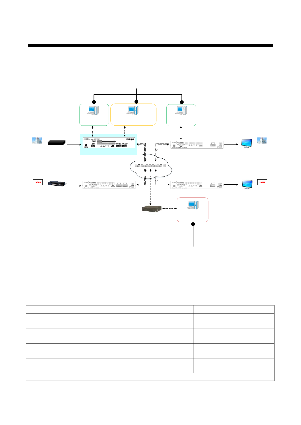
3Communication configuration and Specifications...................................................................................... 7
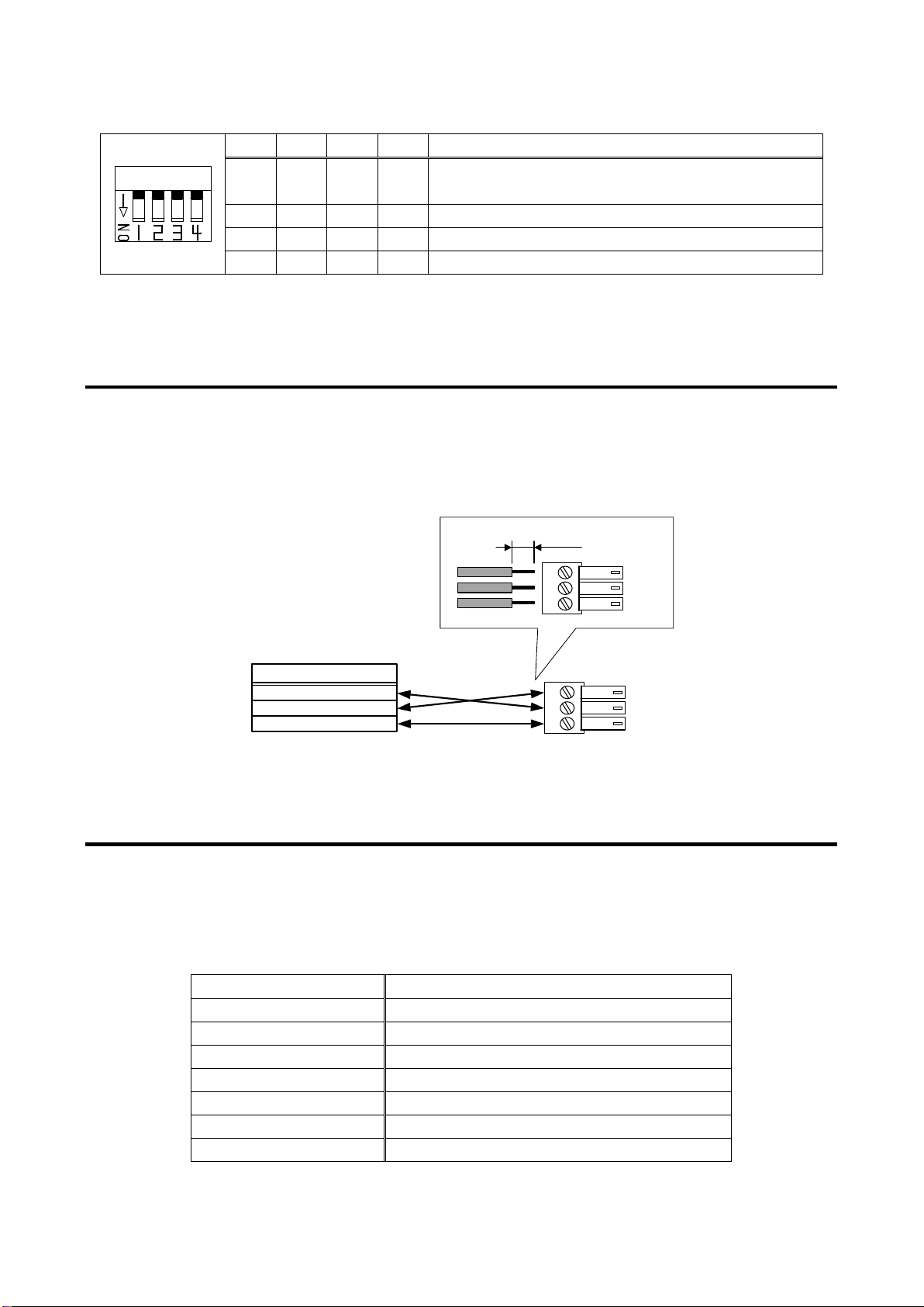
3.1 RS-232C communication...................................................................................................................... 7
3.1.1Setup of RS-232C communication................................................................................................ 7
3.1.2 RS-232C connector specification.................................................................................................. 8
3.1.3 RS-232C communication specification ......................................................................................... 8
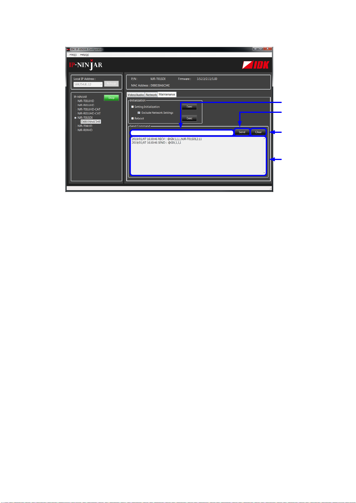
3.2 LAN communication.............................................................................................................................. 9
3.2.1 Setup LAN communication............................................................................................................ 9
3.2.2 LAN connector specification........................................................................................................ 11
3.2.3 LAN communication specification............................................................................................... 11
3.3 External control from NJR-CTB.......................................................................................................... 12
3.4 Connecting LAN cable........................................................................................................................ 12
4Command................................................................................................................................................. 13
4.1 Summary............................................................................................................................................. 13
4.2 Command list...................................................................................................................................... 14
4.3 Setting items....................................................................................................................................... 15
4.4 Parameter input format....................................................................................................................... 16
4.5 Details of commands .......................................................................................................................... 17
4.5.1 Error status.................................................................................................................................. 17
4.5.2 Basic settings.............................................................................................................................. 18
4.5.2.1 Output settings.................................................................................................................... 18
4.5.2.2 Audio................................................................................................................................... 21
4.5.2.3 Input settings ...................................................................................................................... 22
4.5.2.4 RS-232C settings................................................................................................................ 24
4.5.2.5 LAN settings ....................................................................................................................... 25
4.5.2.6 Other settings ..................................................................................................................... 27
4.5.2.7 Information.......................................................................................................................... 28

NJR-T01SDI Command Guide
5
1 How to read this Guide
This guide contains the procedure for commanding NJR-T01SDI via RS-232C communication or LAN
communication.
For other products of IP-NINJAR series, see [Table 1.1] Document for IP-NINJAR products.
IP network
Cable for entension
Source device
SDI
NJR-T01SDI (Encoder)IP-NINJAR series decoders
HDMI
IP-NINJAR series decoders
HDMI
Monitor
Monitor
PC for control
(For NJR-CTB)
LAN
LAN
Control box
(NJR-CTB)
PC for control
(For communication
command)
RS-232C
PC for control
(For communication
command)
RS-232C
1080p1080p
1080p
Chapter 2 to 4
PC for control
(For IP-NINJAR Configurator)
LAN
10 GbE switch
Source device
HDMI
IP-NINJAR series encoders
1080p
Chapter 2 to 4
(NJR-CTB Command Guide)
[Fig. 1.1] Document structure
[Table 1.1] Document for IP-NINJAR products
Model User Guide Command Guide
NJR-T01SDI NJR-T01SDI
User Guide
NJR-T01SDI
Command Guide
NJR-T01UHD / NJR-R01UHD
User Guide
NJR-T01UHD / NJR-R01UHD
Command Guide
NJR-T04HD / NJR-R04HD NJR-T04HD / NJR-R04HD
User Guide
NJR-T04HD / NJR-R04HD
Command Guide
NJR-CTB NJR-CTB
User Guide
NJR-CTB
Command Guide
IP-NINJAR Configurator
IP-NINJAR Configurator User Guide

NJR-T01SDI Command Guide
6
2 About this Guide
This guide contains the procedure for controlling NJR-T01SDI using commands via RS-232C communication
or LAN communication.
■Communication commands enables the following main operations:
・Setting input, output
・Setting audio
・Displaying information

NJR-T01SDI Command Guide
7
3 Communication configuration and Specifications
3.1 RS-232C communication
The NJR-T01SDI can be accessed and controlled via RS-232C communication.
Connecting a control device to the NJR-T01SDI’s RS-232C connectors enables system control and status
queries per the Command List.
3.1.1 Setup of RS-232C communication
Follow the procedure below.
PC for control
(1)
Cable connection
(2)
Communication
setting
(4)
Communication
command
* NJR-T01SDI can not be controlled from a PC connected to IP-NINJAR series decoders.
RS-232C connectorDIP switch
Cable for
extension
IP-NINJAR series
decoders
NJR-T01SDI (Encoder)
Audio D*1
DIP switch
Video/audio D*1
Audio A*2
Group A
D/A conversion
A/D conversion
TX
CPU
SDI receiver
CPU
HDMI transmitter
Cable driver
AUDIO INPUT RS-232CLAN
SDI OUTPUTAUDIO OUTPUT HDMI OUTPUT
SDI INPUT
Group B
(3)
Selecting command group
Scan
converter
Video
*1
Audio D: Digital audio
*2
Audio A: Analog audio
Video/audio D
*1
Video/audio D*1
[Fig. 3.1] RS-232C communication setup
(1) Connect the control device to the RS-232C connector of the NJR-T01SDI through an RS-232C cable.
(2) See the control device according to “[Table 3.2] RS-232C specification”.
(3) Set the DIP switch of the NJR-T01SDI to Group A or Group B depending on the communication command
you use. (“[Table 3.1] DIP switch”).
【See: 4.2 Command list】
(4) Send communication command from the control device to the NJR-T01SDI.
You can control the NJR-T01SDI and get the status information using communication command.

NJR-T01SDI Command Guide
8
[Table 3.1] DIP switch
1
2
3
4
Description
OFF OFF -* -* Connecting to IP-NINJAR decoder (RS-232C
connector) by default
ON
OFF
-
*
-
*
Command group A
OFF
ON
-
*
-
*
Setting disabled
ON
ON
-
*
-
*
Command group B
*-: No Connection
3.1.2 RS-232C connector specification
The NJR’s RS-232C connection is supported by a 3-position terminal block.
Insert and secure the wires from the RS-232C cable into the supplied 3-position terminal block, and then
insert the terminal block into to the mating connector on the NJR-T01SDI.
AWG28 to AWG16 conductor gauge is recommended. The recommended wire strip length is 0.28 in. (7 mm).
Short RTS/CTS and DTR/DSR as needed.
Tx
Rx
GND
Up to 0.28" (7mm)
Control device
Tx
Rx
GND
NJR-T01SDI
RxD
TxD
GND
Signal
(Receiving data)
(Sending data)
(Ground)
[Fig. 3.2] Connecting RS-232C cable to 3-pin terminal block connector
3.1.3 RS-232C communication specification
There are two RS-232C modes: control mode (setting NJR) and communication mode (controlling peripheral
devices). Values for the former mode are fixed as mentioned in the table below and cannot be changed;
values for the latter mode are settable.
【See: 4.5.2.4 RS-232C settings】
[Table 3.2] RS-232C specification
Compliant standard RS-232C
Baud rate 9600 [bps]
Data bit 8 [bit]
Parity check
None
Stop bit
1 [bit]
X parameter
Invalid
Flow control
None
Communication method
Full duplex

NJR-T01SDI Command Guide
9
3.2 LAN communication
The NJR-T01SDI can be accessed and controlled through LAN communication.
Connecting a control device to the NJR-T01SDI’s LAN connector enables system control and status queries
using the IP-NINJAR Configurator (configuration software for IP-NINJAR).
For operations from the IP-NINJAR Configurator, refer to the User Guide of IP-NINJAR Configurator.
The IP-NINJAR Configurator can be downloaded from
http://www.idkav.com
Note:
When using LAN communication to control the NJR-T01SDI, the terminal software cannot be used.
3.2.1 Setup LAN communication
Follow the procedure below.
(1) Connect the control device to the LAN connector of the NJR-T01SDI through a LAN cable.
(2) Start the IP-NINJAR Configurator in the control device.
(3) Send communication command from the Maintenance page of the IP-NINJAR Configurator.
You can control the NJR-T01SDI and get the status information using communication command.
PC for control
(1)
Cable connection
(2)
IP-NINJAR Configurator
(3)
Communication command * PCs can control both NJR-T01SDI and IP-NINJAR series decoders by connecting to
either NJR-T01SDI or IP-NINJAR series decoders.
LAN connector
IP-NINJAR series
decoders
Cable for
extension
NJR-T01SDI (Encoder)
Audio D
*1
DIP switch
Video/audio D
*1
Audio A
*2
Group A
D/A conversion
A/D conversion
TX
CPU
SDI receiver
CPU
HDMI transmitter
Cable driver
AUDIO INPUT RS-232CLAN
SDI OUTPUTAUDIO OUTPUT HDMI OUTPUT
SDI INPUT
Group B
Scan
converter
Video
Video/audio D
*1
Video/audio D
*1
*1
Audio D: Digital audio
*2
Audio A: Analog audio
[Fig. 3.3] LAN communication setup

NJR-T01SDI Command Guide
10
①For entering the desired command.
②For sending the command to NJR-T01SDI or IP-NINJAR series decoders.
④For deleting the log.
③For displaying the log.
①
②
④
③
[Fig. 3.4] Command input from Maintenance page

NJR-T01SDI Command Guide
11
3.2.2 LAN connector specification
Pin assignment of the LAN connector is as follows.
Since Auto MDI / MDI-X that distinguishes and switches straight/cross cables automatically is supported,
extra care is not necessary to connect the NJR-T01SDI to PC, HUB or the like.
18
8-pin RJ-45
Modular connector
* N.C.: No Connection
[Fig. 3.5] LAN connector
3.2.3 LAN communication specification
[Table 3.3] LAN communication
Physical layer 10Base-T (IEEE802.3i) / 100Base-TX (IEEE802.3u) /
1000Base-T (IEEE802.3ab)
Network layer
ARP, IP, ICMP
Transport layer
UDP
Pin
number
Signal name
MDI MDI-X
1000BASE-T 100BASE-TX/10BASE-T 1000BASE-T 100BASE-TX/10BASE-T
1 TRX+ (Transmitted &
Received data+)
TX+ (Transmitted data+) TRX+ (Transmitted &
Received data+)
RX+ (Received data+)
2 TRX- (Transmitted &
Received data)
TX- (Transmitted data) TRX- (Transmitted &
Received data)
RX- (Received data)
3 TRX+ (Transmitted &
Received data+)
RX+ (Received data+) TRX+ (Transmitted &
Received data+)
TX+ (Transmitted data+)
4 TRX+ (Transmitted &
Received data+)
N.C. (No connection) TRX+ (Transmitted &
Received data+)
N.C. (No connection)
5 TRX- (Transmitted &
Received data)
N.C. (No connection) TRX- (Transmitted &
Received data)
N.C. (No connection)
6 TRX- (Transmitted &
Received data)
RX- (Received data) TRX- (Transmitted &
Received data)
TX- (Transmitted data)
7 TRX+ (Transmitted &
Received data+)
N.C. (No connection) TRX+ (Transmitted &
Received data+)
N.C. (No connection)
8 TRX- (Transmitted &
Received data)
N.C. (No connection) TRX- (Transmitted &
Received data)
N.C. (No connection)

NJR-T01SDI Command Guide
12
3.3 External control from NJR-CTB
Connecting a control device to the NJR-CTB’s LAN connector enables system control and status queries per
the Command List.
For operations from the NJR-CTB, refer to the Command Guide of NJR-CTB.
MAINTENANCE connector
Tablet
MAINTENANCE
NJR-CTB
PC for control
LAN cable
*2
Communication
command
TCP: 1100
Command
server
WEB
server
Browser
HTTP: 80
LAN
LAN connector
HUB
LAN cable
*1
10 GbE switch
Cable for
extension
NJR-T01SDINJR-CTB
NJR-T01SDI
The LAN connector of NJR-CTB should be connected to the LAN connector of IP-NINJAR products or the 10 GbE switch.
*1
PC for control should be connected to the MAINTENANCE connector of NJR-CTB or the LAN connector of IP-NINJAR products.
*2
NJR-T01SDI
IP-NINJAR series decoders
Cable for
extension
LAN connector
[Fig. 3.6] Connecting to NJR-CTB
3.4 Connecting LAN cable
When connecting a LAN cable to NJR-T01SDI / NJR-CTB, avoid making a network loop.
The NJR-T01SDI sends broadcast packets periodically for the purposes of internal system management.
*A broadcast storm occurs when a network is overwhelmed by continuous broadcast traffic resulting in a
network meltdown.
During installation, it is important to avoid the creation of network loops. Contact IDK if you require assistance
with network implementation.

NJR-T01SDI Command Guide
13
4 Command
4.1 Summary
A command consists of “@” (“40” in hexadecimal), 3 or 4 one-byte alphabetical characters (upper and lower
cases) followed by parameters (one-byte numbers). For some commands, multiple parameter values can be
specified. Processing is executed by sending a delimiter at the end of the command.
Example: @GIV,1,1,1
“,” (a comma, “2C” in hex) is indicated between a command and parameter and between two parameters.
“ ” is indicated as a delimiter CR LF (return+line feed, “0D” and “0A” in hex).
■If an error occurs:
An error response is returned if an undefined command or inappropriate parameter is included.
Example: @XYZ,1
@ERR,2

NJR-T01SDI Command Guide
14
4.2 Command list
■Error status
Command Function Group A Group B Page
@ERR
Error status
Supported
Supported
17
■Output settings
Command Function Group A Group B Page
@GDM / @SDM Output mode Supported N/A 18
@GDI / @SDI Output deep color Supported N/A 19
@GHM / @SHM Hot plug masking Supported N/A 20
■Audio
Command Function Group A Group B Page
@GAM / @SAM Digital audio output mute Supported
N/A
21
■Input settings
Command
Function
Group A
Group B
Page
@GAG / @SAG
SDI input audio group
N/A
Supported
22
@GDU / @SDU
SDI Dual Stream input video
N/A
Supported
23
■RS-232C settings
Command Function Group A Group B Page
@GCTB / @SCTB
RS-232C communication setting
N/A
N/A
24
■LAN settings
Command Function Group A Group B Page
@GIP / @SIP LAN setting N/A N/A 25
@GMC MAC address N/A N/A 26
■Other settings
Command
Function
Group A
Group B
Page
@CLRC
Initialization
N/A
N/A
27
@RBTC Reboot N/A
N/A
27
■Information
Command
Function
Group A
Group B
Page
@GQV
Input video status
N/A
Supported
28
@GQA
Input audio status
N/A
Supported
30
@GSS
I/O status
Supported
N/A
31
@GES
Monitor EDID
Supported
N/A
34
@GIV
Version
Supported
N/A
35

NJR-T01SDI Command Guide
15
4.3 Setting items
Some setting items can be controlled via commands/GUI operation; the others cannot be controlled.
[Table 4.1] Available setting method
Command: Command input, GUI: GUI operation, WEB&C: WEB browser and command input, No: Not supported, -: N/A
Command
Setting method
RS-232C LAN
(IP-NINJAR
Configurator)
LAN
(NJR-CTB)
Output settings
@GDM / @SDM Command Command WEB&C
@GDI / @SDI Command Command WEB&C
@GHM / @SHM Command Command WEB&C
Audio
@GAM / @SAM
Command
Command
WEB&C
Input settings
@GAG / @SAG
Command
Command
WEB&C
@GDU / @SDU
Command
Command
WEB&C
RS-232C settings
@GCTB / @SCTB
No
GUI
WEB&C
LAN settings
@GIP / @SIP
No
GUI
WEB&C
@GMC
No
GUI
WEB&C
Other settings
@CLRC No GUI WEB&C
@RBTC No GUI WEB&C
Information
@GQV Command Command WEB&C
@GQA Command Command WEB&C
@GSS Command Command WEB&C
@GES Command Command WEB&C
@GIV Command Command WEB&C

NJR-T01SDI Command Guide
16
4.4 Parameter input format
Parameter input formats are common for each setting.
If a command is input from the RS-232C connector of NJR-T01SDI or from the LAN connector using the
IP-NINJAR Configurator, “1” (fixed) is specified to “ch” (channel) because only one NJR-T01SDI can be
controlled.
If a command is input from the NJR-CTB, any channel can be specified because multiple NJR-T01SDI
devices that are connected over a network switch can be controlled.
Example: The command for setting mute of digital audio output
Format
@SAM, device, ch, port, mute
Parameter device: Model
“1” (fixed).
ch: Channel
1 to 512 = Channel 1 to Channel 512
If a command is input from the RS-232C connector of NJR-T01SDI or from
IP-NINJAR Configurator through LAN, the value is “1” (fixed).
port: Connector
“1” (fixed).
mute: Audio mute
0 = Mute OFF [Default],1= Mute ON
10 GbE switch LAN cable
Cable for extension
PC for control LAN cable
NJR-T01SDI
Input channel 2
@SAM,1,2,1,1
NJR-CTB
NJR-T01SDI
NJR-T01SDI
NJR-T01SDI
Input channel 1
Input channel 3Input channel 4
@SAM,1,3,1,1
[Fig. 4.1] Command input from NJR-CTB

NJR-T01SDI Command Guide
17
4.5 Details of commands
4.5.1 Error status
@ERR
Error status
Command group -
Format Return value only.
Return value
@ERR, error
Parameter error: Error status
1 = Erroneous parameter format or value
2 = Undefined command or wrong format
3 = Currently cannot be used.
99 = Error other than errors above
Example
@GAM
@ERR,1
Sending @GAM command.
Parameter error
Remarks -

NJR-T01SDI Command Guide
18
4.5.2 Basic settings
4.5.2.1 Output settings
@GDM / @SDM
Output mode
Command group
Group A
Function
Getting
Setting
Format
@GDM, device, ch, reserved
@SDM, device, ch, port, mode
Return value @GDM, device, ch, reserved, mode_1,
mode_2
@SDM, device, ch, port, mode
Parameter
device: Model
“1” (fixed).
ch: Channel
1 to 512 = Channel 1 to Channel 512
If a command is input from the RS-232C connector of NJR-T01SDI or from IP-NINJAR
Configurator through LAN, the value is “1” (fixed).
reserved: Reservation
“1” (fixed).
port: Output connector
0 = All outputs, 1 = Output connector for extension, 2 = HDMI output connector
mode_1: Output mode of output connector for extension
mode_2: Output mode of HDMI output connector
mode : Output mode
0 = AUTO [Default], 1 = DVI output, 2 = RGB output, 3 = YCbCr 4:2:2 output,
4 = YCbCr 4:4:4 output
Example @GDM,1,1,1
@GDM,1,1,1,0,4 Getting the output mode of channel 1.
Output connector for extension : AUTO,
HDMI output connector : YCbCr 4:4:4 output
@SDM,1,1,2,4
@SDM,1,1,2,4
Setting the output mode of channel 1 HDMI output
connector to “YCbCr 4:4:4”.
Completed normally.
Remarks
If setting from the RS-232C connector of the NJR-T01SDI, set the DIP switch to
Group A.

NJR-T01SDI Command Guide
19
@GDI / @SDI
Output deep color
Command group Group A
Function Getting Setting
Format
@GDI, device, ch, reserved
@SDI, device, ch, reserved, color
Return value
@GDI, device, ch, reserved, color
@SDI, device, ch, reserved, color
Parameter
device: Model
“1” (fixed).
ch: Channel
1 to 512 = Channel 1 to Channel 512
If a command is input from the RS-232C connector of NJR-T01SDI or from IP-NINJAR
Configurator through LAN, the value is “1” (fixed).
reserved: Reservation
“1” (fixed).
color: Maximum output deep color
0 = 24-BIT COLOR [Default], 1 = 30-BIT COLOR, 2 = 36-BIT COLOR
Example @GDI,1,1,1
@GDI,1,1,1,0
Getting the deep color of channel 1.
24-BIT COLOR.
@SDI,1,1,1,0
@SDI,1,1,1,0
Setting the deep color of channel 1 to 24-BIT COLOR.
Completed normally.
Remarks If setting from the RS-232C connector of the NJR-T01SDI, set the DIP switch to
Group A.

NJR-T01SDI Command Guide
20
@GHM / @SHM
Hot plug masking
Command group Group A
Function Getting Setting
Format
@GHM, device, ch, reserved
@SHM, device, ch, port, time
Return value
@GHM, device, ch, reserved, time
@SHM, device, ch, port, time
Parameter
device: Model
“1” (fixed).
ch: Channel
1 to 512 = Channel 1 to Channel 512
If a command is input from the RS-232C connector of NJR-T01SDI or from IP-NINJAR
Configurator through LAN, the value is “1” (fixed).
reserved: Reservation
“1” (fixed).
port: Output connector
“2” fixed.
time: Masking time
0 = OFF (no masking) [Default], 2000 = 2 sec. to 15000 = 15 sec.
Set this value by the 1000 ms. If you set a value other than 0 for the lower 3 digits,
these values will be rounded down.
(For example, if you set it to 2955, the monitoring time is set to 2000 ms.)
Example @GHM,1,1,1
@GHM,1,1,1,0
Getting the hot plug masking of channel 1.
OFF (no masking).
@SHM,1,1,2,0
@SHM,1,1,2,0
Setting the hot plug masking of channel 1 to OFF.
Completed normally.
Remarks
If setting from the RS-232C connector of the NJR-T01SDI, set the DIP switch to
Group A.
This manual suits for next models
1
Table of contents
Other IDK Media Converter manuals
Popular Media Converter manuals by other brands

DEVA Broadcast
DEVA Broadcast DB9009-TX Maintenance and operation instruction manual

Procentec
Procentec VPGate manual

Q-Sonic
Q-Sonic PE-6084-919 manual

TR-Electronic
TR-Electronic CEH582M-8192/32768 EPN DMS 12H7 KRF Assembly instructions

Allen-Bradley
Allen-Bradley ULTRA 100 Series manual

ADS Technologies
ADS Technologies PTV-337-EF Help guide