Operation/Disassembly Ampco Pumps Company
Page 8
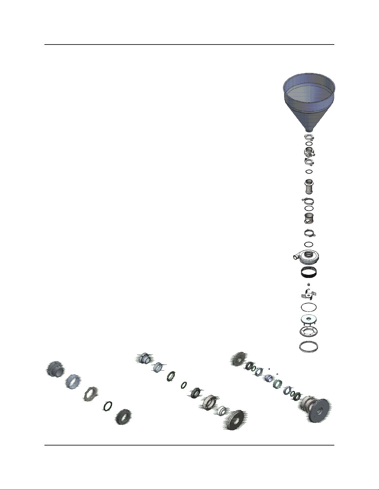
1. Carefully remove the back plate and inspect the back plate, the gasket, and the casing for
scratches, nicks, or wear.
2. For models with the DG seal, remove four screws from the back plate. Inspect the DG
seal insert, gland ring, and gaskets. Replace parts showing any wear or damage. Caution
should be used in handling the back plate. Avoid damage to the back plate surface
around the carbon seal opening.
3. Remove the carbon seal, cup, spring, and o-ring seal from the stub shaft.
4. Remove the drive collar from the shaft.
For E Seal replacement/reassembly, see page 13
5. Disconnect the inlet and outlet for the water to the stuffing.
6. Four screws hold the follower to the stuffing box. Remove all four screws.
7. Carefully slide the back plate assembly with the stuffing box off the shaft.
8. From the shaft, remove the inboard carbon seal, the cup, the seal spring, and the seal o-
ring.
9. Loosen the two set screws and remove the drive collar.
10. From the stub shaft, remove the carbon seal, cup, seal o-ring , and the follower.
Please note, special attention should be made to drive collar replacement, as incorrect
setting on the DG seal may allow for excessive wear on the seal
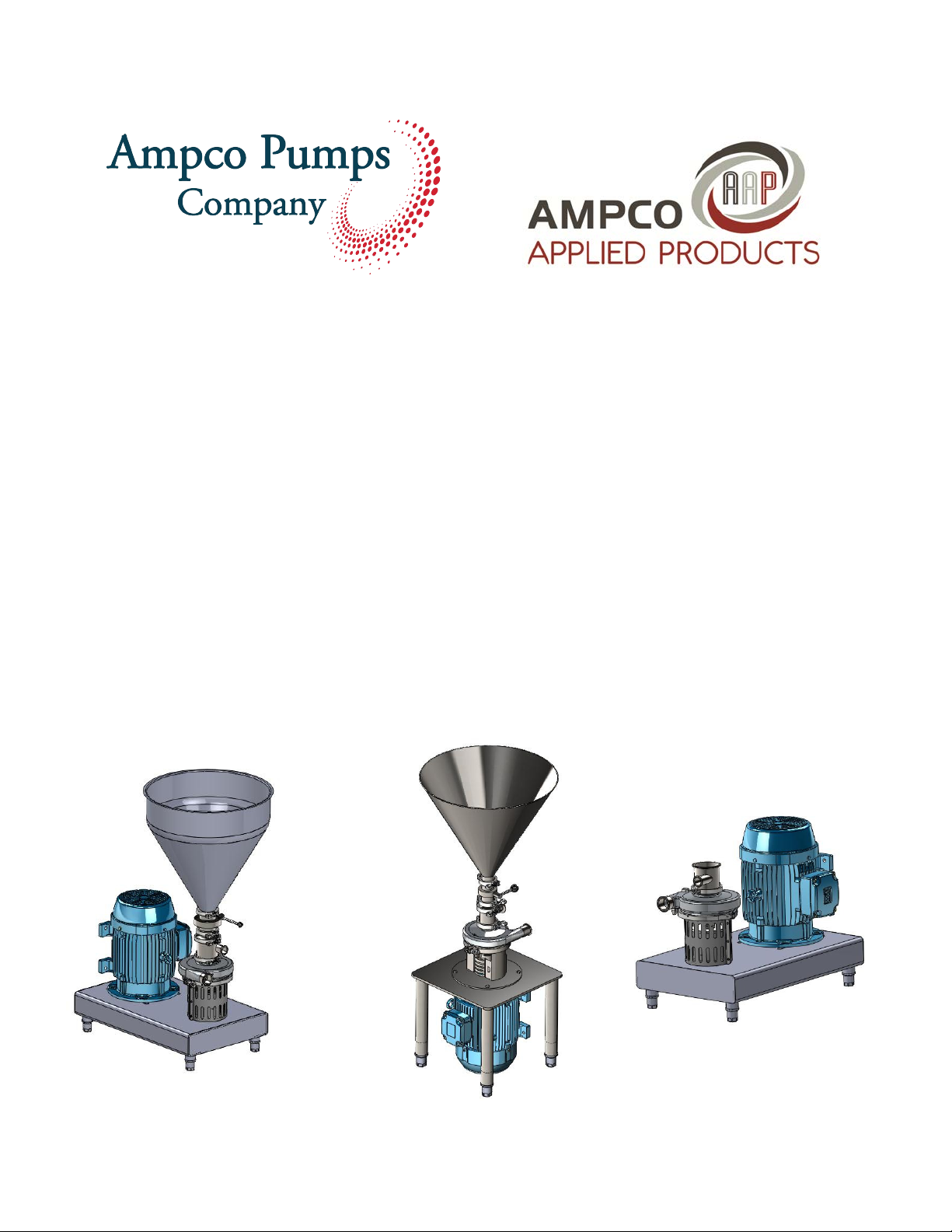
Models AC+2116 and AC+2116 System
1. To remove the drive motor from the AC+2116 or AC+2116
System, place a block suitable in size under the motor. Turn
the adjustable legs until the motor rests on the block.
2. Remove the seal guard.
3. Remove the carbon seal, cup, spring, and o-ring from the stub shaft.
4. Loosen the set screws and remove the drive collar.
5. The deflector should be removed by lifting it straight up and off.
6. Use the appropriate wrench to remove the four nuts, bolts, and
lock washers that secure the motor to the base.
7. The motor should now rest on the block. Lift the base from the
motor. The stub shaft should remain attached to the motor.
8. Loosen the socket head cap screw in the shaft collar and slide
the collar off.
9. Use a flat bar to pry beneath the stub shaft and remove it from the
motor shaft.
10. Check the stub shaft for nicks or scratches that may cause o-
ring seal wear and leaking.
11. To remove the adapter ring and spacers, set the base on its
side and hold the adapter ring while removing the six socket
head screws in the bottom of the base.
12. Remove the legs from the base.
13. Inspect all blender o-rings for damage and replace as needed.
Ampco Pumps Company AC+ Dry Blender Manual M-028 Rev C 12.20