3 PRODUCT OVERVIEW
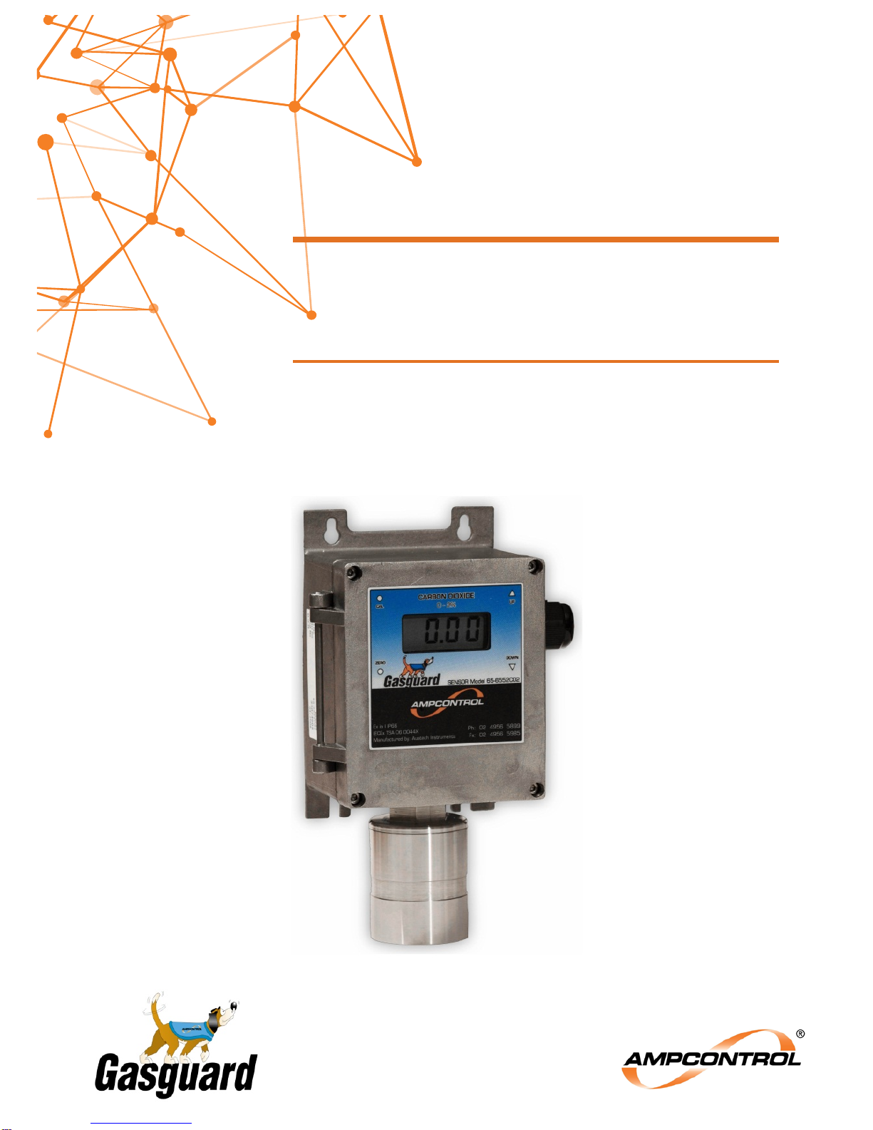
Ampcontrol’s Gasguard Infrared Carbon Dioxide Sensor / Transmitters are supplied complete with an
amplifier and a Liquid Crystal Display.
The Transmitter/Sensor assembly is an IEC Ex ia Group I certified assembly. The Certification is based
on the unit being sealed to IP 66 and the appropriate checks being made on the Intrinsically Safe
Parameters of the overall system the transmitter is connected into.
The Transmitter and Sensor can be mounted as an integral device but there is also an option to mount
the sensor separately up to 10m from the transmitter. In the remote configuration the sensor is factory
fitted with a type 2S cable which is potted directly into the sensor assembly.
The sensor is designed to provide a standardised output applicable for the gas range. This signal is not
for direct connection to other devices and so the amplifier PCB in the transmitter housing is used to
condition the signal, provide calibration functions and produce a 4-20mA signal.
The transmitter and amplifier assembly is configured in the factory for a specific gas range.
The Gasguard Infrared Carbon Dioxide Sensor / Transmitters operate on the Infrared Absorption
principal and provide a linear 4-20mA DC current output.
Unique part numbers in accordance with the following scheme identifies the sensor unit configurations:
Part Number 65-6552XXX series is for Infra-red sensor units.
Note: In the part numbers listed above, XXX represents the chemical symbol for the gas
detected by the unit. For example, 65-6552CO2-2 is the part number for an Infra-red
transmitter unit designed to detect Carbon Dioxide (CO2) in the range of 0 -2%.
Key Features:
•Economical Fixed Gas Sensor / Transmitter
•Rugged Construction
•Reliable
•Certified Intrinsically Safe – Ex ia
•LCD Display
•Non-Intrusive Closed Case Calibration
3.1 Sensor
3.1.1 Carbon Dioxide Gas Sensor
The Carbon Dioxide Gas Sensor works on the infra-red gas absorption principle. An infra-red light
source illuminates the sensor through a gas pathway with an optical filter that selects the appropriate
wavelength for the gas being detected; the presence of this gas reduces the amount of infra-red energy
reaching the detector. This difference in infra-red energy with and without gas is used to measure the
amount of gas present, and is converted to an electrical output of 4–20mA by the amplifier electronics.
3.1.2 Humidity
Sensors cannot operate in a condensing atmosphere. In such an environment, a thin film of water can
form across the membrane, effectively sealing it and stopping the passage of gas into the sensor. On
evaporation of this water the sensor usually resumes normal operation. Above 90% R.H. the sensor
accumulates water vapour and may form condensation to block the infra-red path used for gas
detection. Provided the exposure to these extremes of humidity has not been for a long period, the
sensors will recover when exposed to R.H. in the range 15% to 90%.