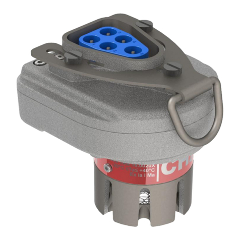
Ampcontrol Gasguard 2 User manual

Version: 1, July 2020
Designed and manufactured in Australia by Ampcontrol Pty Ltd
GG2 COMMUNICATIONS
4-20mA/IMAC/RS485
UserManual

Ampcontrol Pty Ltd –ABN 28 000 915 542
GG2 COMMUNICATIONS USER MANUAL
GG2B032
Version 1 –JULY/2020
Uncontrolled Copy - Refer to Ampcontrol Website for Latest Version
Page 2 of 22
APPROVED FOR EXTERNAL DISTRIBUTION –PROPERTY OF AMPCONTROL PTY LTD –NOT TO BE REPRODUCED IN PART
WARNING!
The warning symbol highlights a potential risk malfunction or loss of
performance
Please share these warnings with other operators.
CAUTION!
The caution symbol highlights a potential risk of damage to
equipment.
Please share these cautions with other operators.
NOTE
The note symbol highlights key information.
Please share these notes with other operators.
ENVIRO
The enviro (environmental) symbol highlights areas which may have an
impact on the surrounding fauna and/or flora.

Ampcontrol Pty Ltd –ABN 28 000 915 542
GG2 COMMUNICATIONS USER MANUAL
GG2B032
Version 1 –JULY/2020
Uncontrolled Copy - Refer to Ampcontrol Website for Latest Version
Page 3 of 22
APPROVED FOR EXTERNAL DISTRIBUTION –PROPERTY OF AMPCONTROL PTY LTD –NOT TO BE REPRODUCED IN PART
Copyright Notice
The Ampcontrol GG2 Display described in this document is the property of AMPCONTROL PTY LTD. It
is furnished under a license agreement and is to be used only in accordance with the terms of the
agreement.
No part of the hardware or documentation may be reproduced, transmitted, transcribed, stored in any
retrieval system, or translated into any language or computer language, in any form or by any means,
without prior written permission of AMPCONTROL PTY LTD.
Disclaimer
While every effort has been made to assure the accuracy and clarity of this document, AMPCONTROL
PTY LTD assumes no liability resulting from any omissions in this document, or from misuse of the
information obtained herein. The information in this document has been carefully checked and is believed
to be entirely reliable with all of the necessary information included. AMPCONTROL PTY LTD reserves
the right to make changes to any products described herein to improve reliability, function, or design, and
reserves the right to revise this document and make changes from time to time in content hereof with no
obligation to notify any persons of revisions or changes. AMPCONTROL PTY LTD does not assume any
liability arising out of the application or any use of any product or circuit described herein; neither does it
convey license under its patent rights or the rights of others.
Before You Begin
Thank you for purchasing from the Ampcontrol GG2 range.
WARNING!
In the interests of safety and correct equipment operation, please
take the time to read and understand the content in this manual.
Ampcontrol Contact Details
7 Billbrooke Close, Cameron Park, NSW, 2285
P +61 1300 267 373 | F +61 2 4903 4888
EMAIL: customerservice@ampcontrolgroup.com
WEB: ampcontrolgroup.com

Ampcontrol Pty Ltd –ABN 28 000 915 542
GG2 COMMUNICATIONS USER MANUAL
GG2B032
Version 1 –JULY/2020
Uncontrolled Copy - Refer to Ampcontrol Website for Latest Version
Page 4 of 22
APPROVED FOR EXTERNAL DISTRIBUTION –PROPERTY OF AMPCONTROL PTY LTD –NOT TO BE REPRODUCED IN PART
TABLE OF CONTENTS
DEFINITIONS ......................................................................................................5
1 SAFETY AND OTHER WARNINGS..................................................................6
1.1 Safe Use of Equipment..............................................................................6
1.2 Supplementary Documentation..................................................................6
2 RECEIVING AND STORAGE............................................................................7
2.1 Receiving...................................................................................................7
2.2 Inspection..................................................................................................7
2.3 Storage after Delivery................................................................................7
2.4 Unpacking of Equipment............................................................................7
3 GG2 COMMUNICATIONS ................................................................................8
3.1 Overview....................................................................................................8
3.2 GG2 Detector Types..................................................................................8
4 IMAC COMMUNICATIONS...............................................................................9
4.1 GG2 Detector Removal..............................................................................9
4.2 iMAC Registers..........................................................................................9
4.3 Gasguard Live Registers .........................................................................12
4.4 Hard Fault Output Values ........................................................................17
5 MODBUS COMMUNICATIONS ......................................................................18
5.1 GG2 Detector Removal............................................................................18
5.2 Register Map ...........................................................................................18

Ampcontrol Pty Ltd –ABN 28 000 915 542
GG2 COMMUNICATIONS USER MANUAL
GG2B032
Version 1 –JULY/2020
Uncontrolled Copy - Refer to Ampcontrol Website for Latest Version
Page 5 of 22
APPROVED FOR EXTERNAL DISTRIBUTION –PROPERTY OF AMPCONTROL PTY LTD –NOT TO BE REPRODUCED IN PART
DEFINITIONS
Term
Definition
CO2
Carbon Dioxide
CH4
Methane
CO
Carbon Monoxide
O2
Oxygen
H2S
Hydrogen Sulphide
NATA
National Association of Testing Authorities, Australia
NDIR
Non-Dispersive Infra-red
Warm Up Time
Time interval, with the equipment in a stated atmosphere, between the time
when the equipment is switched on and the time when the indication reaches
and remains within the stated tolerances
AS 4641:2007
Electrical apparatus for detection of oxygen and other gases and vapours at
toxic levels - general requirements and test methods
AS 2290.3-1990
Electrical equipment for coal mines - maintenance and overhaul Part 3:
maintenance of gas detecting and monitoring equipment.
AS/NZS 60079-
29.1:2008
Explosive atmospheres part 29.1: Gas detectors - Performance requirements of
detectors for flammable gases
IEC 60079.0:2011
Explosive atmospheres - Part 0: Equipment - General requirements
IEC 60079.11:2011
Explosive atmospheres - Part 11: Equipment protection by intrinsic safety "i"
GG2
Gasguard 2
ILAC
International Laboratory Accreditation Cooperation Mutual Recognition
Arrangement.
ILAC is the international organisation for accreditation bodies operating in
accordance with ISO/IEC 17011 and involved in the accreditation of conformity
assessment bodies including calibration laboratories (using ISO/IEC 17025),
testing laboratories (using ISO/IEC 17025), medical testing laboratories (using
ISO 15189), inspection bodies (using ISO/IEC 17020) and proficiency testing
providers using ISO/IEC 17043.

Ampcontrol Pty Ltd –ABN 28 000 915 542
GG2 COMMUNICATIONS USER MANUAL
GG2B032
Version 1 –JULY/2020
Uncontrolled Copy - Refer to Ampcontrol Website for Latest Version
Page 6 of 22
APPROVED FOR EXTERNAL DISTRIBUTION –PROPERTY OF AMPCONTROL PTY LTD –NOT TO BE REPRODUCED IN PART
1 SAFETY AND OTHER WARNINGS
For safety reasons, the GG2 Display must be installed, operated and serviced only by competent
personnel. Please read and understand this instruction manual completely before installing, operating or
servicing this equipment. Failure to install or operate this instrument in accordance with the instructions
contained in this manual may create hazardous operating conditions.
1.1 Safe Use of Equipment
The equipment supplied has been designed and manufactured to ensure safe operation. The equipment
must only be used within the design parameters.
The instructions within this manual must be observed as an aid towards achieving the safest possible
installation.
Persons responsible for installation, maintenance, or operation, must observe the following
instructions:
Changes to Equipment
Changes in the design and modifications to the equipment are not permitted. Unauthorised changes
made to the hardware or operating firmware will void the manufacturer's warranty, and may
compromise the integrity of the system into which it is installed and other connected equipment.
Equipment Knowledge
Experience with, or understanding of, this equipment is essential for the safe installation and removal of
the equipment. Therefore, please read and understand this manual prior to use. Competency based
training courses are recommended and are available on request.
Manual Handling
Precautions have been taken to ensure all equipment is safe to handle and free from sharp edges.
However, care should always be taken when handling enclosures and gloves should be worn.
Installation
Correct operation and safety depend on GG2 Display and associated equipment being installed
correctly. Mechanical and or electrical installation and maintenance of plant and equipment must only
be carried out by appropriately qualified personnel and must be tested thoroughly prior to operation.
Operation
As safety depends on GG2 Display functioning correctly it is highly recommended that all safety
functions of the unit be periodically tested to ensure correct operation.
1.2 Supplementary Documentation
The GG2 Display User Manual is expected to be read in conjunction with the following documentation:
GG2B011 GG2 Detector User Manual
GG2B023 GG2 Display User Manual
GG2B033 GG2 Design, Installation and Maintenance Application Guide

Ampcontrol Pty Ltd –ABN 28 000 915 542
GG2 COMMUNICATIONS USER MANUAL
GG2B032
Version 1 –JULY/2020
Uncontrolled Copy - Refer to Ampcontrol Website for Latest Version
Page 7 of 22
APPROVED FOR EXTERNAL DISTRIBUTION –PROPERTY OF AMPCONTROL PTY LTD –NOT TO BE REPRODUCED IN PART
2 RECEIVING AND STORAGE
2.1 Receiving
All possible precautions are taken to protect the equipment against damage or losses during shipment;
however, before accepting delivery, check all items against the packing list or bill of loading. If there is
evidence of physical damage, notify Ampcontrol immediately.
Notify Ampcontrol immediately in the case of any discrepancies to the packing list. Keep a record of any
claims and correspondence. Photographs are recommended.
Where practicable do not remove protective covers prior to installation unless there are indications of
damage. Boxes opened for inspection and inventory should be carefully repacked to ensure protection of
the contents or else the parts should be packaged and stored in a safe place. Examine all packing
boxes, wrappings and covers for items attached to them, retain and store any approval documentation
for your safety file as applicable prior to wrapping being discarded.
2.2 Inspection
Equipment that is found to be damaged or has been modified away from its published specifications
must not be used. Please contact Ampcontrol if the equipment is suspected to be different than that
ordered or if it does not match the published specifications.
2.3 Storage after Delivery
When the equipment is not to be installed immediately, proper storage is important to ensure protection
of equipment and validity of warranty.
All equipment should be stored indoors between 0-40˚C, preferably on shelves and protected from
moisture and sunlight.
2.4 Unpacking of Equipment
The method of packing used will depend on the size and quantity of the equipment. The following
cautions should be interpreted as appropriate.
CAUTION!
Take care when unpacking crates as the
contents may have shifted during transport.
ENVIRO
The disposal of packaging materials, replaced parts, or components
must comply with environmental restrictions without polluting the soil,
air or water.
Ensure that any timber and cardboard used as packaging is disposed
of in a safe and environmentally responsible manner.
Where possible, dispose of all waste products i.e. oils, metals, plastic
and rubber products by using an approved recycling service centre.

Ampcontrol Pty Ltd –ABN 28 000 915 542
GG2 COMMUNICATIONS USER MANUAL
GG2B032
Version 1 –JULY/2020
Uncontrolled Copy - Refer to Ampcontrol Website for Latest Version
Page 8 of 22
APPROVED FOR EXTERNAL DISTRIBUTION –PROPERTY OF AMPCONTROL PTY LTD –NOT TO BE REPRODUCED IN PART
3 GG2 COMMUNICATIONS
3.1 Overview
The GG2 Display Module is an intrinsically safe apparatus for the purpose of displaying and transmitting
sensor data and system information. The GG2 Display consists of a certified GG2 Display Module and
associated wiring installed within an IP66 rated stainless steel enclosure.
The GG2 Display is available in three variants, a glanded display supporting iMAC/RS485
communication and two pluggable versions supporting 4-20mA+iMAC and 4-20mA+RS485
communication.
This document details the Modus and iMAC communication protocols. Refer to the following sections
Modbus Communication –Section 5.
iMAC Communication –Section 4.
3.2 GG2 Detector Types
The following table outlines some of the common part numbers. For more information on the GG2 range
of products, refer to GG2B026 GG2 Monitoring Solution Technical Datasheet.
Table 1: GG2 Detector Type Table
Gas
Type
Detector
Technology
Measurement Range
Ampcontrol Part
Numbers
CH4
Catalytic
0-5% v/v
177871
CH4
IR
0-5% v/v
177870
CH4
IR
0-100% v/v
190998
CO2
IR
0-2% v/v
180734
CO2
IR
0-5% v/v
180733
CO
Electrochemical
0-50ppm
177873
CO
Electrochemical
0-100ppm
177874
O2
Electrochemical
0-25% v/v
177872
H2S
Electrochemical
0-50ppm
178228
H2S
Electrochemical
0-100ppm
193071
Figure 1: GG2 Example System (iMAC Communication)
iMAC Fieldbus

Ampcontrol Pty Ltd –ABN 28 000 915 542
GG2 COMMUNICATIONS USER MANUAL
GG2B032
Version 1 –JULY/2020
Uncontrolled Copy - Refer to Ampcontrol Website for Latest Version
Page 9 of 22
APPROVED FOR EXTERNAL DISTRIBUTION –PROPERTY OF AMPCONTROL PTY LTD –NOT TO BE REPRODUCED IN PART
4 IMAC COMMUNICATIONS
4.1 GG2 Detector Removal
If iMAC is activated and the detector is removed, all bit fields will go to all zeros and all numerical values
will go to 0xFFFF. The setpoint flag bits and data invalid bit will go high (1) and are exceptions to the
previous rule.
4.2 iMAC Registers
Flags Data Register
SCADA* - These registers/bits must be monitored and included in the trip permissives for all safety
system applications when this protocol is selected.
Bit
Description
Value
iMAC
Exception
Trigger?
R/W
Application Notes
SCADA*
0
Analogue
input moved
away from
healthy
region and
reached
Setpoint 1
1 = Warn
Yes
R
This bit is set when it
traverses the setpoint.
1
Analogue
input moved
away from
healthy
region and
reached
Setpoint 2
1 = Warn
Yes
R
This bit is set when it
traverses the setpoint.
2
Analogue
input moved
away from
healthy
region and
reached
Setpoint 3
1 = Trip
Yes
R
This bit is set when it
traverses the setpoint
i.e. typical used for Tripping
in RTGMS / Gas monitoring
SLP codes.
3
SP1 flag not
set AND
SP2 flag not
set
1 = Warn
Yes
R
Used for AIM compatibility.
4
SP2 flag set
AND SP3
flag not set
1 = Warn
Yes
R
Used for AIM compatibility.
5
Power
supply <
Setpoint A
(warn)
1 = Warn
Yes
R
This bit is set when it
traverses the setpoint.
6
Power
supply <
Setpoint B
(trip)
1 = Trip
Yes
R
This bit is set when it
traverses the setpoint
i.e. typical used for Tripping
in RTGMS / Gas monitoring
SLP codes.

Ampcontrol Pty Ltd –ABN 28 000 915 542
GG2 COMMUNICATIONS USER MANUAL
GG2B032
Version 1 –JULY/2020
Uncontrolled Copy - Refer to Ampcontrol Website for Latest Version
Page 10 of 22
APPROVED FOR EXTERNAL DISTRIBUTION –PROPERTY OF AMPCONTROL PTY LTD –NOT TO BE REPRODUCED IN PART
Bit
Description
Value
iMAC
Exception
Trigger?
R/W
Application Notes
SCADA*
7
System fault
1 = System
has detected
a hardware,
Detector or
software fault.
0 = No fault in
operation
detected.
Yes
R
System fault
E.g. sensor head missing /
display <-> head comms
fault, etc.
8
Cal cup on
1 = Cup on
Yes
R
The GG2 senses the
magnets in our approved cup
(E.g. bump test, zero / span
adjust, calibration)
9
Gas Value
Invalid
1 = Analogue
4-20mA gas
reading is not
reflecting the
real world gas
value.
Yes
R
Analogue 4-20mA gas
reading is not reflecting the
real world gas value. (I.e. it is
currently in fault or warmup
or otherwise unreliable. This
includes the sensor being in
warmup, even if 4-20mA is
returning the sensor value
during warmup).
10
Detector
Head
Warmup
1 = Warmup
busy
No
R
GG2 Detector currently in
warmup mode
11
Linearity
test due
1 = Linearity
test due
No
R
International Laboratory
Accreditation Cooperation
Mutual Recognition
Arrangement. Linearity (i.e.
NATA) test is now overdue.
12
Overrange
latch on
CH4
catalytic
detector
OR
NDIR
incomplete
adjustment
1 =
Overrange
latch on CH4
Catalytic
detector
OR
IR adjustment
incomplete
Yes
R
Overrange latch on CH4
catalytic detector
CH4 has exceeded full scale.
The sensor is switched off to
protect it from damage.
OR
NDIR incomplete adjustment
Non dispersive Infra Red
sensors had an incomplete
calibration sequence. This is
unique to this sensor type. In
short, once you start
zero/span adjustment, the
values are wiped at the start.
13
Hardware
fault
1 = Hardware
fault
Yes
R
A fault which
impedes/prevents gas
detection/other critical
function has been detected.

Ampcontrol Pty Ltd –ABN 28 000 915 542
GG2 COMMUNICATIONS USER MANUAL
GG2B032
Version 1 –JULY/2020
Uncontrolled Copy - Refer to Ampcontrol Website for Latest Version
Page 11 of 22
APPROVED FOR EXTERNAL DISTRIBUTION –PROPERTY OF AMPCONTROL PTY LTD –NOT TO BE REPRODUCED IN PART
Bit
Description
Value
iMAC
Exception
Trigger?
R/W
Application Notes
SCADA*
14
Telemetry
test active
1 = Telemetry
test active
Yes
R
The GG2 Display output
value is forced via the GG2
UI or the RTGMS (iMAC
master)
Refer to Command
parameter block 0, parm 2
15
Bypass ON
1 = Bypass
detected
Yes
R
The Gasguard RTGMS uses
a DI4 for bypassing an
individual boundary (tripping)
detector, This bit is set when
the GG2 is addressed to the
corresponding bypass i.e.
the DI4 module being
monitored by the GG2.
Refer to Command
parameter block 0, parm3
Analogue Input
SCADA* - These registers/bits must be monitored and included in the trip permissives for all safety
system applications when this protocol is selected.
Bit
Description
Value
iMAC
Exception
Trigger?
R/W
Application Notes
SCADA*
15 - 0
4 - 20 mA
4-20mA
representation
of the Gas
Reading.
Yes
(See
parameters)
R
Value can be forced via the
Telemetry Test if system not
in Fault. Sensor Reading
shown during warmup.
Hard
fault
values
Power Supply Input
SCADA* - These registers/bits must be monitored and included in the trip permissives for all safety
system applications when this protocol is selected.
Bit
Description
Value
iMAC
Exception
Trigger?
R/W
Application
Notes
SCADA*
15 - 8
0 - 24 VDC (MSB
for AIM mode)
AIM Mode : 0 - 2400
(0.00 - 24.00 V)
GG2 Mode : 0 - 240
(0.0 - 24.0 V)
No
R
7 - 0
0 - 24 VDC (LSB
for AIM mode)
0 - 24 VDC (GG2
mode)

Ampcontrol Pty Ltd –ABN 28 000 915 542
GG2 COMMUNICATIONS USER MANUAL
GG2B032
Version 1 –JULY/2020
Uncontrolled Copy - Refer to Ampcontrol Website for Latest Version
Page 12 of 22
APPROVED FOR EXTERNAL DISTRIBUTION –PROPERTY OF AMPCONTROL PTY LTD –NOT TO BE REPRODUCED IN PART
4.3 Gasguard Live Registers
The following features are available via Ampcontrol’s Digital Solution.
Block 0
Linked to the Flags Register.
Block 1
Linked to the Analogue Input Register.
Block 0
Description
Value
R/W
Application Notes
0,0
iMAC Address - Flags
register
0 - 255
W
iMAC Address
0,1
Exception Trigger
100 - 20,000
W
Step change between the 1s
samples to trigger exception.
Forces the iMAC Controller to
temporarily prioritise this
module, as opposed to a round
robin scan which could have
as much as a 30s delay at 300
baud
0,2
Detector gas reading
permyriad - unaffected by
telemetry test
-32768 to 32768
Permyriad
W
Not overridden by Telemetry
testing (is still however subject
to fault and warmup values)
0,3
Future use
Bit 15 - 7 (255 to 128)
W
AIM Compatibility mode
Bit 8 : Yes = 1 (Power
supply register is 16bit)
Bypass address
Bit 7 - 0 : 1 to 255
(where 0 is disabled)
iMAC data bus address to
monitor for displaying bypass
message
Relevant bits on the data bus:
Data bit 8 = "Remote bypass"
(via PLC or similar)
Data bit 0 = "Local bypass"
(aligns with a DI4 input
module)
Block 1
Description
Value
R/W
Application Notes
1,0
iMAC Address -
Analogue register
0 - 255
W
iMAC address
1,1
Setpoint 1 (Gas)
4000 - 20000
W
RTGMS used for calibration,
fault i.e. loss of analogue loop
or negative drift alarm
1,2
Setpoint 2 (Gas)
4000 - 20000
W
RTGMS used for Warn

Ampcontrol Pty Ltd –ABN 28 000 915 542
GG2 COMMUNICATIONS USER MANUAL
GG2B032
Version 1 –JULY/2020
Uncontrolled Copy - Refer to Ampcontrol Website for Latest Version
Page 13 of 22
APPROVED FOR EXTERNAL DISTRIBUTION –PROPERTY OF AMPCONTROL PTY LTD –NOT TO BE REPRODUCED IN PART
Block 2
Linked to the Power Supply Register.
1,3
Setpoint 3 (Gas)
4000 - 20000
W
RTGMS used for Trip
Block 2
Description
Value
R/W
Application Notes
2,0
iMAC Address - Power
supply register
0 - 255
W
iMAC address
2,1
Power Supply Setpoint A
- (AIM Mode)
OR
SPARE for GG2 Mode
AIM Mode : 1000 - 2400
(10.00 to 24.00) Warn
W
RTGMS used for Warn
GG2 Mode : n/a
2,2
Power Supply Setpoint B
- (AIM Mode) MSB
OR
Power Supply Setpoint A
- Warn / Alarm (GG2
Mode)
GG2 Mode
: 100 - 240
(10.0 -
24.0 V)
Warn
AIM Mode
800 - 2400
(8.00 to
24.00)
Trip
W
AIM Mode RTGMS used for
Trip
GG2 Mode used for Warn
Power Supply Setpoint B
- Trip (AIM Mode) LSB
OR
Power Supply Setpoint B
- Trip (GG2 Mode)
GG2 Mode
: 80 - 240
(10.0 -
24.0 V)
Trip
AIM Mode RTGMS used for
Trip
GG2 Mode used for Trip
2,3
Hysteresis config
Bit 15 - 12
W
Hysteresis setting 0 - 7.5% in
0.5% steps
(1 = 0.5%, 2 = 1% etc.)
Healthy config
Bit 11 - 9
000': always healthy,
'001': healthy < SP1,
'010': SP1 ≤ healthy < SP2,
'011': SP2 ≤ healthy < SP3,
'100': healthy ≥ SP3
Warmup and fault output
behaviour
Bit 8
‘1’ for high warmup and
soft-fault high,
‘0’ for low warmup and
soft-fault low on 4-20mA
bus
Nominal Values
Low Fault - 2.8mA 2800
Low warmup - 3mA 3000
Under range - 3.2mA 3200
NDIR (only) zero shift negative
- 3.7mA 3700
Normal range - ~4-20mA
4000-20000
Over range - 20.8mA 20800
High warmup - 21mA 21000
High fault - 21.2mA 21200
iMAC address for 32-bit
sys clock
Bit 7 - 0
1 - 254
(excluding the last
address of each data
block, which would
The iMAC controller will
publish a 32 bit clock on the
data bus at this address (and
+1), so that the GG2 can use it

Ampcontrol Pty Ltd –ABN 28 000 915 542
GG2 COMMUNICATIONS USER MANUAL
GG2B032
Version 1 –JULY/2020
Uncontrolled Copy - Refer to Ampcontrol Website for Latest Version
Page 14 of 22
APPROVED FOR EXTERNAL DISTRIBUTION –PROPERTY OF AMPCONTROL PTY LTD –NOT TO BE REPRODUCED IN PART
Block 3
Only available via a Read/Write S/N. Not visible via regular rollcall page on the Controller.
result in the RTC value
being split across two
data scan packets. Thus
address 3,7,11 etc. are
not allowed)
Address of MS word of
RTC (assumes LS word
is address + 1)
for a clock sync
Block 3
Description
Value
R/W
Application Notes
3,0
Detector Temperature
Degrees C * 100
(signed)
-327.68deg C to
327.68deg C
R
3,1
Detector Pressure
-32768 to 32768
Hectopascals (hPa)
(Unprocessed from the
LUA parameter module
"Pressure")
R
3,2
Detector Humidity
% * 100 (signed)
-xx.xx% to xx.xx%
(Using the parameter
manager subscription
"Humidity")
R
3,3
Command registers
MSB
Command code:
'0x00' : Idle
'0x1E' : Perform a
Catalytic latch reset
'0x2D' : Perform a
Remote telemetry test
W
To trigger a command, the
master device will write a
command code and command
data into this register, with the
busy bit set.
On completion of the task, the
Gasguard 2 module will modify
the result data to reflect the
outcome, clearing the busy bit
(The command code must not
be modified in this step)
LSB
Command data (from
master):
Bit 7 : 1 = Busy
Bit 6 - 0 : Future use
(command parameters)
OR
Result data (from
module):
Bit 7 : 0 = Complete
without error
Bit 6 - 0 : Future use
(command error codes)

Ampcontrol Pty Ltd –ABN 28 000 915 542
GG2 COMMUNICATIONS USER MANUAL
GG2B032
Version 1 –JULY/2020
Uncontrolled Copy - Refer to Ampcontrol Website for Latest Version
Page 15 of 22
APPROVED FOR EXTERNAL DISTRIBUTION –PROPERTY OF AMPCONTROL PTY LTD –NOT TO BE REPRODUCED IN PART
Block 4
Only available via a Read/Write S/N. Not visible via regular rollcall page on the Controller.
Block 5
Only available via a Read/Write S/N. Not visible via regular rollcall page on the Controller.
Block 4
Description
Value
R/W
Application Notes
4,0
Last time response test
result (t90)
0 to 65535; 0.0 to
6553.5s
R
4,1
Hours since last linearity
test
0 to 65535 hours
R
4,2
Time in seconds of last
Cal cup application
0 to 65535 seconds
R
4,3
Power supply data
register
MSB
0 - 240 (0.0 - 24.0 V)
(Regardless of AIM /
GG2 mode)
-
Internal usage
Do not modify or use
R
Do not modify or use
Block 5
Description
Value
R/W
Application Notes
5,0
Future use
Bit 15 - 3 : Future use
W
Time Stamp post-box
selection
(at Parm 5,2 + 5,3)
Bit 2 - 0 :
'000' : Calibration
(linearity) test
timestamp
'001' : Telemetry test
start timestamp
'010' : t90 test
timestamp
'011' : RTC time
(current)
5,1
Detector type (incl gas
range and units)
Bit 15 - 8 : See detector
types spreadsheet
(8 bit reserved for this,
to avoid limiting the
future)
R
Future use
Bit 7 - 5 : Future use
28 days since Cal cup
applied (for > 20s)
Bit 4: 1 = Yes
14 days until Linearity
test due
Bit 3:
1 = Yes
The 6 monthly
calibration check is due.

Ampcontrol Pty Ltd –ABN 28 000 915 542
GG2 COMMUNICATIONS USER MANUAL
GG2B032
Version 1 –JULY/2020
Uncontrolled Copy - Refer to Ampcontrol Website for Latest Version
Page 16 of 22
APPROVED FOR EXTERNAL DISTRIBUTION –PROPERTY OF AMPCONTROL PTY LTD –NOT TO BE REPRODUCED IN PART
Block 6
Only available via a Read/Write S/N. Not visible via regular rollcall page on the Controller.
Must be performed by
NATA certified 3rd
parties. E.g. CMTS, Cal
Pacific etc.
Last Linearity test,
number of test points
Bits 2 - 0 : 0 to 6 points
5,2
Post-box options :
0 : Linearity test
timestamp high-word
1 : Telemetry test start
timestamp high-word
2 : t90 test timestamp
high-word
3 : RTC current high-
word
Unix style timestamp,
using the Ampcontrol
epoch -
01-01-2000 00:00.
Big endian
Note, it will take the
GG2 at least 1.5 second
to change the post-box
value before it can be
read out. (this after the
write s/n is complete)
R
5,3
Post-box options :
0 : Linearity test
timestamp low-word
1 : Telemetry test start
timestamp low-word
2 : t90 test timestamp
low-word
3 : RTC current low-word
Block 6
Description
Value
R/W
Application Notes
6,0
Future use
Future use
W
6,1
Detector Serial number
high word
Detector SyteLine serial
number (10 digit)
32 bits (for calibration
tracking)
R
6,2
Detector Serial number
low word
6,3
Future use
MSB : Future use
R
Detector Software
Version
LSB : 8 bit version
number (unsigned)

Ampcontrol Pty Ltd –ABN 28 000 915 542
GG2 COMMUNICATIONS USER MANUAL
GG2B032
Version 1 –JULY/2020
Uncontrolled Copy - Refer to Ampcontrol Website for Latest Version
Page 17 of 22
APPROVED FOR EXTERNAL DISTRIBUTION –PROPERTY OF AMPCONTROL PTY LTD –NOT TO BE REPRODUCED IN PART
Block 7
Only available via a Read/Write S/N. Not visible via regular rollcall page on the Controller.
4.4 Hard Fault Output Values
Hard fault Output value
State
Nominal
Range
Units
Modbus
iMAC
HARD FAULT
N/A
x <= 2
N/A
N/A
N/A
LOW SOFT FAULT
2.8
2.6 < x <= 2.9
mA
-750
2800
LOW WARMUP
3
2.9 < x <=3.2
mA
-625
3000
UNDER RANGE
3.2
3.2 < x <4
mA
-500
3200
UNDER RANGE NDIR ONLY
3.7
3.7
mA
-187.5
3700
NORMAL RANGE
~4-20
4 <= x <= 20
mA
~
N/A
OVER RANGE
20.8
20 < x <= 20.8
mA
10500
20800
HIGH WARMUP
21
20.8 < x <= 21.1
mA
10625
21000
HIGH SOFT FAULT
21.2
21.1 < x <=21.4
mA
10750
21200
HARD FAULT
N/A
21.4 < x
N/A
N/A
N/A
Block 7
Description
Value
R/W
Application Notes
7,0
Display Serial number
high word
Display SyteLine serial
number (10 digit)
32 bits (for calibration
tracking)
R
7,1
Display Serial number
low word
7,2
Future use
MSB : Future use
R
Display Base Software
Version
LSB : 8 bit version
number (unsigned)
7,3
Future use
MSB : Future use
R
Display Application
Software (LUA) Version
LSB : 8 bit version
number (unsigned)

Ampcontrol Pty Ltd –ABN 28 000 915 542
GG2 COMMUNICATIONS USER MANUAL
GG2B032
Version 1 –JULY/2020
Uncontrolled Copy - Refer to Ampcontrol Website for Latest Version
Page 18 of 22
APPROVED FOR EXTERNAL DISTRIBUTION –PROPERTY OF AMPCONTROL PTY LTD –NOT TO BE REPRODUCED IN PART
5 MODBUS COMMUNICATIONS
5.1 GG2 Detector Removal
If Modbus is activated and the detector is removed, all bit fields will go to all zeros and all numerical
values will go to 0xFFFF. The setpoint flag bits will go high (1) and are exceptions to the previous rule.
5.2 Register Map
All values can be assumed to be the Modbus default endianness, big-endian. Any exceptions to this will
be noted in the Format column.
Safety Registers
SCADA* - These registers/bits must be monitored and included in the trip permissives for all safety
system applications when this protocol is selected.
Register
Description
R/W
Detail
Format
SCADA*
1
Detector gas reading
permyriad - unaffected by
telemetry test
R
Permyriad of full scale,
see Error! Reference s
ource not found.Error!
Reference source not
found.
Signed Int
2
Bit-inverted Detector gas
reading permyriad -
unaffected by telemetry test
R
Permyriad of full scale,
See Error! Reference s
ource not found.Error!
Reference source not
found.
Signed Int, bit
inversion
3
Heartbeat
R
Increments on each
cycle, nominally every
100ms.
Unsigned Int
4 –bit 0
Safety Word –system fault
R
system fault
bit
4 –bit 1
Safety gas value invalid i.e.
reg 1
R
Safety gas value invalid
bit
Operational Registers
SCADA* - These registers/bits must be monitored and included in the trip permissives for all safety
system applications when this protocol is selected.
Register
Description
R/W
Detail
Format
SCADA*
5
Detector gas reading
permyriad - may be forced
by telemetry test.
R
Permyriad of full scale,
see Error! Reference s
ource not found.Error!
Reference source not
found.
Signed Int
6 –bit 0
SP1 flag
R
1 = flag set
bit
6 –bit 1
SP2 flag
R
1 = flag set
bit
6 –bit 2
SP3 flag
R
1 = flag set
bit
6 –bit 3
Cal cup on
R
1 = cup on
bit
6 –bit 4
Calibration due (every 6
months)
R
1 = calibration due
bit
6 –bit 5
T90 test due (every 31
days)
R
1 = T90 test due
bit
6 –bit 6
Detector present
R
1 = detector present
bit
6 –bit 7
4-20mA loop activation
R
1 = 4-20mA loop active
bit

Ampcontrol Pty Ltd –ABN 28 000 915 542
GG2 COMMUNICATIONS USER MANUAL
GG2B032
Version 1 –JULY/2020
Uncontrolled Copy - Refer to Ampcontrol Website for Latest Version
Page 19 of 22
APPROVED FOR EXTERNAL DISTRIBUTION –PROPERTY OF AMPCONTROL PTY LTD –NOT TO BE REPRODUCED IN PART
Register
Description
R/W
Detail
Format
SCADA*
6 –bit 8
4-20mA loop fault
R
1 = 4-20mA loop fault
bit
i6 –bit 9
Latched catalytic detector
R
1 = detector latched
bit
6 –bit 10
Hardware fault
R
1 = fault
bit
6 –bit 11
Detector warmup
R
1 = in warmup
bit
6 –bit 12
Data valid
R
1 = data valid
bit
6 –bit 13
Sensor aged. Sensor
performance has
deteriorated due to age.
R
1 = sensor aged
bit
6 –bit 14
Out of operational temp
range.
R
1 = temp out of range
bit
6 –bit 15
Telemetry test active
R
1 = telemetry test in
progress
bit
7
RESERVED
8 –bit 0
System bypass
R/W
Write 1 to put device into
bypass. Write 0 to leave
bypass.
bit
8 –bit 1
Reset latched catalytic
R/W
Write 1 to activate the
reset, the value should
clear to 0.
bit
9 –bits 0-
7
FACTORY USE ONLY
9 –bit 8
Atmospheric pressure
fluctuation too great to
obtain stable reading
R
1 = true
bit
9 –bit 9
Sensor reading has gone
above 100%
R
1 = above range
bit
9 –bit 10
Sensor reading has gone
below -10%. Auto clears
when reading goes above
0%
R
1 = under range
bit
9 –bit 11
FACTORY USE ONLY
9 –bit 12
Unexpected calibration
values
R
1 = calibration values
are not correct
bit
9 –bits
13-15
RESERVED
10 –bits
0-11
FACTORY USE ONLY
10 –bit 12
Detector warming up
1 = in warmup
bit
10 –bit 13
Catalytic latch
1 = detector latched
bit
10 –bit 14
Incomplete adjustment
(NDIR)
1 = adjustment
incomplete
bit
10 –bit 15
FACTORY USE ONLY
11
Detector pressure
Hectopascals (hPa)
Signed Int
12
Detector temperature
Degrees Celsius(°C) *
100
Signed Int
13
Detector humidity
Permyriad
Signed Int
14
Detector bus voltage
Millivolts
Signed Int

Ampcontrol Pty Ltd –ABN 28 000 915 542
GG2 COMMUNICATIONS USER MANUAL
GG2B032
Version 1 –JULY/2020
Uncontrolled Copy - Refer to Ampcontrol Website for Latest Version
Page 20 of 22
APPROVED FOR EXTERNAL DISTRIBUTION –PROPERTY OF AMPCONTROL PTY LTD –NOT TO BE REPRODUCED IN PART
ID Info
SCADA* - These registers/bits must be monitored and included in the trip permissives for all safety
system applications when this protocol is selected.
Register
Description
R/W
Detail
Format
SCADA*
15
Maximum engineering unit
value
R
Real world gas value –
span
Signed Int
16
Minimum engineering unit
value
R
Real world gas value –
zero
Signed Int
17
Engineering unit number of
decimal places
R
Unsigned Int
18
Detector type
R
Please see 3.2 for
details
Unsigned Int
19
Detector Serial Number - Hi
Word
R
32bit
Unsigned Int
20
Detector Serial Number Lo
Word
R
21
Display Serial Number Hi
Word
R
32bit
Unsigned Int
22
Display Serial Number Lo
Word
R
23
Display Application
Software Version
R
Unsigned Int
24
Display Firmware Version
R
Unsigned Int
25
Detector Firmware Version
R
Unsigned Int
Setup
SCADA* - These registers/bits must be monitored and included in the trip permissives for all safety
system applications when this protocol is selected.
Register
Description
R/W
Detail
Format
SCADA*
26
Setpoint 1 permyriad (see
Error! Reference source n
ot found.).
R/W
Must be <SP2
Signed Int
27
Setpoint 2 permyriad (see
Error! Reference source n
ot found.).
R/W
Must be >SP1 and <SP3
Signed Int
28
Setpoint 3 permyriad (see
Error! Reference source n
ot found.).
R/W
Must be >SP2
Signed Int
29
Normal operation range.
R/W
0: never activate
setpoint
1: healthy < SP1
2: SP1 ≤ healthy < SP2
3: SP2 ≤ healthy < SP3
4: healthy ≥ SP3
Unsigned Int
30
RTC date and time
R
Time in seconds since
01-01-2000 00:00
All zeros if time lost or
faulty
32 bit
Unsigned Int
31
RTC date and time
R
This manual suits for next models
1
Table of contents
Other Ampcontrol Measuring Instrument manuals
Popular Measuring Instrument manuals by other brands

Spirometrics
Spirometrics FLOWMATE V PLUS user manual

Rosemount
Rosemount 8800D Series Reference manual

Hanna Instruments
Hanna Instruments HI 9126 instruction manual

Steren
Steren COM-562 user manual

Horiba Scientific
Horiba Scientific LAQUA WQ-300 Series quick guide

AMAZON COMMERCIAL
AMAZON COMMERCIAL B07VZ735PN manual