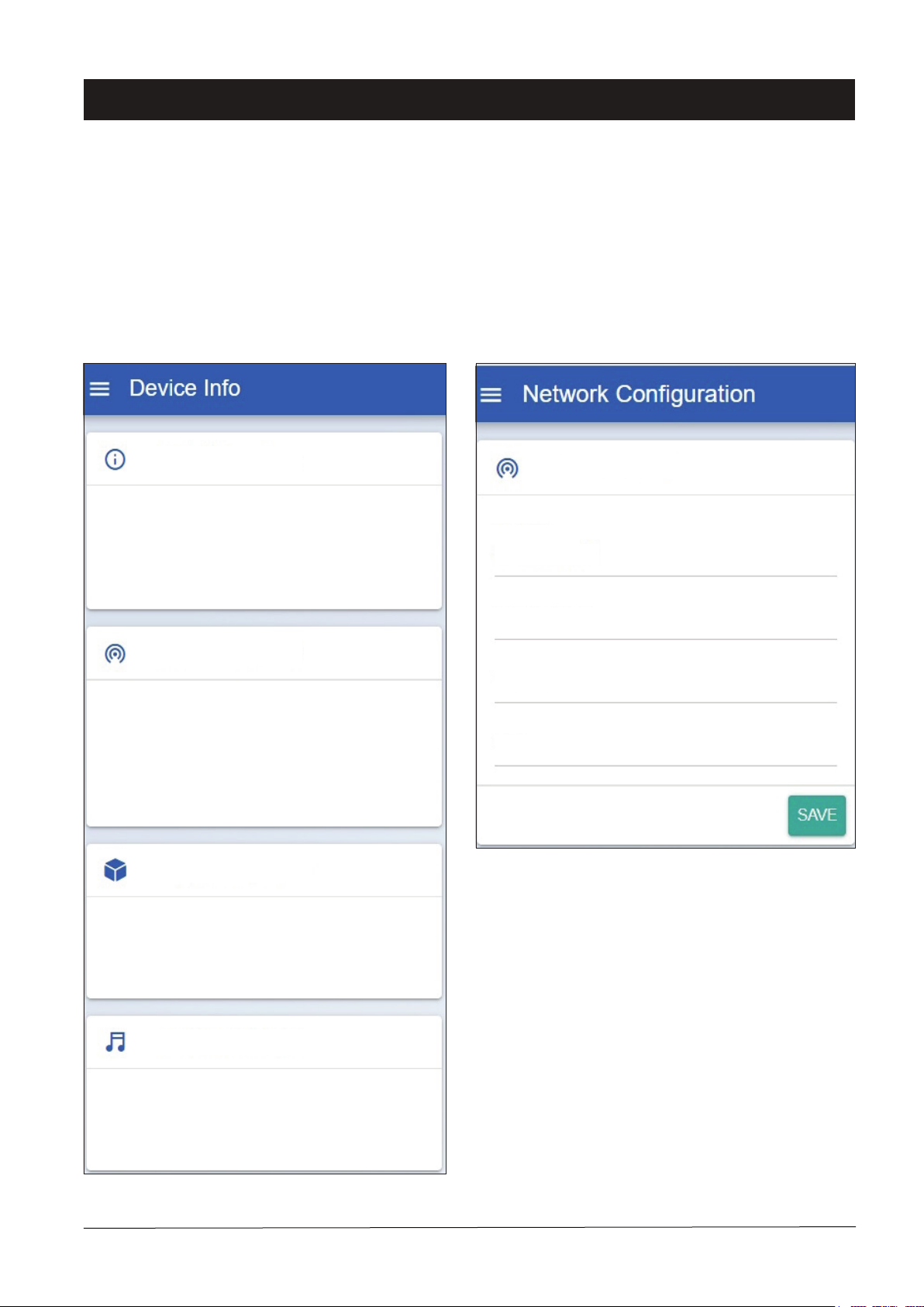
Amperes Electronics iPX5455 User manual

INSTRUCTION MANUAL
iPX5455
4 Ch Ethernet Paging / Music Client
( Audio Extractor )
Ver 1 / 2023
iPX5455 is a 4 channel Ethernet Paging / Music client in a 1 hu rack mounted casing. It is also known as audio extractor, which
extracts audio and data from network to analogue audio outputs and RS485 data. Each module works independently and
thereby each of them shall be assigned into individual unique IP address.
It is most suitable for rack mount installations, providing a neat rack setup as compared to small loose module, most notably
when multiple channels are to be used in the same rack.
amperes
iPX 5455
ETHERNET PAGING / BGM CLIENT
POWER
SERVER
STATUS
STREAMING
SIG
CH1 CH2 CH3 CH4
applicable for iPX5155 FW 2.31 and above

Parts Identification
2
PAGE 2 iPX5455 | 4 CH.ETHERNET BGM / PAGING CLIENT
3
6
7
1
9
5
48
POWER - This blue LED shall lit when each module is powered On.
SERVER - This green LED shall lit when each module successfully establish a connection with Paging Server (iPX5101).
STATUS - Blink whenever there is a network activity ongoing.
STREAMING - Blink whenever each module is transmitting / receiving streaming audio to / from another paging client or
music server
1. INDICATOR LEDS
24V DC power supply input which powers each individual module of iPX5455.
2. POWER PORT
Ethernet port for connecting to network switch. Each module shall have its own network port and to assign a unique IP
address when doing setup.
3. ETHERNET PORT
Button to allow iPX5155 enters Bootloader mode or reset settings to factory defaults. Each module shall have its individual
button.
4. RESET BUTTON
This port provides a dry contact which can be used to connect E/M overriding signal or activate ALL CALL at
speaker zone selector.
5. RELAY CONTACT
We can activate the iPX5155 module using voltage free dry contact. Connecting PM series paging mic / MR1301 message
recorder / TI6100 Telephone Interface dry contact to this port will activate the iPX5155 and have their analog audio signal
stream to the network. This port only work when the iPX5155 operates as Input mode. (Refer page 7)
6. REMOTE TRIGGER PORT
For data transmission (RS485) among iPX5155, PD paging mic and zone decoder like TD6240 / TD6400 / TD6080.
7. RS485 PORT
amperes
iPX 5455
ETHERNET PAGING / BGM CLIENT
POWER
SERVER
STATUS
STREAMING
SIG
CH1 CH2 CH3 CH4
-OUT
+OUT
+IN
GND
-IN
GND
OUTPUTINPUT
-B
+A
C
C
T
T
RS485TRIG
CONTACT
NO
AUDIO
RESET
ETHERNET
-
+
DC 24V
400mA
-OUT
+OUT
+IN
GND
-IN
GND
OUTPUTINPUT
-B
+A
C
C
T
T
RS485TRIG
CONTACT
NO
AUDIO
RESET
ETHERNET
-OUT
+OUT
+IN
GND
-IN
GND
OUTPUTINPUT
-B
+A
C
C
T
T
RS485TRIG
CONTACT
NO
AUDIO
RESET
ETHERNET
-OUT
+OUT
+IN
GND
-IN
GND
OUTPUTINPUT
-B
+A
C
C
T
T
RS485TRIG
CONTACT
NO
AUDIO
RESET
ETHERNET
CH2CH1 CH3 CH4
MADE IN MALAYSIA
amperes electronics
another quality product from
Model : iPX5455
ETHERNET PG / BGM CLIENT
amperes
R
DC input 24V Max. 400mA
The LED indicators for various status of individual channel, when lit, indicates the followings :
Bootloader mode: To enter this mode, hold the reset button until POWER, SERVER and STATUS LEDs lit. Enter this
mode to do firmware updating if normal mode updating does not work. All settings remain intact in this mode.
Reset to factory default settings: Hold the reset button until POWER, SERVER, STATUS and STREAMING LEDs lit
will reset all settings to factory defaults.

General Schematic Diagram
PAGE 3iPX5455 | 4 CH.ETHERNET BGM / PAGING CLIENT
Connect paging mic or other audio source analog audio signal to this port. The signal shall be in balanced line level.
8. AUDIO INPUT PORT
iPX5155 broadcast analog audio signal via this port to mixer or amplifier. The signal is in balanced line level.
9. AUDIO OUTPUT PORT
Note :
iPX5455 is basically a combination of 4 nos iPX5155 in a single enclosure. Thereby, we shall refer them as iPX5155 module in
the following sections.
ZONE 1
ZONE 2
ZONE 3
ZONE 4
POWER
PUBLICADDRESSPOWERAMPLIFIER
SIGNAL-40dB
SIGNAL-10dB
POWER
PROTECT
CLIP
480 Watts
amperes
PA2480
PA / QP / QD / DP
Power Amplifiers
Audio
POWER
PUBLICADDRESSPOWERAMPLIFIER
SIGNAL-40dB
SIGNAL-10dB
POWER
PROTECT
CLIP
480 Watts
amperes
PA2480
Audio
POWER
PUBLICADDRESSPOWERAMPLIFIER
SIGNAL-40dB
SIGNAL-10dB
POWER
PROTECT
CLIP
480 Watts
amperes
PA2480
amperes
10BaseT ( Unmanaged )
Amplifier Monitor Panel
Amperes AM4120
Cat5e
Desktop Paging Mic
Amperes iPD1280
Network Switch
Network Switch /
Fiber Converter
iPX5101 amperes
Network BGM Server
Amperes iPX5200 Audio Sources
Network Controller
Amperes iPX5101
FIRE amperes
AM6000
IPX5200 amperes
MR1301 amperes
Dry Contact Links From FAS
Fire Alarm Interface
Amperes FI6000
EVAC Message Player
Amperes MR1301
Network Emergency Mic
Amperes iEP1200
FI6000 amperes
POWER
PUBLICADDRESSPOWERAMPLIFIER
SIGNAL-40dB
SIGNAL-10dB
POWER
PROTECT
CLIP
480 Watts
amperes
PA2480
Paging / BGM Client
Amperes iPX5455
Audio
Audio
PC with Pre-Loaded
Amperes PMX Software
TO OTHER SUB
SYSTEM VIA
FIBER / LAN
The schematic above shows an application of iPX5455 with each individual output representing a single zone.
Combination of TD6400 / 6080 or TD6240 + ZS can be used for zone expansion.
iPX5155 modules can be used is sub rack alongside iPX5455.
Similar to iPX5155, each of the module can be assigned as input or output.

Connection Diagram
PAGE 4 iPX5455 | 4 CH.ETHERNET BGM / PAGING CLIENT
-OUT
+OUT
+IN
GND
-IN
GND
-B
+A
C
C
T
T
Audio output to amplifier
with balanced line
signal, +4 dBu
To network switch / LAN
port
24V DC input, max 400
mA rating
Volume Controllers
overriding or any
other applications.
Using iPX as Output
Each module within iPX5455
works independently, can be used
as Input or Output.
This diagram shows the module
used as output. RS485 can be
used to control zone decoder.
If each module is to represent a
single zone, RS485 connection to
TD can be omitted.
Also refer to Page 6 and 7 for
device setup.
To TD zone decoder
-OUT
+OUT
+IN
GND
-IN
GND
-B
+A
C
C
T
T
Using iPX as Input with PD Paging Mic
PD Series paging
microphone
RS485
Line Bal Audio
2 Pair Screen
PD Series of paging microphones such as PD1240,
1280 and 1160 can be connected to IPX environment via
iPX5455, setting the module as input source.
Streaming of any audio and data from paging micro-
phone is event triggered, that is only when the paging
mic is activated.
Also refer to Page 6 and 7 for device setup.
-OUT
+OUT
+IN
GND
-IN
GND
-B
+A
C
C
T
T
Using iPX as Input with Analog Mic or Telephone Interface
Any audio from paging mic or any other audio source
can be connected to iPX environment using one of the
module.
Streaming of any audio is event triggered, and destina-
tion of the audio can be programmed.
Also refer to Page 6, 7 and 8 for device setup.
Line Bal Audio
Contact Trigger
PM1000 Paging
Mic
Telephone Interface /
Message Player /
Alarm Source

Device Setup
iPX5455 shall require some setups via web browser. Kindly follow instruction listed below. The default IP address of each module
is 192.168.0.100. Default Username and Password are both “admin”.
Device Info
The first page appear upon login shall be Device Info.
Information such as firmware version, networking addresses
and paging server status are shown. No configuration is
needed in this page.
Firmware Version
Serial Number
Build Date
Device Name
2.29
0000000000000000000
02 Nov 2020
Paging / Music Client
MAC Address
IP Address
Subnet Mask
Gateway Address
Data Port
114:106:118:28:6:29
192.168.0.155
255.255.255.0
192.168.0.1
3000
Server Name
Server IP
Server Version
Blk A Paging Server
192.168.0.101
2.29
Server Name
Server IP
Server Version
Blk A Music Server
192.168.0.120
2.07
Device Information
Network Information
Paging Server Status
Music Server Status
Network Configuration
Edit iPX5155 IP address, Subnet address and Gateway
address here to suit you networking environment. It is recom-
mended to leave the Data port number unchanged. Click the
“SAVE” button to save your changes.
IP Address
Subnet Address
Gateway Address
Data Port
192.168.0.155
255.255.255.0
192.168.0.1
3000
IPv4 Configuration
PAGE 5iPX5455 | 4 CH.ETHERNET BGM / PAGING CLIENT

Device Setup
Paging Configuration
Paging Enabled: Enable this setting if an iPX5155 is used as a paging client. If the iPX5155 is merely used as a music
client, we can disable this setting.
Auto Connect: We can either turn On the Auto Connect to allow iPX5155 search and connect to Paging Server automati-
cally or turn Off the setting and specify the Paging Server IP address here.
Note: If Paging Server IP address is changed to an unknown value, turn On the Auto Connect allow auto capture the server
IP address and show up in the device information page.
Input Mode Settings
Output Mode Settings
Paging Enabled
Auto Connect
Operating Mode
Start Zone End Zone
Restricted Zones
Dry Contact
Any Paging
Input Output
1248
2,4,6 - 10
Paging Enabled
Auto Connect
Operating Mode
Paging Server IP Address
Input Output
192.168.0.101
Auto Override Low Priority
PAGE 6 iPX5455 | 4 CH.ETHERNET BGM / PAGING CLIENT
Also refer to Page 8 in relation to Remote Trigger
activation.

Device Setup
An iPX5155 can either operate in Input mode or Output mode. Depends on the chosen operating mode, some settings only
available in Input mode while some only in Output mode.
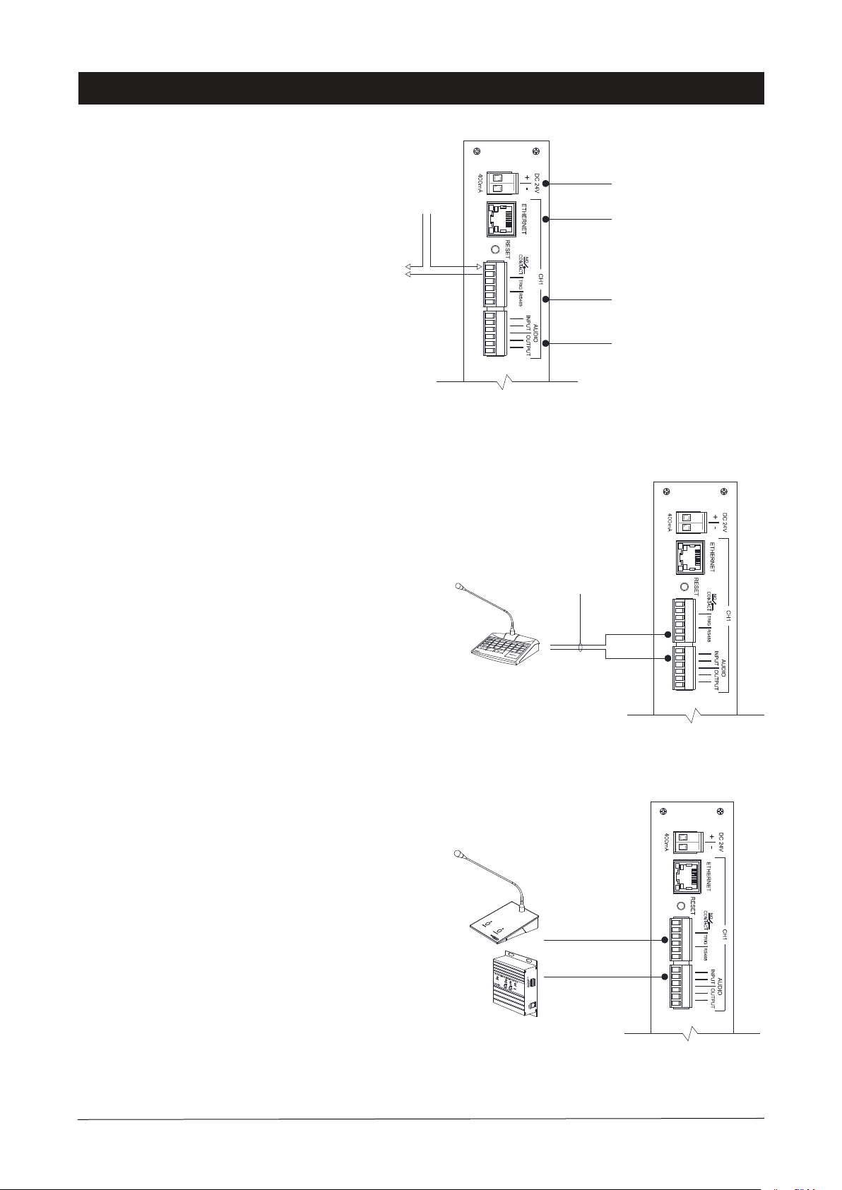
(A) Input Mode: An iPX5155 that a paging mic / TI6100 is physically connected to shall be operated in Input mode. This
allows the iPX5155 to receive paging audio, RS485 data or dry contact triggering from the devices.
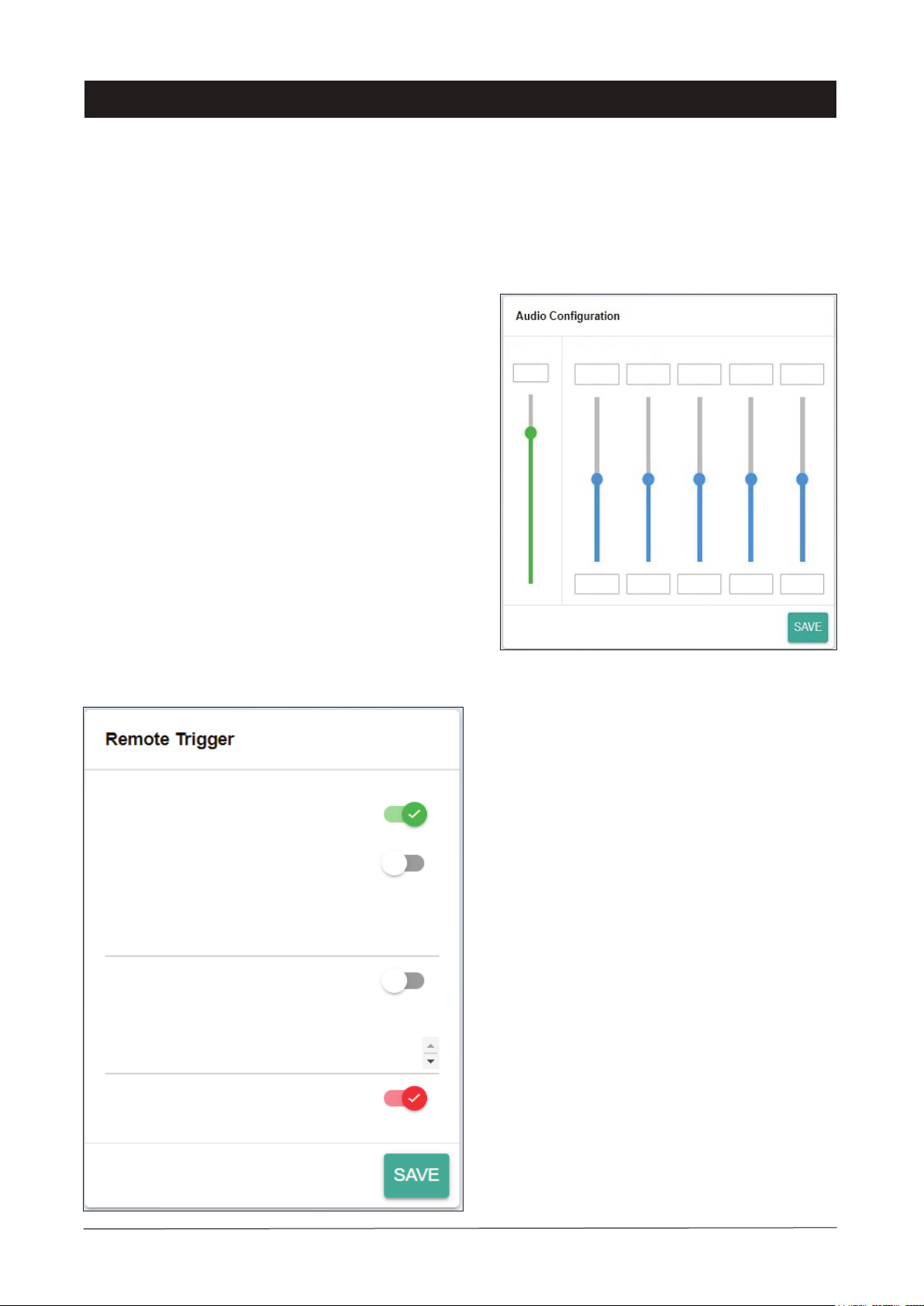
Auto Override Low Priority (AOLP): Enable this setting if we want to allow paging mic that connected to iPX5155
RS485 port to override other lower priority devices. For iPD / PD series paging mic the priority level shall be configured in the
paging mic configuration.
(B) Output Mode: An iPX5155 that an amplifier / zone decoder is connected to shall be operated in Output mode such that
this paging client able to send the paging audio to the amplifier to play the paging or send the RS485 data to activate zone decod-
er channels.
Below are settings that available in Output mode:
Start / End Zone: This is iPX5155 serving zone range. Whenever paging zones that fall within this zone range but excluded
in the Restricted Zones (see below) were called, the iPX5155 shall output the paging audio and activate the corresponding
channels on zone decoder.
Restricted Zones: Zone(s) that not served by iPX5155.
Dry Contact: There are three options to control the activation of iPX5155 Relay Contact port. Refer to Table.1
Dry Contact Setting Outcome
Disable
Any Paging
Siren, Emergency Paging or Messag-
ing
Disable Relay Contact
Activate Relay Contact when user
a) Activate paging on iPD / PD series paging mic
b) Activate paging on PM1000 / TI6100 by triggering the Remote Trigger port of an
iPX5155 that operate in Input mode
c) Activate siren, emergency paging or messaging on iEP1200 / iEP1202
d) Activate siren of iEP1200 / iEP1202 via iPD / PD series paging mic
Relay Contact only get activated when user perform item (c) and (d) above
Table.1: Activation of Relay Contact Port
Operating Mode
PAGE 7iPX5455 | 4 CH.ETHERNET BGM / PAGING CLIENT

Device Setup
Volume 5 Band Equalizer
80%
100
Hz
250
Hz
1K
Hz
4K
Hz
10K
Hz
0
dB
0
dB
0
dB
0
dB
0
dB
Remote Trigger
Remote Trigger settings only available when iPX5155 operates
in Input mode.
Enabled: Enable this setting when a PM1000 / TI6100 is
used as the paging source to activate iPX5155 via its Remote
Trigger port.
No Priority: There are 10 paging priority levels. Enable this
setting shall make a paging device that connected to this
iPX5155 operates in the lowest priority level. Disable this
setting shall allow us to configure level 1 to 10. The lower the
number the higher the priority level.
All Call: Enable this setting to page to all zones when the
iPX5155 Remote Trigger port get activated. Disable this setting
shall allow us to configure a zone range.
Auto Override Low Priority (AOLP): Enable this
setting shall allow a paging mic that connected to this iPX5155
Remote Trigger port to override other lower / same * priority
devices.
* To allow same priority override, user need to enable Same
Priority Override setting in iPX5101.
Audio Configuration
To adjust volume and EQ of paging audio. These
settings only available when iPX5155 operates in
Output mode.
Enabled
No Priority
All Call
Auto Override Low Priority
Zones
Priority
1
PAGE 8
iPX5455 | 4 CH.ETHERNET BGM / PAGING CLIENT

Device Setup
BGM Configuration
BGM configuration only applicable to iPX5155 that operate in
Output mode.
BGM Enabled: Enable this setting if an iPX5155 acts as
a music client. If an iPX5155 serves as both paging and
music client, enable this setting shall allow music to be
played when no paging is active and cease playing music
when paging is active.
Auto Connect: We can either turn On the Auto Connect
to allow iPX5155 search and connect to a Music Server
automatically or turn Off the setting and specify the Music
Server IP address here.
Note: If Server IP address is changed to an unknown value,
turn On the Auto Connect allow auto capture the server IP
address and show up in the device information page.
Audio Configuration: To adjust volume and EQ of
music audio.
Audio Configuration
BGM Server - IPX5200 / PMX
Volume 5 Band Equalizer
80% 0dB 0dB 0dB 0dB 0dB
100Hz 250Hz 1KHz 4KHz 10KHz
BGM Enabled
Auto Connect
Device Name
Paging / Music Client
Enter new username
Enter new password
Unit Configuration
Authentication System
Unit Configuration: We can enter a meaningful Device
Name here. E.g. “Paging / Music Client”. The name shall be
shown in iPX5155 Device Info page and iPX5101 Paging
Server - Client Browser tab.
Authentication: You can alter the user name and
password to avoid unnecessary access to the system.
PAGE 9iPX5455 | 4 CH.ETHERNET BGM / PAGING CLIENT

Update Firmware
Update Firmware: System firmware shall be updated once in a while when new features are available or to fix bugs. As
each module is basically an iPX5155, they will use iPX5155 firmware and each module is to be updated individually. There
are 2 methods of doing;
Update firmware in Normal Operation Mode
iPX5155.acfr
1.16
12-10-2020
File Name
Firmware Version
Build Date
1. Open a browser and type in the iPX5155 IP Address.
2. Under “System” page look for “Update Firmware” section as shown in below.
1. Press & hold the reset button until “ STREAMING ” LED is turned ON. This will set the IP address to default address
192.168.0.100.
2. Open a browser and enter the IP address 192.168.0.100. A web page as shown below shall appear.
3. Select “ Upload Firmware ”, choose a binary file with “ .acfr ” extension and click “UPLOAD”
4. Once the uploading is completed, the browser shall enter the login page.
Update firmware in Bootloader Mode
If the iPX5155 “hanged”, it is required to perform system reset by :
Click the Upload
Firmware button to find
the updated firmware
file.
Find the updated firmware file.
Ready to upload, click Upload
button to upload the firmware.
Updating progress
After finish updating firmware, the browser automatically
restart.
IPX5155.acfr
IPX5155.acfr ACFR File
IPX5155
02.29
394 KB
IPX5155
394 KB
Click “ SELECT FIRMWARE” and choose a binary file with “.acfr” extension. Click
“UPLOAD”.
Once the update is completed, the browser should enter the login page.
PAGE 10 iPX5455 | 4 CH.ETHERNET BGM / PAGING CLIENT

PAGE 11
Technical Specification
Power requirement :
Voltage
Current
Power consumption
Connection
- No of Channel
- LAN interface
- Protocol
Audio
- Analog in (max)
- Analog out
- Input impedance
- Input capacitance
- Total harmonic distortion (THD)
- S/N ratio (full scale signal)
- Paging encoding
User interface
Firmware upgrade
Operating condition :
Temperature
Humidity
Case :
Dimension (WxHxD)
Weight
18 ~ 24V DC (Normally DC 24V)
240 mA ( All modules operating )
6 W ( All modules operating )
4 ( operates individually )
RJ45 (10 / 100 Base - T)
TCP/IP, UDP, HTTP, IGMP, ADMP
1.25 Vrms
1.25 Vrms (with Analog in 1.25 Vrms)
300 Ohm
100 pF
0.1%
83 dB
G.722
Google Chrome, MS Edge, IE V8+
Via Web Browser
-20°C ~ 80°C
0 - 70%
482 x 44 x 180 mm
2.4 kg
Note:
The above specifications are correct at time of printing but subjected to changes without prior notice due to product
improvements.
iPX5455 | 4 CH.ETHERNET BGM / PAGING CLIENT

Warranty Conditions
Disclaimer
AMPERES ELECTRONICS SDN BHD
MADE IN MALAYSIA
Published : MAY 2023
ISO 9001: 2015
Design & Manufacture of Public Address Equipment and Systems
Only Amperes Electronics Service Centres are allowed to make warranty repairs : a list of Amperes Electronics authorized
service centres may be asked by the purchaser or send directly to Amperes Electronics Sdn Bhd at 70 Jalan Industri PBP3,
Tmn Perindustrian Pusat Bandar Puchong, 47100, Puchong, Selangor. This warranty is not valid if repairs are performed by
unauthorized personnel or service centres.
This warranty covers only repairs and replacement of defective parts. Cost and risk of transportation as well as removal and
installation of the product from the main system are for the account of the purchaser. This warranty shall not extend to the
replacement of the unit.
This warranty does not cover damages caused by misuse, negligence in application as well as using the product with power
supply voltage other than shown on the product, or any other power supply source / adapter not recommended by the
manufacturer.
This warranty does not cover damages caused by fire, earthquakes, floods, lightning and every cause not directly related to
the unit.
This warranty does not include any indemnity in favor of the purchaser or the dealer for the period out of use of the unit,
moreover the warranty does not cover any damages which may cause to the people and things during the use of the product.
This warranty certificate is valid only for the described product, and is not valid if modifications are made on this certificate or
identification labels applied to the unit or any other modifications to the physical unit other than its intended usage.
This warranty covers all the material and manufacturing defects and is valid for a period of 36 months from the date of
purchase or for a specified period in countries where this is stated by a national law. In this case, the extension is valid only in
the country where the product is purchased.
Amperes Electronics Sdn Bhd is not obliged to modify previously manufactured products under warranty if the design changes
or improvements are made.
The purchaser is deemed to agree to the above warranty conditions once the product packaging is unpacked., Otherwise the
product shall be returned to the seller in proper original condition.
Information contained in this manual is subjected to change without prior notice and does not represent a commitment on the
part of the vendor. Amperes Electronics Sdn Bhd shall not be liable for any loss or damages whatsoever arising from the use
of information or any error contained in this manual.
It is recommended that all services and repairs of this product to be carried out by Amperes Electronics or its authorized
service agents.
Amperes products must only be used for the purpose they were intended by the manufacturer and in conjunction with this
operation manual.
Amperes Electronics Sdn Bhd cannot accept any liability whatsoever for any loss or damages caused by service, maintenance
or repair by unauthorized personnel, or by use other than that intended by the manufacturer.
Table of contents
Popular Scrubber manuals by other brands

Nederman
Nederman MagnaTrack HS Original user manual

Record Power
Record Power DX1000 Original instruction manual

Weller
Weller Zero Smog TL Translation of the original instructions

Nilfisk-Advance
Nilfisk-Advance Nilfisk Smart user manual

pro bel
pro bel 4429 Technical manual

Kärcher
Kärcher BD 90 R Classic Bp Original operating instructions